Mechanical Design of Self-Reconfiguring 4D-Printed OrigamiSats: A New Concept for Solar Sailing
 Aloisia Russo1,2†
  Bonar Robb3†
  Stefania Soldini1*
  Paolo Paoletti1
  Gilles Bailet3
  Colin R. McInnes3 Juan Reveles2
  Ahmed K. Sugihara4 Stephane Bonardi4
  Osamu Mori4
- 1University of Liverpool, Department of Mechanical, Materials and Aerospace Engineering, Liverpool, United Kingdom
- 2Oxford Space Systems, Oxford, United Kingdom
- 3Space and Exploration Technology Group, James Watt School of Engineering, University of Glasgow, Glasgow, United Kingdom
- 4Institute of Space and Astronautical Science, JAXA, Sagamihara, Japan
In this article, a self-reconfiguring OrigamiSat concept is presented. The reconfiguration of the proposed OrigamiSat is triggered by combining the effect of 4D material (i.e. origami’s edges) and changes in the local surface optical properties (i.e., origami’s facets) to harness the solar radiation pressure acceleration. The proposed OrigamiSat uses the principle of solar sailing to enhance the effect of the Sun radiation to generate momentum on the Aluminised Kapton (Al-Kapton) origami surface by transitioning from mirror-like to diffusely reflecting optical properties of each individual facet. Numerical simulations have demonstrated that local changes in the optical properties can trigger reconfiguration. A minimum of 1-m edge size facet is required for a thick-origami to generate enough forces from the Sun radiation. The thick-origami pattern is 3D-printed directly on a thin Al-Kapton film (the solar sail substrate which is highly reflective). An elastic filament (thermoplastic polyurethane TPU) showed best performance when printing directly on the Al-Kapton and the Acrylonitrile Butadiene Styrene with carbon fiber reinforcement (ABS/cc) is added to augment the origami mechanical properties. The 4D material (shape memory polymer) is integrated only at specific edges to achieve self-deployment by applying heat. Two different folding mechanisms were studied: 1) the cartilage-like, where the hinge is made combining the TPU and the 4D material which make the mounts or valleys fully stretchable, and 2) the mechanical hinge, where simple hinges are made solely of ABS/cc. Numerical simulations have demonstrated that the cartilage-like hinge is the most suitable design for light-weight reconfigurable OrigamiSat when using the solar radiation pressure acceleration. We have used build-in electric board to heat up the 4D material and trigger the folding. We envisage embedding the heat wire within the 4D hinge in the future.
1 Introduction
Conventional spacecraft designs generally comprise of a central spacecraft bus that mounts multiple deployable structures (e.g., antennas and solar arrays). Deployables are used to minimise the packed volume in the launch vehicle and to provide on-orbit configurations which aim to extend the surface area of the spacecraft. These devices are generally large structures deployed in-space utilising origami-based designs (Larson and Wertz, 1992). The benefits of origami-based designs for these deployable structures include a reduction in stowed volume, and an ability to deploy the structure with minimal actuation and few moving parts (Peraza Hernandez et al., 2019). Morgan et al. (2016) give an overview of the advantages of origami designs specifically for aerospace applications, and demonstrates the wide range of potential uses, including: protective bellows for Martian rovers, expandable habitats for the ISS, and deployable antennas. The most well-known example of origami used in spaceflight engineering is the Miura fold (Nishiyama, 2012), which allows a structure composed by rigid panels to be folded compactly and then unfolded in one motion, and has been used for deployable solar panel arrays. A design procedure for reversible rigid origami solar panels has been proposed and demonstrated through the realization of a 3D printed prototype of mechanical hinges (Russo, 2020).
Spacecraft deployables tend to be lightweight to reduce launch costs. These large appendages can cause the spacecraft to experience disturbance torques due to the Solar Radiation Pressure (SRP) acceleration, which must then be counteracted by the attitude control system. Conversely, solar sails are highly reflective deployable structures (i.e., “space mirrors”) specifically designed to enhance the effect of the Sun’s radiation as a primary form of fuel-free propulsion with the advantage of a longer mission lifetime. Solar sails are large [e.g., 200 m2 (Ono et al., 2013)] and two-dimensional lightweight membrane structures [e.g., 7.5 μm thickness (Ono et al., 2013)] folded using origami based design to fit within the launcher’s volume. Natori et al. (2015) discusses the use of origami-based design for deployable membrane spacecraft, giving a number of examples of deployable fold patterns for this application.
Most of these structures (deployable devices and solar sails) are currently designed to maintain a fixed-shape once deployed, and a single spacecraft usually mounts multiple deployables for different purposes. We propose a spacecraft design which integrates solar sailing capabilities with functionality which would traditionally require deployable structures, through the use of a reconfigurable origami satellite or “OrigamiSat”. Such a shape-changing spacecraft could open a new paradigm in spacecraft design, where a “flat” OrigamiSat could be folded into several shape configurations, each performing different functions. In this new paradigm, solar sailing could be one of the operational modes of a multi-functional OrigamiSat, moving away from the conventional view of SRP as a disturbing force for deployables. When flat, an OrigamiSat could operate as a solar sail, providing fuel-free propulsion or attitude control. The OrigamiSat could then be reconfigured and operate, for example, as a parabolic reflector (Borggrafe et al., 2015), thereafter switching between operational modes as required. Furthermore, it is possible that the shape reconfiguration itself could be at least partially controlled through the use of SRP and surface reflectivity modulation (SRM), in a fashion similar to the use of Reflectivity Control Devices (RCDs) for the attitude control of solar sails. This could be achieved by mounting RCDs on different facets of the origami design. By modulating the reflectivity of each facet, the force due to SRP could be controlled and shape-reconfiguration achieved by subjecting the OrigamiSat to the forces required to perform the desired “folds” of its underlying origami pattern.
The active shape control of solar sails has previously been considered for some specific applications, though the degree of shape reconfiguration required by a multi-functional OrigamiSat would be more extensive than any of the following proposed concepts. Reconfiguring the shape of a solar sail modifies the area-to-mass ratio of the spacecraft, allowing orbit control and enabling new missions. For example, Soldini et al. (2019) show that instantaneous changes of the area-to-mass ratio of a spacecraft can be used to perform fuel-free transfers between Lissajous orbits in the Sun-Earth system, suggesting this could be achieved through the use of foldable “flaps” being deployed or stowed as required. Farrés et al. (2019) have explored solar sails transfer for L4 and L5 lagrangian points while Soldini et al. (2016) have investigated the use of shape-changing solar sails for end-of-life disposal of large spacecraft in the L2 Lagrangian point. Ceriotti et al. (2014) introduce a quasi-rhombic pyramidal solar sail design in which the sail geometry is actively controlled via extendable booms, enabling orbit control. Takao, (2020) investigates the active-shape control of spinning solar sails, demonstrating effective shape control can be achieved using either tethers or RCD devices. Borggrafe et al. (2015) demonstrate that a parabolic shape can be produced in a slack reflective membrane by varying the surface reflectivity across the membrane surface. This concept is similar to suggestion that the shape-reconfiguration of an OrigamiSat could be triggered by SRP and differences in local surface reflectivity, though the mechanics of an origami pattern folding are quite different to the membrane dynamics considered in this example.
The local surface reflectivity of the proposed OrigamiSat could be controlled via RCDs. RCDs are proven technology for solar sails, as demonstrated by the IKAROS mission which used such devices to generate attitude control torques (Ono et al., 2013). For tuning the torque acting on the sail Ma et al. (2016) describes the use of an RCD based on a polymer dispersed liquid crystal (PDLC), which enables propellant-less attitude control through reflectivity modulation via an applied voltage. In Lai et al. (2019), a 3D-printed corner cube retro-reflector was manufactured which is tunable through the PDLC, cutting costs related to the manufacturing process. Such devices would be an efficient means of achieving shape control for an OrigamiSat, as they do not require propellant, have low mass, and could be integrated into the reflective membrane of an OrigamiSat’s facets during manufacture through the use of contemporary additive manufacturing techniques.
In this work we use multibody dynamics simulations to model the in-space folding behaviour of an OrigamiSat with variable local reflectivity. As origami-based design is so frequently found in the area of spaceflight engineering, there is a need to accurately model the behaviour of these origami structures in orbit. McPherson and Kauffman, (2019) give a review of research on the dynamics and estimation of origami space structures, highlighting the importance of accurate dynamic models, particularly during the deployment phase. Examples given by McPherson and Kauffman, (2019) include the work of Miyazaki and Iwai, (2004), where a spring mass model is used to model the membrane dynamics of a six panel solar sail. Zhang and Zhou, (2017) present a simplified model of a spinning solar sail during deployment, and perform an ABAQUS simulation of the origami fold pattern deploying. Although there is some literature on modelling the deployment dynamics of solar sails, the deployment of these sails is most often enacted by centrifugal means as the central hub spins and the sail unfolds (Takao, 2020), and the sail itself is considered to be a flexible membrane. The OrigamiSat proposed in our work consists of reconfigurable rigid panels (the OrigamiSat facets), acted upon by SRP acceleration, therefore the mathematical modelling presented in this article is quite different to the cases found in literature.
Manufacturing is an important consideration for future OrigamiSat development. The manufacturing process of traditional solar sails is complex, requiring the manual folding of the thin sail membrane (Stohlman et al., 2020). In the second part of this paper, we consider the manufacturing of an OrigamiSat, and in particular how additive manufacturing (AM) would be particularly suitable for this application. The design and manufacturing flexibility offered by AM techniques, together with its capability of combining multiple materials (structural, photo-voltaic, conductive etc) in a single pass (Okaro et al., 2019), will enable new and more effective solar sail designs such as the OrigamiSat. We use additive manufacturing to explore the design of an OrigamiSat folding mechanism and for the rapid prototyping of a self-reconfiguring solar sail. The use of AM and rapid prototyping has also allowed us to investigate a variety of candidate materials for the OrigamiSat folding mechanism and membrane, with results discussed in the latter part of this paper.
We also consider the use of Shape Memory Polymers (SMPs) filament (commercially know as 4D material) as an additional actuator for OrigamiSat folding, and have incorporated these materials in our prototyping. Here, we propose incorporating SMP material in the hinge mechanism of the OrigamiSat, such that when heat is applied to the SMP, folding around the hinge is effected. Such materials have recently been of great interest in the spaceflight community due to their novel properties and wide-ranging applications. Wu et al. (2018) proposes a self-folding polymer membrane based on space-qualified materials and is potentially mass-producible by industrial roll-to-roll processes. Different studies have been made which harness the properties of “smart materials” such as Shape Memory Alloys (SMAs) or SMPs. One example is the work of Karmakar and Mishra, (2021), where an SMA-based linear actuator has been used for controlling the deployment of a Light Sail. Bovesecchi et al. (2019) explore the self-deployment of a solar sail through the construction of three different prototypes, demonstrating the utility of SMAs for such applications. SMAs have also been used by Inglesias, (2020) for the development of a self-folding hinge architecture for origami-inspired thin architecture, which is suitable for space applications. An example of an external force being used to effect the self-folding and spontaneous buckling of a thin sheet of SMP is presented in Zhang et al. (2017), and is particularly relevant to our work in that this external force could represent SRP in the case of an OrigamiSat.
This paper is organised as follows. In Section 2, a brief summary of the long-term vision is given, describing the aims and scope of the work. Section 3 contains mathematical modelling and the results of numerical simulation, used to investigate the feasibility of SRP triggered reconfiguration of OrigamiSats, while Section 4 focuses on OrigamiSat manufacturing, in which we investigate the use of AM techniques for rapid-prototyping purpose.
2 OrigamiSat Mission Application
In this article, a new paradigm towards space mission design has been proposed where a swarm of shape-changing OrigamiSats are employed for achieving multi-operational mission goals. A new concept of origami solar sail’s membranes is here explored which makes use of 3D printable materials on a high reflectivity material (a thin Al-Kapton film). The optical properties of the facets is assumed to be controlled by Reflective Control Devices (RCDs) while the edges are assumed to be actuated by embedded heaters, which will activate the shape memory polymer (4D material). Thus, our design evaluates the use of hybrid thermo-optical properties to enable reconfigurability of an OrigamiSat. Figure 1 shows an illustration of a simple OrigamiSat made of triangular facets (black rectangle). The central facet is assumed to have body mounted solar cells on the front and hardware on the back. The other facets are connected to the central one through 4D-printed edges. The optical properties of the other facets are assumed to be controlled by RCDs. The system is considered to be fully integrated and the edges are directly printed on the Kapton membrane. When the RCD is “ON” the facet is specular reflective (i.e., dark orange in Figure 1) while when “OFF” the facet’s optical property changes to diffuse reflection (i.e., light yellow in Figure 1). Local changes in the optical properties of the facet triggers reconfiguration due to the different modulation in the solar radiation pressure acceleration. Figure 1 shows our vision for the use of shape-changing OrigamiSats. A swarm of OrigamiSats is initially stowed in the launcher 1), each single OrigamiSat is deployed and the actuation can be achieved by actuating the 4D edges. Once the swarm of OrigamiSats is fully deployed, the next step is to assembly On-orbit to form a large Solar Sail 3). This allows for fuel-free transfer of a swarm of OrigamiSats at its final destination 4). Finally, the OrgamiSats can individually reshape by harnessing SRP and change the local reflectity of each facet as shown in Figure 1 for a lander 5). In this section, an overview of OrigamiSats idea and possible application is proposed. However, in this article we focus on the thermo-optical properties of a single OrigamiSat and its manufacturing process. Section 2 investigates the effectiveness of harnessing SRP through local optical changes of the facet via multi-body dynamics numerical simulations while Section 3 is devoted to the manufacturing process and the prototyping of the 4D-printed OrigamiSat. The simple design shown here is one of the OrigamiSat shape investigated in both Sections 2, 3 and used for comparison. Several origami folding sequences and manufacturing processes of the edges have been investigated in Sections 2, 3 respectively.
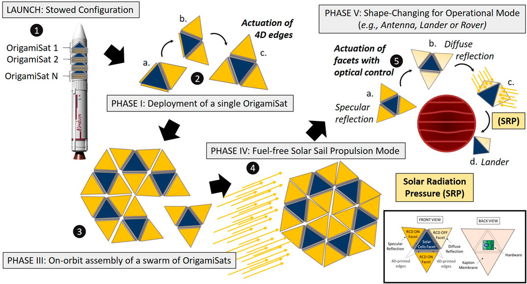
FIGURE 1. Illustration of a swarm OrigamiSat mission scenario (1), Launch configuration (2) Deployment of a single OrigamiSat by using 4D-printed edges (3) On-orbit assembly of a swarm of OrigamiSats (4) Fuel-free propulsion during the transfer phase and (5) Changes in the facet optical properties to trigger shape-changing.
3 Multibody Origami Folding Dynamics
In this section mathematical models of an OrigamiSat are developed and used to demonstrate that folding can be triggered by changing the local optical properties. First, a simplified, planar model of a single facet folding is used to derive some approximate scaling laws, and then a 2D model of linked facets is used to demonstrate the principle of SRP triggered shape reconfiguration. Finally a 3D multibody dynamics formulation is used to derive the equations of motion for arbitrary OrigamiSat fold patterns. These simulations have demonstrated that the momentum imparted to the facets by SRP is sufficient to trigger the self-folding of an origami solar sail. Simulations are then used to investigate the use of SRP and local SRM, whereby the surface reflectivity of individual facets of the OrigamiSat can be controlled, to perform active shape-reconfiguration of the sail. The effect of SRP is proportional to the area-to-mass ratio of each facet. Thus, it was possible to determine the minimum size required for each facet to generate enough “folding” momentum.
3.1 Folding Time of a Rigid Reflective OrigamiSat Facet
Here, the feasibility of using SRP to actuate the folding of high area-to-mass ratio, rigid facets is demonstrated using a simplified planar model of a rigid panel with a fixed edge constraint. This rigid panel represents a single facet of an OrigamiSat. The bending resistance from the hinge material of an OrigamiSat is estimated by assuming that the panel can be treated as a centre-loaded cantilever beam (Malka et al., 2014), and scaling laws for the hinge resistance torque and SRP force are developed.
Figure 2A illustrates a rigid, reflective, square facet with a fixed support at one edge and exposed to incoming radiation. The facet has sidelength l, and the unit vectors n an t define the surface normal and transverse vectors respectively. The transverse direction is defined to be the vector perpendicular to n and lying within the plane spanned by n and ui, which is the direction of the incident radiation. Considering only specular reflection and absorption of the incident radiation, for a Lambertian surface located at 1 astronomical unit (AU) from the Sun, the force acting on the facet is given by:
where ρ, the reflectivity, is the fraction of the incident radiation that is reflected, p = 4.563 × 10⁻⁶ N m−2 is the SRP constant one AU from the Sun, and A = l2 is the facet area (McInnes, 1999).
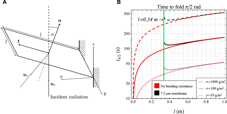
FIGURE 2. Reflective origami facet with fixed edge constraint (A) and change in facet folding time with length-scale, considering the bending stiffness of a 7.5 μm thick flexure hinge (B).
The surface is further assumed to be perfectly reflective, in which case ρ = 1 and Eq. 1 reduces to FSRP = 2 PA cos2αn. We now derive an expression for the time required for the facet to complete a fold through π/2 radians. If the facet has no bending resistance, and so is free to rotate around the fixed edge, the angular acceleration of the facet around the y-axis is given by:
where τ = Pl3 cos2α is the magnitude of the torque produced by the SRP force (FSRP), acting through the centre of the facet, and
The time taken for the facet to complete a rotation of π/2 rad is found by integrating Eq. 3 between α = 0 and π/2, which gives:
Eq. 4 is illustrated in Figure 2B, for areal mass densities ranging from 10 g/m2 (dotted red line in Figure 2B), that of near term solar sails, to two orders of magnitude higher (dashed red line in Figure 2B). (The black curves in Figure 2 represent the folding time when hinge resistance is taken into account, expressions for which are derived in the following section). A range of areal mass densities are considered to take into account the fact that the areal mass density of a swarm of OrigamiSats will likely be greater than that of a single (conventional) solar sail of equivalent total area. This is thought likely for two reasons, the first being that our analysis assumes a rigid facet, and the structural mass required to guarantee sufficient rigidity may increase the areal mass density. The second reason is that each OrigamiSat will require its own subsystems (communications, power etc), which will also contribute to an increase in mass (compared to a single, larger solar sail with a single set bus). While near term solar sails are expected to have an areal mass-density on the order of 10 g/m2, a more probable estimate for an OrigamiSat swarm is thought to be on the order of 100 g/m2. This estimate is made by considering the typical areal mass density of Cubesat solar sail designs (MacDonald and McInnes, 2011), and by supposing that a single OrigamiSat is likely to resemble a Cubesat in terms of the sail length scale and mass of the central spacecraft bus. As shown in Figure 2B, for areal mass densities of this order of magnitude the time required to fold the facet remains on minute time-scales for length-scales up to 100 m. This suggests that rapid, active shape re-configuration of OrigamiSats could be feasible using SRP.
3.1.1 Bending Resistance
In the previous section, we adopted a formulation where the rigid facet was free to rotate around the fixed edge in Figure 2A. We now introduce a more realistic model where the resistance to the facet’s rotation due to the hinge material is taken into account. The hinge is only required to constrain the OrigamiSat edges together, allowing relative rotation, and so one solution would be to use the sail material itself as a flexure hinge. The hinge stress due to the inertial forces of the rotating facets would need to be considered in the sail design process, but at this stage it is assumed that the hinge can be thin enough that a flexure hinge of sail material would be the solution offering the lowest bending resistance. In other words, it is assumed that the resistance of the hinge can be modelled as a linear torsion spring, where the resistance to rotation comes from the bending stiffness of the hinge material, rather than the resistance coming from the friction in a hinge or bearing.
The rotational bending stiffness is defined (Malka et al., 2014) by:
where E is the Young’s modulus, IyA the second moment of area of the hinge cross-section, and w, d, and l the width, thickness and length of the hinge respectively. Details of the hinge geometry and labelling convention can be found in Malka et al. (2014). It is assumed that the hinge material is thin enough that the curvature can be ignored, i.e., that the deflection discontinuously increases from 0 to ϕ at the hinge root, where ϕ is the hinge angle. This assumption was also made by Okuizumi and Yamamoto, (2009) when modelling creases in a 7.5 μm solar sail film and found to be accurate through non-linear finite element analysis, and through comparison with experiment. With this assumption, the bending resistance of the square facet illustrated in Figure 2A is given by:
which is found by taking Eq. 5 and setting w = L = l. The bending resistance does not depend on l because although the length of the fold root, and thus second moment of area increases proportional to l, the lever arm of the applied force also increases at the same rate. We now derive an expression for the time taken for a square facet subjected to SRP and with bending resistance to fold π/2 radians. With bending resistance, Eq. 2 becomes:
Again approximating
and the time taken to reach a fold angle of π/2 rad is now given by:
Equation 9 only has a solution if:
If the inequality in Eq. 10 is not satisfied, physically this means that the facet does not complete a rotation of π/2 radians, as the bending stiffness is too large compared to the SRP torque. If l is equal to the right hand side of the inequality then the facet just reaches π/2 radians, but will oscillate between α = 0 and π/2. For larger l, the facet will exceed this angle. Eq. 10 then gives the minimum facet length scale required to fold a facet using SRP for a given flexure hinge thickness. Using parameters of the IKAROS base membrane as a example (Okuizumi and Yamamoto, 2009), d = 7.5 μm and E = 3.2 GPa, Eq. 9 is shown in Figure 2B, along with the zero bending resistance case. For l < 0.34 m, there is no solution, while for l > 0.34 m the curve rapidly approaches the no bending resistance case, and the hinge resistance can effectively be ignored.
This analysis shows that, for a simplified, rigid facet model, it should be possible to rapidly fold an OrigamiSat using SRP. When the effect of the hinge bending resistance was considered, assuming the hinge is a thin flexure hinge of comparable thickness to the sail membrane itself, there is a minimum length scale required for the facet to be able to overcome the bending resistance and fold, but for length scales greater than this the bending resistance can essentially be ignored.
3.2 Planar Model of Linked, Reflective Facets
Having considered a simplified, single facet model in the previous analysis, we now extend our analysis to investigate the multibody dynamics of an OrigamiSat with multiple facets. To this end, a planar model of linked rigid bars has been developed, and is presented in this section. The aim of this work is to first verify results relating to folding-times obtained via the simplified single facet model of the previous section, and to assess the feasibility of using SRP to trigger the OrigamiSat folding when there are multiple rigid facets rotating relative to one another, and when the entire system is in free-space with no fixed supports.
3.2.1 Model Description
Here, the equations of motion for a multibody system consisting of N linked, rigid bars are presented. The generalised coordinates of the system are the x and y coordinates of each bar’s centre-of-mass, and the angle θ each bar makes to the x-axis. These coordinates are contained in the state vector q = [x1, y1, θ1, …, xN, yN, θN]. The system dynamics are found using the Lagrangian multipliers formulation, as described by, for example, Baraff, (1996). The constraints are satisfied by first solving:
for the vector of Lagrange multipliers λ, and then finding the constraint forces with:
where J is the Jacobian, defined by J = ∂C/∂q for the constraint equation vector C. Qa is the vector of applied forces. M is the mass matrix, which is diagonal with elements [m1, m1, I1, …mN, mN, IN], where mi,
The equations of motion are then given by:
which may be numerically integrated to evaluate the time-evolution of the system. The applied force vector Qa is the force due to SRP on each bar, and is found by evaluating Eq. 1 for each bar, for a given radiation incidence direction and the reflectivity ρi of each facet, and again assuming square facets such that
3.2.2 Results of Simulation
The planar multibody model is now used to investigate the dynamics of linked rigid, reflective facets in free space, subject to SRP. Simulations are performed using code developed by the authors in MATLAB, in which the equations of motion are implemented and numerically integrated. Numerical integration is performed with a Runge-Kutta 4th order integration scheme, and a simulation timestep of 1 s. The bar elements are given a length of 1 m, and the mass is calculated assuming an areal mass density of 10 g/m2. The incident radiation is directed along the positive y-axis. In the first simulation, two linked bars with perfect reflectivity ρ = 1 are considered. If initially, θ1 = θ2 = 0 rad, there is no relative rotation of the bars, as the SRP force is normal to both surfaces and thus in the same direction, so is experienced by the system as rigid body motion. A small initial relative angle is introduced, by setting θ1 = −0.01 rad and θ2 = 0.01 rad. This means that the SRP acts to fold the facets together as there is a small difference in the direction of the force on each facet. Through simulation, it was found that the two facets fold together in a time of 412 s. This is greater than the time suggested by Figure 2B for facets of this size. This is because there is no fixed support at the edge and each facet is free to accelerate in the y-direction when the force is applied. However, once the rotation begins it rapidly accelerates, as a greater portion of the SRP torque acts in opposing directions on the two facets, and the majority of the fold is completed within approximately 50 s which is more in line with the expected folding times given in Figure 2B.
By controlling the surface reflectivity of each facet, through the use of RCDs for example, folding can be induced without the need for an initial relative angular displacement, as was required in the previous simulation. This is because, as a consequence of Eq. 1, a facet of equal area with higher reflectivity will experience a greater force, and thus accelerate relative to a less reflective facet, resulting in a rotation around the joint between them.
A simulation was performed of a three facet system, with reflectivities given by [1, 0, 1] for facets one to three respectively, and all initial angles zero. These reflectivities represent an idealised case, though in practice the difference in reflectivity that could be achieved with RCDs will most likely be much smaller. Due to the difference in surface reflectivity between the facets, a fold is induced. Three facets are used here such that the symmetry prevents the overall system rotating, and so only the outer facets fold in while the centre facet remains flat. The facets are found to complete a fold of π/2 radians in 100 s. This is twice the value expected in from the fixed edge analysis in Figure 2B for l = 1 m, because unlike the fixed edge case the centre facet here is also accelerating in the positive y-direction. Since the force on the perfectly absorbing centre facet is exactly half that on the outer facets (initially), in the centre-of-mass frame the angular acceleration is half that which would be found for the fixed edge case. The system is shown in Figure 3A at t = 40 s, showing the outer facets have begun to fold inwards, away from the incident radiation. In Figure 3, grey facets are perfectly reflective while black facets are perfectly absorbing.
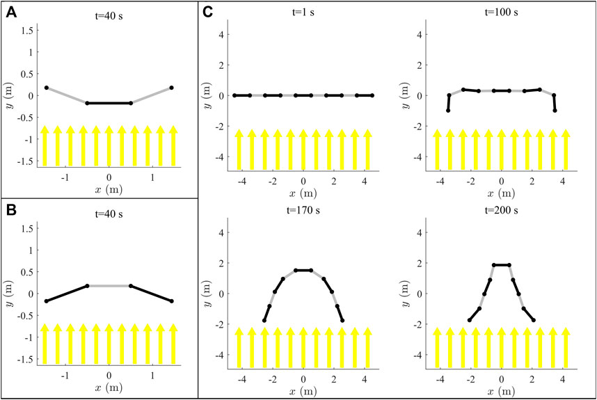
FIGURE 3. Results of simulations of 3 bar planar multibody system with opposing reflectivity patterns (A,B), and a nine bar system (C). Black represents a perfectly absorbing facet, while gray is perfectly reflecting.
By inverting the surface reflectivity, the fold direction can be reversed, as shown in Figure 3B. The facets again fold inwards in the exact same time as the previous case but this time in the opposite direction. Note that in the previous simulations, the facets are free to pass through each other, and do not shadow other facets from the incoming radiation. This causes the facet’s rotation to slow as they approach an angle of π rad, as the SRP passes through the centre facet and acts to decelerate them. The effects of self reflection and shadowing are considered in later modelling.
A planar model of linked rigid facets has been used to demonstrate that SRP can be used to fold rigid reflective facets in free space, although the time taken to fold the facets may be higher than was suggested by the previous analysis. This is due to the rotation axis of the fold also undergoing transverse acceleration, whereas the previous analysis was for a facet with a fixed edge. Considering the relative motion of the facet edges, it was found that folding times were a minimum of a factor of two times greater than for the fixed edge case. It was also found that controlling the local surface reflectivity of the facets could be used to induce folding of facets, both towards and away from the incident radiation. However, symmetric configurations were used here to avoid rotation of the overall system relative to the radiation direction.
For more complicated geometries, the planar model is not a suitable model of an OrigamiSat, because it only represents a chain of facets each connected to their adjacent facets, whereas a 3D origami fold pattern would have multiple facets mutually connected. In the planar model, each new facet added to the system introduces a new degree of freedom, as that facet is free to rotate. For 3D origami patterns the number of degrees of freedom are reduced, since multiple facets are interconnected and so restrict the overall motion. A system with a greater number of facets has been simulated with results of simulation shown in Figure 3C, which shows the system at selected time steps (the full simulation can be viewed in Supplementary Video S1). The outer facets are seen to rotate inwards first, and then the inner facets consecutively fold inwards while the centre facet remains flat, due to the symmetry of the system. This simulation is included to demonstrate that a linked facet system, modelled by the planar model here, behaves like a long flexible chain for large numbers of facets. Although the parabolic shape achieved in Figure 3C could conceivably be used as a reflector or receiver, this would be formed of a long chain of facets and so may have limited utility. This concept is similar to the work of Borggrafe et al. (2015), which shows that SRP can be used to produce a parabola by modulating the reflectivity across a slack membrane, though this strategy required a rigid supporting hoop to achieve the desired shape. It is unclear whether the shape of a facet chain without this type of supporting rigid structure could be effectively controlled solely through the use of SRM, though this was not investigated further here.
3.3 3D Multibody Dynamics of Rigid Origami
Having examined the planar dynamics of linked rigid facets, a model is now presented for simulating the spatial dynamics of 3D rigid origami patterns, subjected to SRP. The aim of this section is to use this model to demonstrate that 3D origami patterns can be folded using SRP, when the reduced degrees of freedom of 3D fold patterns and the limited direction of the applied force due to SRP are taken into account. A general expression for the multibody dynamics of rigid origami patterns is presented, and a ray-tracing module for the calculation of SRP force that has been developed for this work is included and verified. The model is then used to demonstrate through simulation that SRM can be used to reconfigure a Miura fold OrigamiSat, and then to demonstrate the active shape control of a pyramidal OrigamiSat design.
3.3.1 Model Description
In this section, the procedure for generating the equations of motion of a multibody system consisting of linked, flat, rigid facets is presented. The formulation allows the multibody equations of motion to be generated for different origami designs, which are specified as collection of polygons. The dynamics of the multibody system are described using the well-known “augmented formulation”, described by Shabana, (2010):
where M is the system mass matrix, q the state vector of body coordinates and J = ∂C/∂q is again the constraint Jacobian, for the vector of system constraint equations C. λ is a vector of Lagrange multipliers, used to solve for the constraint forces Qc, while Qa and Qv are the applied and inertial force vectors respectively.
The OrigamiSat is modelled as a system of flat, rigid facets, constrained by spherical joints at overlapping vertices of the facets. The state vector q contains the Cartesian coordinates of each facet’s centre-of-mass, ri, and the three ZY′X″ Euler angles, ψ, θ, ϕ describing its orientation relative to the inertial xyz frame. Figure 4A) shows the reference frames, Euler angles and sequence of rotations for the ith facet. The state vector q is then ordered such that
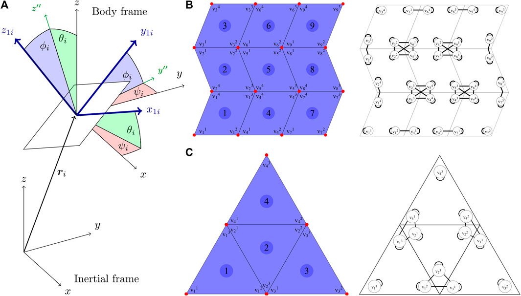
FIGURE 4. (A) Sequence of rotations between the inertial frame xyz and the ith facet body frame x1i y1i z1i. Polygon and vertex numbering scheme, and a graph showing the vertex connectivity for a Miura fold pattern (B) and a pyramidal sail pattern (C).
The origami fold pattern is defined as a set of N polygons, which are themselves a set of ni vertex coordinates, such that the vector of all vertex positions is
The constraint equations are found by first generating an adjacency matrix A, which is a square Nv × Nv matrix, where Nv is the total number of vertices, given by
where AC is the constraint adjacency matrix, defined by:
with all zero rows removed, resulting in an Nv × Nc matrix, where Nc is the number of constraints. For example, if vertices i, j and k are coincident, Eq. 16 leads to the constraint equation 2vi − vj − vk = 0 appearing in the constraint vector C. This procedure allows the multibody dynamics to be formulated for arbitrary fold patterns, where the pattern is defined as a collection of polygons. For an initial state vector q and applied force vector Qa, the differential algebraic system of equations in Eq. 15 is solved for the Lagrange multipliers λ, and the accelerations
Although the notation of this section is somewhat cumbersome this approach has proved convenient for implementing within a mathematical programming environment, as the functions required to generate the required expressions are included in standard libraries and the origami design can be simply input as a list of points.
3.3.2 Ray-Tracing for Solar Radiation Pressure Calculation
To take into account self-shadowing and reflection of light between facets, ray-tracing is used to calculate the path of the incident and reflected radiation, and to then evaluate the resultant force due to SRP on each facet. Ray-tracing is commonly used in computer graphics for accurate rendering of 3D models (Glassner and Jovanovich, 1989). In spaceflight engineering, ray-tracing is used for precise orbit determination when the SRP force needs to be known within a tolerance such that the variation in the optical properties of the spacecraft’s surface lead to unacceptable errors when estimating the orbital position (Darugna et al., 2018). For an origami spacecraft, it is possible that in a certain configuration the entire incident radiation on a perfectly reflective facet could be reflected onto another facet, effectively doubling the force due to SRP on that facet and greatly affecting the system dynamics. Ray-tracing gives a computationally efficient method of calculating these inter-facet reflections and shadowing, and a description of the module is given in this section.
The ray-tracing procedure begins by defining an NR × NR grid of points, evenly distributed within a square region that has a surface normal aligned with the incident radiation direction, and directed at the centre-of-mass of the multibody system. The square region has a spatial dimension DR large enough to completely contain the projected area of the sail within the DR × DR square. Rays are then cast from these points and the resultant force is found by determining whether each ray intercepts a sail facet. These collision calculations are performed using a MATLAB wrapper (Vijayan, 2021) for the OPCODE collision detection library (Terdiman, 2003), which makes use of bounding volume hierarchies. If a ray intercepts a sail facet, the ray is then specularly reflected from the facet’s surface, and the collision detection repeated to determine whether the ray intercepts a further facet. This process is repeated until no further reflections are found. Throughout the ray-tracing calculation, the location of rays which intercept each facet are stored, and the resultant force and torque on each facet is found by summation of the contribution of every intercepted ray, according to Eq. 18, which gives the total force on facet i due to SRP:
Eq. 18 is derived by evaluating Eq. 1 for every incident ray on facet i. The facet area A in Eq. 1 is replaced with
where rij is the position vector of the incidence point of ray j from the centre-of-mass of facet i, and
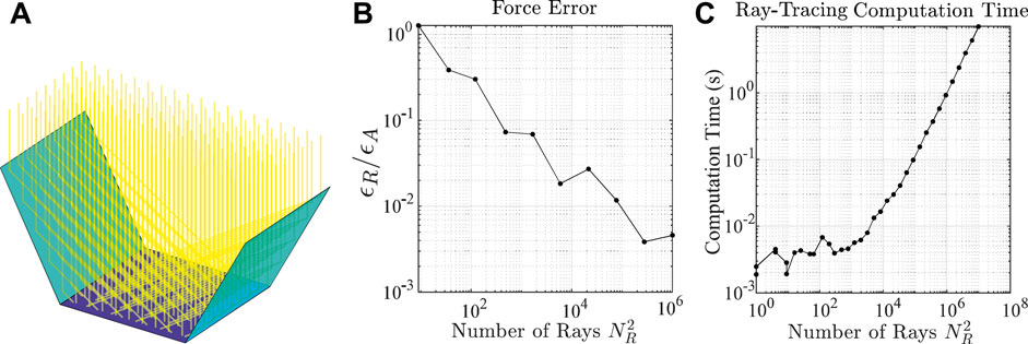
FIGURE 5. Illustration of ray-tracing for an example three-facet OrigamiSat (A), force error (B) and computation time (C) of the ray-tracing module against the number of rays.
3.4 Simulations of Self-Reconfiguring OrigamiSats
The multibody dynamics formulation presented in the previous section is now used to demonstrate through simulation that SRP and local SRM can be used to control the shape reconfiguration of rigid origami structures. In addition to demonstrating the basic principle of SRP triggered shape reconfiguration, these simulations are used to illustrate the limitations of the strategy and to highlight some considerations for the future development of control algorithms for the active shape control of OrigamiSats. As aforementioned, all the simulations are performed using a MATLAB code developed by the authors.
3.4.1 Miura Fold Pattern
The first simulation is of a Miura fold pattern, consisting of a 4 × 4 grid of rhombic unit cells. As discussed previously, the Miura fold is well known to have only one degree of freedom in folding, making it particularly useful for deploying planar structures as the unfolding requires minimal actuation. The sail is 1 × 1 m, with an areal mass density of 10 g/m2, considering the areal mass density of near-term solar sails. Reference to Figure 2B suggests that at this length scale, the time to complete a fold should be on the order of minutes. Additionally, Figure 2B shows that at this length scale the effect of bending resistance for a thin film hinge is insignificant and as such is not considered in the following simulations. The simulation timestep was chosen to be 0.1 s, and the system given in Eq. 15 solved numerically in MATLAB using the ode45 solver, where the applied forces Qa are calculated using the ray-tracing module and the evaluation of Eqs 18, 19. For simplicity, the structure is assumed to be at rest in free space with no other external forces acting upon it. The structure is initially flat and lying in the xy plane, and incident radiation is directed in the − z direction. To ensure the structure folds correctly, the correct pattern of valley/mountain folds for the Miura pattern must be initiated. This is achieved by applying a torque of ±1 × 10⁻⁸ Nm to alternating facets, integrating the equations of motion for one timestep, and then setting the facet velocities and forces to zero before beginning the simulation. This results in a slight angular displacement of the facets which achieves the desired mountain/valley folds and allows the main simulation to proceed. Note that in reality, the correct pattern of mountain and valley folds would be preserved by either the plastic deformation of the creases in the hinge material, or by a physical mechanism. This “fold initiation” is only a concern for the simulation here because the “exactly” flat condition can lead to numerical instability. First, the outer columns of facets are set to be perfectly reflective with ρ = 1, while the middle two columns are perfectly absorbing with ρ = 0. Reflective/absorbing facets are illustrated in all figures as light/dark blue respectively.
The simulation was run for a duration of 100 s and results are shown in Figure 6A, which shows the spacecraft drawn in the centre-of-mass frame at selected timesteps. The spacecraft is seen to completely fold inwards in this time, due to the relatively larger force acting on the outer, reflecting facets. This force acts in the correct direction to effectively fold the single-degree-of-freedom Miura fold pattern. As in the planar simulations, it was thought that by reversing the reflectivity pattern that the folding action could also be reversed. The simulation was repeated, this time with the inner facets perfectly reflective, with results shown in Figure 6B. The folding direction is indeed found to have reversed here. However, after t = 80 s, the folding ceases and the sail instead begins to open and return to the flat configuration. This is due to the inter-facet reflections, as incident radiation is reflected from the central facets and is then absorbed by the outer facets. This increases the force acting on the outer facets enough to reopen the sail. It was found that the sail could still be folded completely if the reflectivity of the central facets is set to zero after a time of approximately 30 s, as the remaining momentum of the facets is enough to complete the fold and there are then no inter-facet reflections to prevent the motion. Animations of the simulation results shown in Figures 6A,B can be viewed in Supplementary Videos S2, S3 respectively.
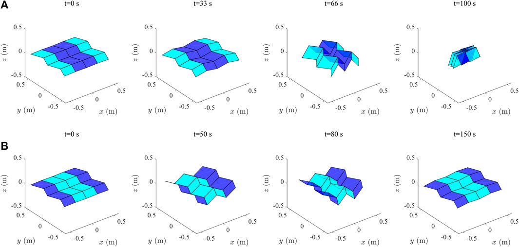
FIGURE 6. (A) Reconfiguration of a Miura fold pattern using SRP. Light blue facets are perfectly reflective and dark blue are perfectly absorbing. (B) Reversing the folding direction by reversing the reflectivity pattern. After 80 s, inter-facet reflections cause the sail to reopen.
3.4.2 Proportional Derivative Shape Control of a Pyramidal OrigamiSat
If the reflectivity of each facet can be individually controlled using RCDs, it would be possible to actively control the shape reconfiguration of an OrigamiSat. This is demonstrated here through simulation of a pyramidal sail design, in which the facet reflectivities can be individually controlled continuously between values of ρ = 0 and 1, again assuming some ideal form of RCD. In attempting to perform this simulation, it was found that the sail’s overall attitude was unstable and it would begin to rotate relative to the incident radiation direction. For simplicity, this instability was removed by constraining the x, y coordinates of the centre facet’s vertices, such that this facet always faced the incoming radiation. This constraint was imposed here to simplify the dynamics for this demonstration of shape control, but in practice control algorithms will be required which combine shape and attitude control requirements.
A triangular sail design is selected, consisting of four triangular facets. The facet and vertex numbering and connectivity, used to generate the equations of motion, are shown in Figure 4C. The areal mass density is again selected as 10 g/m2, and the sidelength of each triangular facet is set to 1 m, again assuming that this scale will give folding times on the order of minutes and that the hinge bending resistance can be ignored. Shape control is achieved through the use of a proportional derivative (PD) controller, where the variables being controlled are the hinge angles of the outer facets, contained in the vector Φ = [ϕ1, ϕ3, ϕ4]. The hinge angles are defined as ϕ = 0 for a facet lying in the xy plane, and positive when the facet folds downwards in the − z direction. It is assumed that the reflectivity of each facet can be continuously varied between zero and one. A PD control law is implemented to determine the required reflectivity values of the outer facets [1, 3, 4], given by:
where the values are constrained to the range [0, 1]. kp and kd are the proportional and derivative control gains respectively, and Φe = Φ − Φref is the vector of angle errors, given by the difference between the current facet angles and the target angles. The derivative term
The simulation is run for a duration of 600 s, with the target angles set to −1 rad for the first 200 s, 1 rad for the next 200 s, and 0 for the final 200 s. The controller was tuned manually, resulting in control gains of kp = 50 and kd = 1200. The control gains were selected by trial and error, by first finding a proportional gain that gave a reasonable rise time, and then finding a derivative gain that eliminated any overshoot. Results of the simulation are shown in Figure 7, showing a plot of the angles of the outer facets, and in Figure 8, which shows the system plotted at 5 s intervals for the first 300 s of the simulation, showing the transition between the first two target configurations. An animation of the simulation can be viewed in Supplementary Video S4. The controller successfully reconfigures the spacecraft between the two target shapes, before returning to the flat position. As seen in Figure 7, there is a slight discrepancy between the angle of facet four and the other outer facets, which is thought to be due to a rounding error in the numerical simulation. As the shape is triangular, the vertex coordinates cannot all be integers. This slight difference in the facet coordinates is then carried through the simulation and the effect amplified by the feedback controller, since each facet is controlled individually.
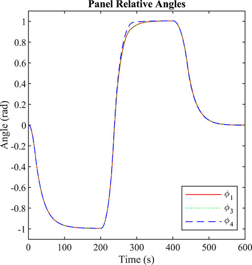
FIGURE 7. Relative angle of outer facets during PD control simulation moving between the three target configurations.
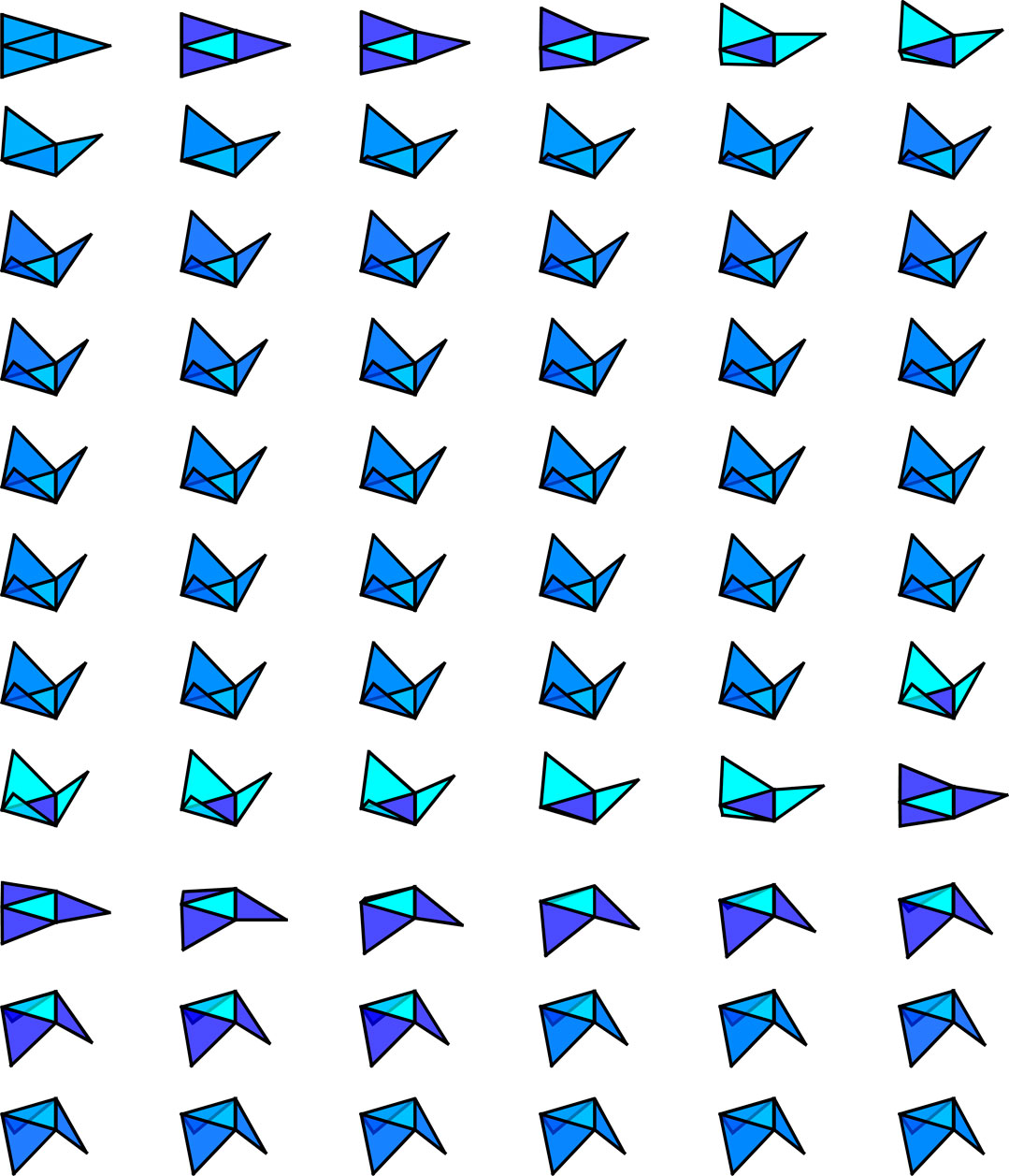
FIGURE 8. Pyramid OrigamiSat plotted at 5 s intervals for the first 300 s of PD control simulation, showing the transition between the first two target configurations. The reflectivity of each facet represented by shade of blue interpolated for values between 0 and 1.
Overall, the simulation has demonstrated that PD control of shape reconfiguration through the use of local SRM is possible, but some limitations have been encountered. Firstly, we again note that the orientation of the central facet was constrained to remain facing the direction of the incident SRP. This constraint was imposed because it was found that otherwise the spacecraft began to tumble. This highlights the need for either an integrated attitude/shape control algorithm, or for a separate attitude control system to maintain attitude stability while shape reconfiguration is performed. A further note is that some knowledge of the shape reconfiguration was assumed a priori when implementing the PD control equation. Specifically, it was assumed that reflectivity patterns of ρ = [1, 0, 1, 1] and ρ = [0, 1, 0, 0] would result in folding in the positive and negative directions respectively. While this was an obvious assumption for this sail design, for more complex origami structures with coupled degrees-of-freedom in folding, the relationship between facet reflectivity patterns and folding behaviour may be difficult to predict. For more complicated origami designs, this relationship could potentially be deduced through simulation by creating a lookup table of possible reflectivity patterns and observing the resulting dynamics, or it may be possible to find analytic expressions for the resulting motion of specific reflectivity patterns. A further level of complexity is introduced here by the fact that the system will have different folding behaviour for a given reflectivity pattern depending on the direction of incoming radiation, i.e., the coupling of the attitude/reconfiguration dynamics further complicates the development of potential control strategies. For this reason it is assumed that an additional attitude control system may be desired for spacecraft of this type, which is capable of maintaining a fixed orientation relative to the Sun vector while the reflective facets are used to enact shape reconfiguration.
A further challenge encountered is that the extent of the shape reconfiguration that can be achieved with this strategy is limited. There is an obvious limit in that, if the outer facets fold over past the vertical position, they then occlude the centre facet and SRP cannot be used to return to a flat position. In practice, it was found through simulation that the achievable angle was less than π/2 rad, with the controller struggling to not overshoot and lose control effectiveness for target angles greater than approximately 1 rad, hence the target value selected for the simulations here. This limit means that for some OrigamiSats, reversible shape reconfiguration would require further actuation in addition to the RCDs. For example, SMPs or SMAs could be used in the hinges of such a spaceraft to actuate the deployment, while SRM could then be used for shape reconfiguration within the achievable angles during normal operation. Of note however is that this limitation depends on the origami folding pattern, as for the Miura pattern of the previous simulation reversible folding was achieved through the use of SRP alone. The need for additional hinge actuation will depend upon the folding degrees-of-freedom of the origami design, and also on whether inter-facet shadowing or reflections break the symmetry of the folding process, as was observed for the Miura fold.
4 Manufacturing
In this section a detailed description on a small prototype manufacturing process is presented. The realised structure does not contain all the hardware needed for the full deployment (such the RCDs integration, power generators and the required PCB), which will be integrated in the future. Activities related to process validation and part qualification for 3D printing for space use is ongoing at the University of Glasgow. The current section is only discussing the proof-of-concept and future work will bring it to space standards. Moreover an orbit demonstration mission can be considered to gain space heritage for the real-size model. All the critical aspects about the assembly and additive manufacturing processes are here described.
The proposed structure is capable of changing its shape by acting on the origami edges giving a different angular displacement of two adjacent facets. Moreover, many constraints were considered for the design process as: the Ultimaker S5 and MakerGear printers available at the University of Liverpool will enforce the maximum printable volume and the printable materials selection which are sufficient for researching about the manufacturing process and build a small prototype. The latter can be scaled up, by harnessing an additive manufacturing multi-DOF machine Jiang et al. (2021): this will open a new paradigm for building large structures at once, avoiding any assembly procedures. On ground testing of the OrigamiSat folding were perform using an external heather while in space it is expected that embedded heaters between the Al-Kapton membrane and the smart material edges will trigger the folding in conjunction with optical changes capability of the facets (i.e., RCDs devices) Here the trade-off analysis to manufacture the origamiSat’s facets is discussed: the main body is made of Al-Kapton, a high reflective material, whose structure is reinforced by printing on top the final origami pattern triangles and hexagons. An elastic filament, the thermoplastic polyurethane (TPU), remained always attached after being printed directly on the Al-Kapton. The Acrylonitrile Butadiene Styrene is carbon fibre (ABS-cc) is added to augment mechanical properties for the folding procedure. Two different patterns have been studied: the “cartilage-like” pattern, where the hinge is composed only of TPU (which is the only material directly attached to the Al-Kapton, due to its chemical compatibility) and a Shape Memory Polymer (4D filament) integrated on its top which makes the mounts or valleys fully stretchable; the other is the mechanical pattern, where rotational hinges are made of ABS-cc. The cartilage-like pattern was selected due to its superior printed accuracy and to enhance the utilization of the Shape Memory Polymer, which guarantee the complete autonomous unfolding movement; the final configuration has the framed structure is realized by combining the TPU and ABS-CC. For the 4D activation a thin film heater and RCDs are embedded for the completely autonomous folding and unfolding procedure.
4.1 Design Process
The OrigamiSat prototype design is initiated by conducting a compatibility material trade-off. The chosen adjacent facets for achieving the aforementioned purpose are just two simple equilateral triangles with the same thickness: as shown in Figure 9, the first design proposal has no mechanical hinges and it designs to be stretchable and bends as “cartilage”. Indeed, the edge, where the crease occurs, is fabricated of TPU 95A elastic material as well as the first layer directly attached on the high reflective material. Different structural materials have been considered such as PLA, ABS and Nylon with the Carbon Fiber (CC) reinforcement to strengthen the structure and maintain the final deployed shape. The whole height of the printed material is 1 mm. The second design proposal considers mechanical hinges on the edges, for connecting two facets. They have two separate parts, which rotate relative to each other: due to the small scale thickness, the parts resulted in being wholly melted while printed. The result is lousy and the same flatness of the previous design configuration is not achieved while folded. The pyramid represents the final and selected configuration in Figure 9 since it is the most straightforward 3D shape that is possible to achieve from equilateral triangles. It combines the TPU 95A, the same structural material mentioned for the previous patterns, and the printable Shape Memory Polymer (SMP) (Esun, 2020) along the edges. This material has demonstrated to recover the printed shape by applying external heating at the activation temperature of 75°C. This configuration could facilitate embedding RCDs devices on the external facets and the implementation of a thin solar cell in the central triangle for powering purposes Section 3.4.2. For the SMP activation, a customised thin-film heater can be inserted between it and the reflective surface material.
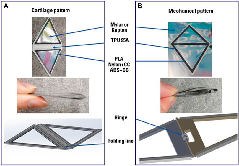
FIGURE 9. Triangle patterns for the deployment mechanism trade off. (A) The cartilage pattern and its bending radius while folded through the folding line. (B) The Mechanical pattern and its bending radius while folded through its mechanism which is a mechanical hinge. Both patterns have been printed alternatively on Mylar or Kapton with the TPU 95A as elastic material and PLA, Nylon+cc or ABS+cc for the structural material.
4.2 Materials
The cartilage pattern is used to evaluate the overall mass and the attachment compatibility and for the reflective surface material trade-off, which for this application are Mylar and Al-Kapton. Al-Kapton has been preferred due to its lower mass and nominal thickness of 25.5 μm. The mass evaluation is presented in Table 1, therefore embedding the 4D material with the TPU and the ABS/cc showed to be the best mass evaluation.
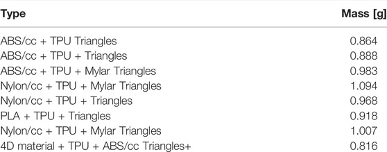
TABLE 1. Cartilage pattern mass evaluation.
PLA has been discarded since it displayed of permanent deformation as a result of the heating process once printed. We compared the pros and cons of using ABS vs. Nylon with CC. The ABS/cc is advantageous for its tensile modulus of 2700 MPa (ISO 527). It is also less fragile and more stable than standard ABS since it has a lower thermal expansion than standard ABS. Moreover, ABS/cc glass transition temperature is 120°C. The main disadvantage of ABS/cc is in its bed temperature around 90°C which can cause detachments while embedding other materials and it is prone to warping failure. Nylon/cc presents a tensile modulus of 500 MPa (ISO 527) and it is a durable material. It is ideal for making parts that require stress. It is beneficial for its high thermal and chemical resistance and low thermal expansion. Moreover, it shows little warping and greater hardness. The main disadvantage of Nylon/cc is in lower moisture absorption than standard nylon and high absorption of humidity. Indeed, the humidity absorption represents a crucial phenomenon, making ABS/cc preferable together with the excellent temperature changes resistance.
All the printed samples have been showed warping, which decreases once the sample is heated up. This phenomenon occurs due to the printer bed warming during the printing phase and the coefficient of thermal expansion, since it is directly attached to the bed with tape where air bubbles are completely removed. TPU 95A is chosen as the first layer directly deposited on the Al-Kapton which shows a well-suited macroscopic attachment even after 10 cycles of heating process for the activation of the 4D edge. The ABS/cc is grooved inside the TPU 95A structure and not only deposited to prevent delamination in the heating and changing shape processes. Due to the different size of the Ultimaker nozzles (0.6 for the ABS/cc and 0.4 for the TPU 95A filaments), the quality settings are slightly different for each material, with a line width of 0.525 and 0.35 mm respectively, with a triangles infill pattern and an infill line width of 0.5 mm.
The 4D material has to be printed separately due to the filament diameter, therefore, a meticulous assembly procedure on the Ultimaker s5 bed has to be followed. The 4D material cross section in Figure 10 presents a lateral step to permit the TPU 95A to be attached completely and to permit the overall structure assembly. The central V shape is designed to permit the fold over the sharper edge, which coincides with the folding line: here is settled to 0.1 mm. Further investigation will be addressed in the future, for evaluating the Out-gassing requirements as well as the Atomic Oxygen erosion.
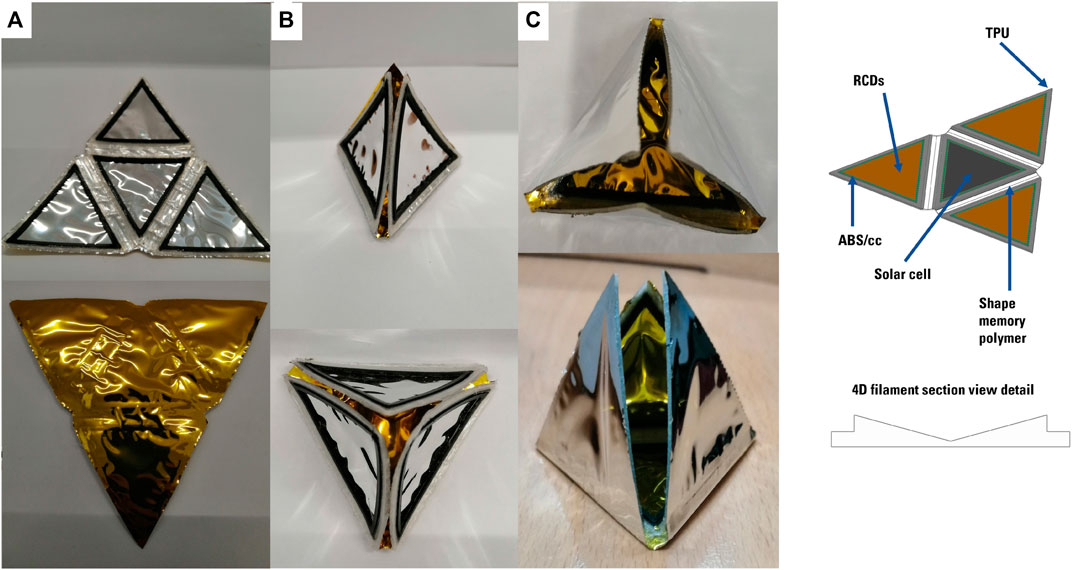
FIGURE 10. Pyramid shape sample in the deployed (A) and folded configurations upward (B) and downward (C) and CAD details.
4.3 Printing Procedure
The 4D material filament diameter is not suitable for the Ultimaker s5, therefore, the self-folding part is realized separately with the MakerGear printer. Before starting the process, the bed is topped up with Dimafix glue. A separated test for confirming the chemical compatibility of different glues applied on Mylar and Kapton has been performed: five different glues have been tested between the two reflective materials and the printer bed. Mylar samples with the Dimafix and Magigoo Original glues are characterized by good compatibility results and few air bubbles are formed with the first one. Then Al-Kapton sheets are tested sequentially with Dimafix, Magigoo Original, Magigoo for HT filament, Magigoo for PA, UHU stick glues. In the first and second samples, air bubbles are present, while in the third, detachments occur as well as a principle of abrasion, which is more visible in the fourth sample; the UHU stick glue causes significant detachments. The corrosion process is notable mainly in the Mylar samples with Magigoo for HT filament and Magigoo for PA, while UHU stick glue causes detachments. The test was performed by heating the samples to 120°C for 30 min, and the results were analysed after 24 h. After the self-folding part is printed, the CAD file is imported in the Cura software, which is that one used for tuning all the settings for the main print in Ultimaker S5. The print starts and will be paused after the first layer of TPU 95A is deposited: this serves as a guide on where to integrate the 4D material part (details shown in Figures 11B). The print is paused and glue is applied on the gaps where the SMP has to be inserted. They are gently positioned correctly and a slight pressure to avoid contour detachments is applied. The print is then resumed, obtaining the final prototype. Before removing the sample, the bed has to reach the ambient temperature.
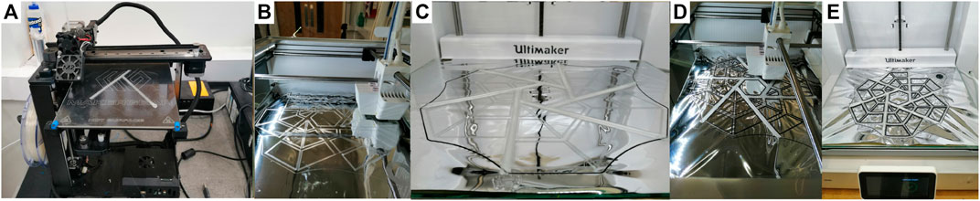
FIGURE 11. Final shape design procedure: (A) Print procedure on the MakerGear printer, (B) Application of the on the Ultimaker s5 bed and first TPU 95A deposition, (C) 4D material integration, (D,E) Finishing the print and final result.
4.4 Pyramid Pattern Prototype and Self-folding Test
In Figure 10 the whole printed, heated, folded processes are shown. Once the sample is removed from the bed, is delicately cut from the remaining Al-Kapton and heated up. To have a better visible control, an electric heater is used, for heating the sample up; then, the sample is deformed just applying an external force, which for the pyramid sample is controlled by hand. The external force has to be applied for at least 10 s. The sample could be folded in both directions. Thereafter, an external heating flat patch has been built with just Copper wire on a Mylar sheet. In Figure 12, the self-deployment procedure is shown: from applying voltage to the wire and rising the temperature from 70 to 90 deg, is possible to achieve a flat configuration (refer to Supplementary Video S5). Note that the test has been performed in a considerable large room and an isolation box has to be designed to prevent heat dispersion, around the sample.
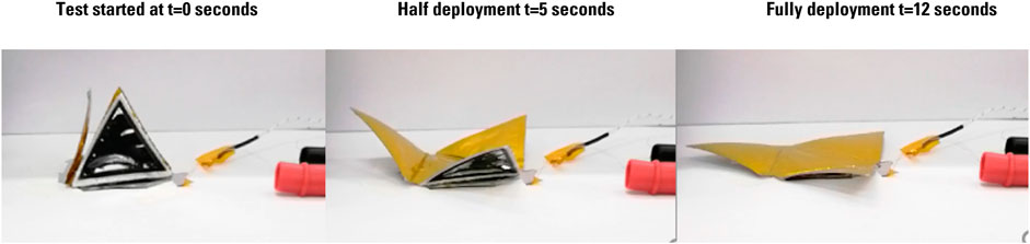
FIGURE 12. Sequential deployment of the pyramid sample with an external flat heater on the base.
4.5 Final Origami Pattern Design
The chosen final shape comes from the original origami of Zirbel et al. (2013) with few modifications applied on the created gaps. The hexagon has a length of 3 cm due to the printer bed volume constraint and has a total thickness of 1 mm. In Figure 13 is possible to see the top view of the final Origami CAD. There are three different gaps between the TPU 95A and ABS/cc insertions, which are directly related to the pattern design: the blue gaps are valleys and are the only ones filled with the 4D material and they have a dimension of 2πt for achieving a complete folding of 180 deg, therefore, they coincide with the active edges; the radial mountain gaps permit the complete folding, therefore any additive material insertion is permitted and a slot of 1 mm is left. Other slots which coincide with mountains and valleys are going to be folded around the central hexagon, therefore any additive material is allowed and a gap of πt is considered to achieve a complete folding of 60°. Details about the CAD files of TPU 95A, the 4D material, the ABS/cc insertion are shown in Figure 14 c-f.
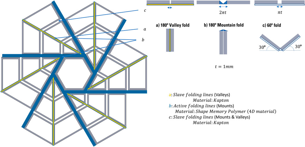
FIGURE 13. Final origami pattern details. (A) In yellow all the valley folds where only the Al‐Kapton is exposed, (B) In Blue the Shape Memory Polymer mount folds which are activating the reconfiguring process, (C) Mixed mounts or valley folds where only Al‐Kapton is exposed.
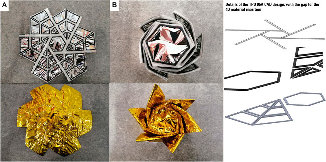
FIGURE 14. Final origami solar sail configuration fully deployed (A) and folded (B). CAD details of all the parts: the 4D material, the ABS-CC and the TPU 95A one.
4.6 Final Origami Pattern Manufacturing
In Figure 11 the whole printing and assembly processes are shown. Starting from the printing of the 4D material in the MakerGear printer, applying the Al-Kapton in the Ultimaker bed and heating up it, continuing with the first layer of the TPU 95A print to use it as a guide for later applying with the glue the 4D material, the first layer deposition procedure has ended when the shape is contoured with the ABS/cc filament. To apply the 4D material the print has to be paused, and resumed once the integration process is ended. Once the print is ended we need to wait until the bed is at the ambient temperature to remove the sample. To change the shape, this pattern has to be heated and external paper clips are used to maintain the shape when is still heating up. Afterwards, the sample is removed from the heater and is constrained with a wire around the external perimeter, until it cools down to ambient temperature: this process requires 10 min. The folded and unfolded origami pattern is shown in Figure 14 where the folded and unfolded configuration are captured. Note that after the heating process it is possible to achieve a complete flat surface due to the self-deployment capability (refer to Supplementary Video S6).
5 Conclusion
In this article, the use of combined thermo-optical properties for triggering shape reconfiguration of an OrigamiSat has been investigated. While the use of a swarm of OrigamiSat is envisaged to enable a new paradigm towards mission design, we focused on a the numerical modelling and manufacturing process of a single OrigamiSat. We first explored the use of Surface Reflectivity Modulation (SRM) control on the facet to regulate the intensity of Solar Radiation Pressure (SRP) forces acting on the facets. It was shown that for a reflective flat square facet with a fixed edge, the time to complete a fold of π/2 rad under the influence of SRP is on the order of minutes for areal mass densities on the order of 10 g/m2 and length scales on the order of metres. Further, it was shown that for a hinge constructed of the same thin film material as a conventional solar sail, the bending resistance of this hinge can be neglected above a critical length scale, due to the advantageous scaling of the force as a result of the SRP compared to the hinge resistance. Results of planar simulations show that folding can be induced, and the direction of folding reversed by controlling the SRM of linked, rigid facets. However, long chains of connected facets may be difficult to control in this manner, due to the large number of rotational degrees of freedom in the system.
A method for generating the multibody equations of motion for 3D rigid origami systems was developed, and used to demonstrate the use of SRM to enact shape reconfiguration of 3D origami structures in free space. Simulations have shown that shape control with this strategy is possible in principle, but the degree of control that can be achieved depends upon a number of factors: the kinematics of the origami pattern design and in particular the degrees of freedom in folding of the design; the effect of inter-facet reflections and shadowing; and the ability to decouple the attitude dynamics from the shape reconfiguration, either through a dedicated attitude control system or the development of an integrated shape and attitude control algorithm. Active shape control was demonstrated for a simple triangular design with a PD control law, though the results here suggest that in practice additional actuation will be required to achieve deployment and shape control within the full range of possible motion for many origami designs. Future work could include the development of integrated attitude/shape control algorithms as simulations have shown that coupling of the attitude and folding dynamics will be a challenge during shape reconfiguration. This could be achieved through the use of the RCDs to modify the OrigamiSat’s centre-of-pressure, though due to the coupled attitude/folding dynamics it is likely that further actuation may be required.
We then explored the use of the Shape Memory Polymer (SMP) (or 4D filament) applied directly on Al-Kapton, material typically used for solar sails film for the actuation of the edges. The TPU 95A is used for the rest of the whole OrigamiSat structure during the first layers deposition: is an elastic material which compatible with Al-Kapton and showed to be well attached to its surface even after a full thermal cycle for activating the 4D filament. The ABS/cc is used to augment the mechanical properties of the structure and is embedded in the TPU 95A. Comparison between mechanical hinges and cartilage-like edges were traded-off. The latter shows to be preferable because of its printed accuracy and to enhance the utilization of the Shape Memory Polymer, which guarantee the complete autonomous unfolding movement. The thin film heater requires the power collected by six triple junctions solar cells in the case of the pyramid, while for the full scale architecture, the total number of cells is just the double, as the edge is growing in one dimension only. This design enables deployment of the folded OrigamiSat when exposed to an external heat source that activated the 4D material. This is an alternative design compared to traditional solar sail deployments that involve booms. It is important to notice that not all the edges have to be manufactured with 4D filament to trigger the deployment thus making the structure lighter. The numerical experiments show that a hybrid thermo-optical 4D printed OrigamiSat is required to enable reversible shape-changing between several configurations, enabling multi-operational functions.
Data Availability Statement
The original contributions presented in the study are included in the article/Supplementary Material, further inquiries can be directed to the corresponding author.
Author Contributions
AR and BR have contributed equally specifically BR is the lead of Section 3 and AR is the lead of Section 4. SS is the PI of the project and PP is the CoI. SS and PP have contributed to Sections 1, 2, Intro, Conclusions and Abstract. GB and CM have mainly contributed on Section 3. JR, AS, SB, and OM have contributed equally providing in-kind support and interpretation of results.
Funding
This project was funded by the Connected Everything II feasibility study Grant Ref: EP/S036113/1 led by SS at University of Liverpool in partnership with the Japanese Aerospace Exploration Agency and Oxford Space Systems. The University of Glasgow participated as an external collaborator. CM is supported by the Royal Academy of Engineering under the Chair in Emerging Technologies scheme.
Conflict of Interest
Author AR and JR were employed by the company Oxford Space Systems.
The remaining authors declare that the research was conducted in the absence of any commercial or financial relationships that could be construed as a potential conflict of interest.
The authors declare that this study received support from Oxford Space Systems. The funder had the following involvement in the study: interpretation of results
Publisher’s Note
All claims expressed in this article are solely those of the authors and do not necessarily represent those of their affiliated organizations, or those of the publisher, the editors and the reviewers. Any product that may be evaluated in this article, or claim that may be made by its manufacturer, is not guaranteed or endorsed by the publisher.
Supplementary Material
The Supplementary Material for this article can be found online at: https://www.frontiersin.org/articles/10.3389/frspt.2022.876585/full#supplementary-material
Supplementary Video S1 | Results of simulation for a series of linked, rigid panels with alternating surface reflectivity.
Supplementary Video S2 | Results of simulation for a Miura fold pattern OrigamiSat with reflective outer panels.
Supplementary Video S3 | Results of simulation for a Miura fold pattern OrigamiSat with reflective inner panels.
Supplementary Video S4 | Results of simulation of a pyramidal OrigamiSat with variable reflectivity panels, demonstrating PD shape control between target configurations.
Supplementary Video S5 | Deployment test of the pyramid shape 4D printed prototype.
Supplementary Video S6 | Deployment test of the final origami solar sail 4D printed prototype.
References
Baraff, D. (1996). “Linear-time Dynamics Using Lagrange Multipliers,” in Proceedings of the 23rd Annual Conference on Computer Graphics and Interactive Techniques, SIGGRAPH 1996, 137–146. doi:10.1145/237170.237226
Borggräfe, A., Heiligers, J., Ceriotti, M., and McInnes, C. R. (2015). Shape Control of Slack Space Reflectors Using Modulated Solar Pressure. Proc. R. Soc. A 471, 20150119. doi:10.1098/rspa.2015.0119
[Dataset] Bovesecchi, G., Corasaniti, S., Costanza, G., and Tata, M. E. (2019). A Novel Self-Deployable Solar Sail System Activated by Shape Memory Alloys. Aerospace 6, 78. doi:10.3390/aerospace6070078
Ceriotti, M., Harkness, P., and McRobb, M. (2014). Variable-Geometry Solar Sailing: The Possibilities of the Quasi-Rhombic Pyramid. Adv. Sol. Sail. 899, 899–919. doi:10.1007/978-3-642-34907-2_54
Darugna, F., Steigenberger, P., Montenbruck, O., and Casotto, S. (2018). Ray-tracing Solar Radiation Pressure Modeling for QZS-1. Adv. Space Res. 62, 935–943. doi:10.1016/j.asr.2018.05.036
[Dataset] Esun (2020). Esun 4d Filament Product Datasheet. Available at: https://www.esun3d.net/products/487.html (Accessed Januray 15, 2022).
Farrés, A., Heiligers, J., and Miguel, N. (2019). Road Map to L4/l5 with a Solar Sail. Aerosp. Sci. Technol. 95, 105458. doi:10.1016/j.ast.2019.105458
Glassner, A., and Jovanovich, H. B. (1989). An Introduction to Ray Tracing. Morgan Kaufmann Series in Computer Graphics and Geometric Modeling. San Francisco: Elsevier Science.
[Dataset] Inglesias, K. K. (2020). Origami-based Self-Deployable Thin Membrane for Spacecraft. MSc Thesis. University of Colorado Boulder.
Jiang, J., Zhong, R., and Newman, S. (2020). A Review of Multiple Degrees of Freedom for Additive Manufacturing Machines. Int. J. Comput. Integr. Manuf. 34. doi:10.1080/0951192X.2020.1858510
Karmakar, S., and Mishra, A. (2021). Deployable SMA-Based Light Solar Sail Prototype. Adv. Astronaut. Sci. Technol. doi:10.1007/s42423-021-00080-7
Lai, K., Chen, W.-T., Wu, Y.-H., Chen, Y.-F., and Tsai, J. (2019). “3d-printed and Pdlc-Tuned Corner Cube Retroreflector for Sunlight Communication,” in 2019 International Conference on Optical MEMS and Nanophotonics (OMN). doi:10.1109/omn.2019.8925163
Larson, W. J., and Wertz, J. R. (1992). Space Mission Analysis and Design. Dordrecht: Kluwer Academic Publishers.
[Dataset] Ma, D., Murray, J., and Munday, J. N. (2016). Controllable Propulsion by Light: Steering a Solar Sail via Tunable Radiation Pressure. Communication. 5, 1600668. doi:10.1002/adom.201600668
Macdonald, M., and McInnes, C. (2016). Solar Sail Science Mission Applications and Advancement. Adv. Space Res. 48 (11), 1702–1716. doi:10.1016/j.asr.2011.03.018
Malka, R., Desbiens, A. L., Chen, Y., and Wood, R. J. (2014). “Principles of Microscale Flexure Hinge Design for Enhanced Endurance,” in IEEE International Conference on Intelligent Robots and Systems, 2879–2885. doi:10.1109/iros.2014.6942958
McInnes, C. R. (1999). Solar Sailing: Technology, Dynamics, and Mission Applications. 1 edn. Berlin: Springer-Verlag.
McPherson, B. N., and Kauffman, J. L. (2019). “Dynamics and Estimation of Origami-Inspired Deployable Space Structures : A Review,” in AIAA Scitech 2019 Forum, 1–18. doi:10.2514/6.2019-0480
Miyazaki, Y., and Iwai, Y. (2004). “Dynamics Model of Solar Sail Membrane,” in 14th Workshop on Astrodynamics and Flight Mechanics.
Morgan, J., Magleby, S. P., and Howell, L. L. (2016). An Approach to Designing Origami-Adapted Aerospace Mechanisms. J. Mech. Des. 138, 2–10. doi:10.1115/1.4032973
Natori, M. C., Sakamoto, H., and Katsumata, N. (2015). Conceptual Model Study Using Origami for Membrane Space Structures – a Perspective of Origami-Based Engineering. Bull. Jpn. Soc. Mech. Eng. 2, 1–15. doi:10.1299/mer.14-00368
Nishiyama, Y. (2012). Miura Folding: Applying Origami to Space Exploration. Int. J. Pure Appl. Math. 79, 269–279.
Okaro, I. A., Jayasinghe, S., Sutcliffe, C., Black, K., Paoletti, P., and Green, P. L. (2019). Automatic Fault Detection for Laser Powder-Bed Fusion Using Semi-supervised Machine Learning. Addit. Manuf. 27, 42–53. doi:10.1016/j.addma.2019.01.006
Okuizumi, N., and Yamamoto, T. (2009). Centrifugal Deployment of Membrane with Spiral Folding: Experiment and Simulation. J. space Eng. 2, 41–50. doi:10.1299/spacee.2.41
Ono, G., Matsumoto, J., Mimasu, Y., Endo, T., Yokota, R., Miyauchi, M., et al. (2013). Development of Mission Devices and Sub-systems on Sail for World’s First Solar Power Sail Ikaros. J. Space Technol. Sci. 27, 38–53. doi:10.11230/jsts.27.1_38
Peraza Hernandez, E. A., Hartl, D. J., and Lagoudas, D. C. (2019). Active Origami Modeling, Design, and Applications. Cham: Springer International Publishing.
[Dataset] Russo, A. (2020). Multi-functional Self Reconfigurable Robotic Arm (Ramses) and Adjoined Solar Panel Preliminary Design for Lunar Entry Approach Platform for Research on Ground. MSc Thesis. Politecnico di Milano.
Soldini, S., Colombo, C., and Walker, S. (2016). The End-Of-Life Disposal of Satellites in Libration-point Orbits Using Solar Radiation Pressure. Adv. Space Res. 57, 1664–1679. doi:10.1016/j.asr.2015.06.033
Soldini, S., Masdemont, J. J., and Gómez, G. (2019). Dynamics of Solar Radiation Pressure-Assisted Maneuvers between Lissajous Orbits. J. Guid. Control, Dyn. 42, 769–793. doi:10.2514/1.G003725
Stohlman, O. R., Fernandez, J. M., Dean, G., Schneider, N., Kang, J. H., Barfield, R., et al. (2020). “Advances in Low-Cost Manufacturing and Folding of Solar Sail Membranes,” in AIAA Scitech 2020 Forum, 1–19. doi:10.2514/6.2020-2167
Takao, Y. (2020). Active Shape Control of Spinning Solar Sails for Orbital Maneuvers. Ph.D. Thesis. Tokyo: University of Tokyo.
[Dataset] Terdiman, P. (2003). OPCODE Optimized Collision Detection Library (Version 1.3). Available at: http://www.codercorner.com/Opcode.htm.
[Dataset] Vijayan, V. (2021). Ray-casting for Deformable Triangular 3D Meshes (Version 1.0.2). Available at: mathworks.com/matlabcentral/fileexchange/41504-ray-casting-for-deformable-triangular-3d-meshes.
Wu, R., Roberts, P. C. E., Lyu, S., Soutis, C., Zheng, F., Diver, C., et al. (2018). Rigidisation of Deployable Space Polymer Membranes by Heat-Activated Self-Folding. Smart Mater. Struct. 27, 105037. doi:10.1088/1361-665x/aadc72
Zhang, Q., Wommer, J., O’Rourke, C., Teitelman, J., Tang, Y., Robison, J., et al. (2017). Origami and Kirigami Inspired Self-Folding for Programming Three-Dimensional Shape Shifting of Polymer Sheets with Light. Extreme Mech. Lett. 11, 111–120. doi:10.1016/j.eml.2016.08.004
Zhang, X., and Zhou, C. (2017). Dynamic Analysis of Spinning Solar Sails at Deployment Process. Chin. J. Aeronautics 30, 1719–1728. doi:10.1016/j.cja.2017.08.006
Keywords: solar sails, 3D printing, additive manufacturing, shape memory polymers, reconfigurable structures, origami robotics
Citation: Russo A, Robb B, Soldini S, Paoletti P, Bailet G, McInnes CR, Reveles J, Sugihara AK, Bonardi S and Mori O (2022) Mechanical Design of Self-Reconfiguring 4D-Printed OrigamiSats: A New Concept for Solar Sailing. Front. Space Technol. 3:876585. doi: 10.3389/frspt.2022.876585
Received: 15 February 2022; Accepted: 09 May 2022;
Published: 31 May 2022.
Edited by:
Angel Flores Abad, The University of Texas at El Paso, United StatesReviewed by:
Alessandro Ceruti, University of Bologna, ItalySaptarshi Bandyopadhyay, NASA Jet Propulsion Laboratory (JPL), United States
Copyright © 2022 Russo, Robb, Soldini, Paoletti, Bailet, McInnes, Reveles, Sugihara, Bonardi and Mori. This is an open-access article distributed under the terms of the Creative Commons Attribution License (CC BY). The use, distribution or reproduction in other forums is permitted, provided the original author(s) and the copyright owner(s) are credited and that the original publication in this journal is cited, in accordance with accepted academic practice. No use, distribution or reproduction is permitted which does not comply with these terms.
*Correspondence: Stefania Soldini, Stefania.Soldini@liverpool.ac.uk
†These authors have contributed equally to this work and share first authorship