
Advanced Study of Spray Cooling: From Theories to Applications
by
Tianshi Zhang
1,2,3,4,*,
Ziming Mo
1,2,
Xiaoyu Xu
1,2,4,
Xiaoyan Liu
1,2,4,
Haopeng Chen
1,2,4,*,
Zhiwu Han
2,3,
Yuying Yan
5 and
Yingai Jin
1,2,4,* 1
College of Automotive Engineering, Jilin University, Changchun 130022, China
2
State Key Laboratory of Automotive Simulation and Control, Jilin University, Changchun 130022, China
3
Key Laboratory of Bionic Engineering (Ministry of Education), Jilin University, Changchun 130022, China
4
Yibin Research Institute of Jilin University, Yibin 644000, China
5
Faculty of Engineering, University of Nottingham, Nottingham NG8 1BB, UK
*
Authors to whom correspondence should be addressed.
Energies 2022, 15(23), 9219; https://doi.org/10.3390/en15239219
Submission received: 9 November 2022
/
Revised: 29 November 2022
/
Accepted: 30 November 2022
/
Published: 5 December 2022
Abstract
:With the continuous integration and miniaturization of electronic devices, the heat transfer of the electronic devices continues to surge. This means that thermal management equipment with higher heat flux cooling capacity is required to maintain its normal operation. This paper systematically reviews the progress of spray cooling. In the first part, the thermal dissipation mechanism of spray cooling in the non-boiling regime and boiling regime are summarized, and the correlation formula of heat transfer is summarized. In the second part, the influencing factors of various parameters of the nozzle are summarized, the experimental research and numerical simulation research are summarized separately, and some means and methods to strengthen heat transfer are listed. In the third part, we summarize the current application research of spray cooling in some hot new fields, including electronic technology, aerospace, biomedicine, battery safety, etc. The research prospects and challenges in these fields are highlighted. This research provides a timely and necessary study of spray cooling.
1. Introduction
In the past three decades, with the continuous development of electronic devices, miniaturization, integration, high heat flux has become the main characteristics of electronic products [1,2]. In order to save costs and reduce product packaging volume, the assembly and integration density of commercial electronic equipment components is rapidly increasing. With better performance and increased power, the heat production per unit area is also higher. When element temperatures exceed their normal operating range, every 10 °C increase in temperature results in a 50% decrease in system reliability [3,4]. The heat flux value of a high-end CPU can reach 1 W/cm2, while the heat flux on a hot spot has reached 1000 W/cm2 [5]. If the heat cannot be dispersed in time, it has a serious impact on the performance of electronic components, which fundamentally limits the improvement of working components of high-power electronic equipment. This problem has become one of the major obstacles to the development of electronic products. Therefore, refrigeration devices of electronic products need to achieve lower surface temperatures and uniform heat removal by using less coolant flow, making the cooling surface have no thermal contact resistance and other requirements. This is a big challenge for traditional cooling methods.
At present, among many cooling methods, liquid cooling is the inevitable trend to enhancing the thermal dissipation problem of electronic devices [6,7,8]. The critical high flux (CHF) of spray cooling is very large, which leads to the much higher heat dissipation capacity of spray cooling than that of water cooling under the same conditions. Under open conditions, the CHF of spray cooling reaches 1000 W/cm2. This is because the spray droplets impact the liquid film and produce strong disturbance, which makes the spray cooling have very strong convective heat transfer and phase heat transfer ability [9]. Spray cooling can effectively prevent the liquid from escaping from the surface, especially during the intense boiling stage. In addition, spray cooling has the characteristics of small surface temperature gradient, less demand for spray cooling medium and low surface superheat. Based on these characteristics, spray cooling has become the key research direction of current cooling technology [10].
Spray cooling technology is very complex, and can be affected by many factors, such as working flow rate, coolant type, pressure, injection speed and angle, surface characteristics, etc. Improving some of these parameters, or adding new technologies, will make a great change in thermal dissipation ability. For example, Lin [11] found that when the temperature of a spray surface was lower than 30 °C, the heat transfer coefficient (HTC) with a spray distance of 25 mm was 60% higher than that with a spray distance of 10 cm. Salman [12] used deionized water as a cooling medium, improved the flat surface, and improved the heat transfer enhancement rate by 80% under a temperature difference of 20 K. Therefore, spray cooling has great space for development. Research on the mechanism of spray cooling has become the key to developing spray cooling technology.
Moreover, the problem of cooling is not only confined to the electronics industry. Since the 1990s, advances in medical equipment, satellite and spacecraft equipment, and electric vehicle power battery equipment have been limited by this problem. At present, researchers have actively explored the application of spray cooling in the fields of electronics, aerospace, medicine, battery thermal management and so on, and played a role in actual production and life. People are also currently studying spray cooling to inhibit the thermal runaway of power batteries [13]. In medicine, spray cooling is widely used to protect the skin from heat damage during laser treatment [14].
Unlike previous reviews on spray cooling [1,4,6], the highlights of this paper are mainly in two aspects. In the first aspect, this paper explains the thermal dissipation mechanism of spray cooling in non-boiling and boiling regimes, summarizes the correlation formula for heat transfer, introduces the influencing factors of various parameters on the nozzle, and lists some means and methods to strengthen heat transfer. In the second aspect, in addition to the field of electronic technology, this paper also summarizes the application of spray cooling in new areas such as aerospace, biomedicine and battery safety.
2. Mechanism and Theories of Spray Cooling
The thermal dissipation process of spray cooling mainly includes evaporation of liquid film, enhanced perturbation of liquid film by droplet impact, convective heat transfer and evaporation. Scholars have conducted a lot of theoretical research on the mechanism and process of spray cooling.
When the pressure is constant and the temperature of hot surface is below the boiling point of the cooling medium, the spray cooling is in a non-boiling regime, in which forced convection and evaporation of thin liquid film are the two dominant heat transfer modes. In recent years, domestic and foreign scholars have carried out the following research on the mechanism and process of spray cooling in a non-boiling regime. In 1979, Bonacina et al. [15] used secondary deionized water as a cooling medium and found that although the cooling medium could dissipate a high heat flux in a non-boiling regime, only a small proportion of the cooling medium completely engaged the heat transfer process, and the vast majority of cooling medium did not completely engage the heat transfer function. They believed that the heat of the surface to be cooled is transferred from the surface to the interior of the medium through heat conduction, making the medium evaporate. Therefore, the heat flux increases with the expansion area of the medium. In 1998, Oliphant [16] experimentally compared the performance of jet impingement cooling and spray cooling in a non-boiling regime. The research showed that the heat transfer performance of the jet method mainly depended on the velocity and number of impinging jets. The mass flow rate of spray cooling significantly influenced its heat transfer effect, and droplet velocity was also an important factor. In 2005, Fabbri [17] carried out experiments using deionized water as a cooling medium. The study showed that in the non-boiling regime, the liquid film on the heat exchange surface could be divided into laminar and turbulent layers, and the heat dissipation capacity was improved with the decrease in the thickness of the laminar layer. They also found that injection height had a greater effect on film thickness than injection pressure. In 2006, using FC-72 as the cooling medium, Pautsch [18] studied the heat transfer performance of single-nozzle and four-nozzle configurations in a non-boiling regime, then calculated the thickness of the film with total internal reflection, a non-invasive optical technique. They observed the thickest liquid film in the regime with the worst heat transfer performance of the four-nozzle array, which was consistent with the qualitative imaging results. For a single nozzle, the increase in heat load did not affect the film thickness. In 2009, Si et al. [19] built an experimental open spray cooling system in which the heat flux was kept constant with room temperature, and spray cooling was kept in a non-boiling regime by controlling the surface temperature of the heat source. The experimental results showed that forced convection was the main heat exchange mode in the boiling regime. The inlet pressure of the nozzle had less effect on the heat transfer process, while the injection height was a much more important influencing factor in the liquid film’s evaporation and the convective heat transfer. In 2010, Wang [20] concluded through experiments that the heat transfer mechanism of spray cooling in non-boiling regimes included heat convection and liquid film evaporation. The increase in wall temperature increased the rate of film evaporation and enhanced the degree of heat transfer. Moreover, the thermal dissipation ability was improved with the increase in mass flux. In 2020, Chen [21] believed that the thickness of liquid film was not uniform along the heat transfer surface, which presented a state of thinness in the middle and thickness on both sides. Too thin or too thick liquid film was not conducive to heat transfer. Therefore, the main approach to improving the thermal dissipation capacity in the non-boiling regime was to keep the liquid film at the most suitable thickness.
When the pressure is constant and the temperature of heat exchange surface is above the boiling point of the working fluid, the spray cooling is in nucleate boiling regimes. The specific process is shown in Figure 1A. At this time, bubbles are generated, and phase change heat transfer occurs. At present, domestic and foreign scholars have mainly put forward the following academic views and conducted a lot of preliminary work on the heat exchange process and mechanism of spray cooling in boiling regimes.
In 1976, Mesler et al. [22] studied the mechanism of secondary nucleation in nucleated boiling regime when liquid films existed on the heating surface. In 1996, Yang et al. [23] studied the mechanism of spray cooling in boiling regime. Long-distance microscopic observation revealed that boiling bubbles appeared first at the surface edge and then gradually spread over the entire heated surface. They said the phenomenon occurred because the liquid membrane was constantly buffeted and still absorbed heat as it moved from the center to the edge. The experimental results also showed that the heat transfer coefficient in nucleate boiling regime was larger than that in saturated pool boiling. This was because spray cooling not only improved the heat dissipation efficiency through forced convection but, more importantly, greatly improved heat dissipation efficiency through phase transition including nuclear boiling on heated surfaces and nuclear boiling caused by secondary nucleation. In 1988, Pais et al. [24] summarized previous research results and found that the previous experimental results varied greatly with changes in nozzle characteristics. They established a preliminary analysis model, assuming the droplet surface temperature to be saturated, and found that heat transfer was enhanced with thinner liquid film. Therefore, it was concluded that thinning the liquid film was also an effective measure for improving heat exchange efficiency in the boiling area of spray cooling. Researchers also studied the impact of atomizing nozzles on the CHF. It was pointed out that the entrainment of droplets by steam would cause the lack of liquid on the surface of the heat sink, thus limiting the CHF. In the experiment, when the superheat was 20 °C, the maximum heat flux obtained was 1180 W/cm2.
In 2002, Rini et al. [25] used a charge-coupled device to visually observe the surface of a thin diamond heater. They observed the growth of bubbles on the wall and inside the liquid film in the spray cooling boiling regime and the collision behavior of high velocity droplets on bubbles. Experiments showed that the number of secondary nuclei in the boiling regime was related to droplet flux and the temperature of the hot surface. On the condition of high flux, 85% of the vaporized nuclei observed experimentally belonged to this category. With the increase of droplet flux, both bubble cycle and bubble lifetime were shortened. However, the percentage of nucleate boiling caused by the heated surface and secondary nucleation in the total heat flux remained unchanged, which was maintained at about 50%. In addition, the increase in droplet flux can increase turbulent mixing, thus the efficiency of heat transfer through convection and direct evaporation also increased. In 2005, Horacek and Kiger et al. [26] proposed a three-phase contact line length (CLL) mechanism about the heat transfer. In the experiment, a micro heater array was used to observe the wall heat transfer process, and a total internal reflection technology was used to visualize the gas–liquid interface. The results showed that the wall heat flux in the boiling regime was significantly influenced by the three-phase contact line’s length between solid, gas and liquid, and the wetting area fraction of liquid on the hot surface was not an influencing factor on the heat flux. Increasing the superheat of the hot surface led to the lengthening of CLL, and when the heat flux reached the CHF, the corresponding length of CLL reached its maximum. In 2016, Wang et al. [20] considered the influence of liquid film surface tension, gravity and gas–liquid conversion in spray cooling. They found that process of droplets collision was very significant for forming a complete liquid film and promoting the heat transfer. Furthermore, they believed that the heat transfer process could be divided into four stages, the stage before reaching the surface to be cooled, the stage of forming a liquid film, the stage of extending the liquid film and the stage of breaking the liquid film. Among them, the whole process was dominated by forced convection heat transfer, and other heat transfer forms were supplementary. In 2019, Lin [11] found that the heat flux would significantly increase after the spray cooling entered the nuclear boiling regime. However, when the CHF was reached, the heat transfer efficiency deteriorated with the increase in input power. In 2020, Cai [27] studied the relevant characteristics of wall liquid film in a spray cooling single-phase regime and nucleate boiling regime. They found that the wall membrane was thinner and the velocity lower in the nucleate boiling regime, as shown in Figure 1C. In addition, they believed that in the nucleate boiling regime, the enhancement of thermal dissipation was because of the bubble nuclei on the wall membrane or heated surface, and that small droplets punctured vapor bubbles to crease the nucleation frequency of the bubbles [28]. This section is divided by subheadings. It should provide a concise and precise description of the experimental results, their interpretation, as well as the experimental conclusions that can be drawn.
Figure 1.
(A): Heat transfer mechanism in nucleate boiling regions [29]. (B): Using a total internal reflection technique to visualize and measure the liquid–solid contact area and the three-phase contact line length [26]. (a) undergoes a total internal reflection, while light incident on the SiO2/liquid interface is transmitted (b–d). Most of the light (96%) striking the liquid/vapor interface is transmitted into the liquid and subsequently is scattered by a combination of reflection at a sloped interface (c) or refraction into the vapor (d). Places where the liquid surface is completely parallel to the SiO2 surface will reflect the light to the camera, but these are typically confined to regions smaller than the image resolution. (C): The thickness distribution of wall film with q = 50 W/cm2 (a); q = 170 W/cm2 (b) [27].

Some researchers have found that when the liquid flows out of the nozzle, it starts to break down. Droplets of different diameters, velocities, and trajectories are formed before hitting the surface. If the droplet’s average diameter can be used instead of the complete droplet diameter distribution to describe the spray characteristics, it would be of great convenience to the research. While a variety of definitions of the term “average diameter” have been suggested, this paper uses the definition suggested by R. A. Mugele and H. D. Evans [30], who saw it as the upper bound equation based on the “normal” and Gaussian differential equation, used as the standard to describe droplet size distribution. They also standardized the symbolic representation of the droplet. By using the average diameter, we presume that the spray, which consists of droplets with the same diameter, could approximately represent the actual spray. I. Mudawar and W. S. Valentine [31] found that the average diameter can retain other relevant characteristics in an actual spray situation. The Sauter mean diameter (SMD) is mean diameter with the same volume ratio as the whole body. Diameter is expressed by the following Formula (1):
where is the number of droplets in diameter .
Another mean diameter widely used is the volume median diameter (VMD) , which refers to the midpoint droplet size. There is another diameter [32], which uses the mass conservation equation to calculate droplet diameter under certain working conditions from the known injection velocity and application frequency. The calculation formula is as follows (2), (3):
or
where : throttle hole diameter; : velocity of liquid through the throttle hole; : pulse frequency; : liquid density; : mass flow through the throttle orifice.
The spray pressure, flow rate, number of nozzles and distribution mode can all affect the value of the average diameter. Researchers at home and abroad have conducted several fitting studies on the average diameter and the true diameter, which are summarized as the following in Table 1:
Most of the above models take into account the effect of gravity. Once they are applied to the gravity-free and temperature-differentiated space environment, the accuracy of the models declines significantly. There is an urgent need to increase the correction on these models in.
To understand the spray mechanism, so as to promote the development and application of spray cooling, researchers predicted the thermal dissipation process of spray cooling based on experimental and theoretical results, and then derived some experimental correlations and mathematical models.
In 2008, Jia [40] established a mathematical model of spray cooling film thickness and temperature distribution. The results showed that the thickness of liquid film decreased with the increase of the distance from the center of the surface to be cooled. When the distance from the center of the surface to be cooled was equal to the radius of the jet impact surface, the liquid film thickness was the thinnest. When the distance from the center of the surface to be cooled was zero, the liquid film thickness was the thickest. In 2009, Zhao [41] established a mathematical model to predict heat transfer characteristics under various working conditions. However, a large number of empirical formulas were used in the mathematical model of heat transfer, and the calculation results of the model depended on the selection of empirical formulas. In 2010, Geng [42] pointed out that there were three main heat transfer mechanisms in the liquid film: forced convection, nucleate boiling and evaporative of the liquid film. In the study, they simplified it on this basis, ignored the radiation heat transfer, and calculated the heat transfer of different parts by using Newton’s cooling formula and the empirical formula of convective heat transfer, and came to the conclusion that the actual temperature at the center of the surface was relatively high, and the temperature at the edge was lower than at the center of the surface to be cooled. She established the mass distribution model of the spray fluid, derived and simplified the mass conservation equation and momentum conservation equation under the special conditions of the spray cooling process, and solved the distribution function of the liquid film thickness and velocity by numerical simulation using MATLAB. Simulation results show that there was a bulge of spray liquid film at the center of the heat source. Different from the study of Geng, Cheng [43] decomposed the total heat transfer into the following four parts: droplets exchanged heat by hitting the surface (when the droplet velocity was high, the droplet could pass directly through the liquid film to the surface to be cooled. At this point, heat transfer occurred between droplets and liquid film and between droplets and the heating surface), boiling bubble heat transfer, system heat release to the environment, and liquid film flow scouring surface heat transfer. By combining experimental research with theoretical simulation, Cheng found that the temperature inhomogeneity of the heated surface with closed spray cooling was much lower than that with open spray cooling. Moreover, when the pressure of the spray chamber was low, the heat transfer characteristics of the cooling medium were significantly enhanced after entering the two-phase region. In 2012, based on the basic equation of liquid film flow and the empirical formula of spray cooling heat transfer, Xie et al. [44] established a calculation model in which the liquid film flow difference between calculated results and the experimental results were within 10%. However, because the heat transfer model was determined by the empirical formula, the calculated result deviated from the experimental result by more than 20% after changing the working condition. In 2012, Xie [45] assumed that the exit angle of droplets ejected from the nozzle was constant and not affected by the change of inlet pressure and flow rate. The droplets ejected from the nozzle were evenly distributed on the surface to be cooled, and each droplet on the circular surface reached the surface to be cooled at the same speed. A mathematical model was built, and the correlation formula of heat transfer coefficient was deduced and modified by combining it with the experiment. The results obtained are accurate and widely applicable, and the functional relationship between the spray height and the effective flow rate was obtained. Cheng [46] set the spray parameters’ non-uniformity as the input condition. The influences of droplet velocity inhomogeneity, SMD distribution inhomogeneity, droplet number inhomogeneity and heating power on film thickness and temperature distribution were investigated. The empirical formula obtained by experimental data fitting method predicted surface temperature inhomogeneity of the non-boiling and nucleate boiling states well. In 2018, Qi et al. [47] modeled the flow and thermal dissipation in the non-boiling area of spray cooling based on mass, momentum and heat conservation equations. This model did not rely on the empirical correlation formula obtained from the experiment to calculate liquid film thickness, liquid film temperature, average heat flux or other difficult-to-determine coefficients. Moreover, Qi Hang also established equations for liquid film flow and heat transfer in the non-boiling area, and concluded that the impact of liquid drops and the liquid film flow determined the strength of the heat transfer process. The calculation can be greatly simplified if the droplet generation process is ignored. By comparing the theoretical and experimental data, the difference between the calculated results of liquid film thickness and experimental results is within 6%. The calculated results of average heat flux and final temperature of liquid film are less than 10% different from the experimental results. However, in Qi Hang’s model, the scope of application was narrow, only suitable for small spray flow. In 2019, Zhao [48] established a correlation mathematical model for ISC. Considering the volume flux, droplet diameter and injection frequency, the prediction ability of ISC heat transfer was improved through the transient and pulse behavior of the spray characteristics hidden in St, and the single-phase and nucleation boiling of intermittent spray was accurately predicted. In 2020, Bharat Bhatia, Ashoke DE et al. [49] established a mathematical model for flash spray cooling. This model uses Dirichlet hyperboloids to describe the micro-explosion process in superheated liquid jets and considers several characteristics of bubble bursting. The study showed that the pressure potential energy of the bubble is converted into kinetic energy, which leads to the bubble bursting. As the degree of overheating increases, the radial velocity of the ejected droplets improves and the droplets need to be subjected to greater resistance, forming a bell-shaped structure. In 2021, Liu et al. [50] proposed an empirical relationship for vertical pulse spray cooling under nuclear boiling state, with a prediction accuracy of 10%. In addition, they also found that the artificial neural network model they developed is more accurate than the empirical model in predicting the thermal dissipation process of the pulsed spray cooling.
The studies mentioned and the theoretical analysis of heat exchange process of spray cooling by other international scholars have been summarized along with the theoretical models of relevant heat transfer correlations, as shown in Table 2 below:
3. Experiment and Numerical Simulation for Heat Transfer Enhancement
3.1. Experimental Study
3.1.1. Nozzle
In last several years, scholars have conducted abundant research on nozzle type and structure. In 2006, Hsieh [61] used different types of nozzles to study the CHF of spray cooling and found that nozzle size Dj ≤ 0.4 mm had a better atomization effect. They also found that the change in nozzle diameter had little effect on the CHF, but that the change affected the utilization of the cooling medium and was roughly linear with the We. The smaller the nozzle diameter, the higher the utilization rate of cooling medium CHF. In 2009, Wang [62] found that the diameter of nozzle had a significant impact on droplet size, and the type of nozzle affected the utilization rate of the cooling medium. In the non-boiling regime, when the nozzle type is the same, the improvement of flow rate leads to the improvement of cooling efficiency while the improvement of flow rate leads to the decrease of heat transfer capacity when the nozzle outlet velocity is the same. They believe that this is related to the We and droplet size in the process of droplets impinging on the liquid film, whose motion form is determined by We. Under the impact of large droplets, the liquid is easy to fly out of the liquid film, thus affecting the effective utilization of the cooling medium. This is the same conclusion as the research results of Hsieh et al. In 2013, Martinez-Galvan [63] used R134A as the cooling medium, carried out experiments on three atomizing nozzles with different structures and spray cone angle values under low heating power. The results show that the different internal configurations of the nozzles do not influence the thickness of the liquid film, and their spray parameters are basically the same. In 2016, Chen [64] designed a new type of piezoelectric atomizing nozzle, using water as cooling medium, and studied the influence of nozzle aperture on spray cooling effect, as shown in Figure 2A. It was found that the relationship between the heat flux and the flow rate can be summarized as an exponential curve. In 2019, Lin [11] experimentally studied how nozzle diameter influenced the heat exchange process in a closed-loop R410A flash cooling system. It is shown that the appropriate nozzle diameter greatly enhances the heat exchange process. Therefore, the influence of mass flow rate and outlet velocity should be considered to comprehensively select nozzle hole diameter. In 2020, Sun [65] compared the cooling effects of five common nozzles, including spiral, conical, square, fan and target impact, when studying the indirect evaporative cooler (IEC), as shown in Figure 2B. It was found that the spiral nozzle had a high coverage rate of 78.4%, which indicates that the spiral nozzle is more suitable for application in IECs. In 2020, Xin [66] experimentally studied the influencing factors of spray cooling. They found that the increase in nozzle inner diameter led to an increase in optimal spray distance and a deterioration in cooling effect. The longer the nozzle length is, the better the spray cooling heat transfer effect is.
In an actual spray cooling system, so as to meet the requirements of the system, multiple nozzles are often needed for cooling operation. Therefore, the reasonable arrangement of nozzles plays an important role in cooling effect. In 2003, Lin [67] conducted a visualization experiment in a closed spray cooling cycle and found that nucleation boiling occurred under various test conditions, including heat transfer and thin liquid film evaporation. In addition, the interaction between the spray cone generated by the multi-nozzle array and the surrounding fluid is obviously stronger than that of the single nozzle. In the experiment, the CHF reached by FC-87, methanol and water were 90 W/cm2, 490 W/cm2 and greater than 500 W/cm2, respectively, and the CHF increased with the increase of volumetric flux or pressure drop. In 2005, Pautsch [68] studied the heat transfer characteristics of 10 nozzle configurations using multi-chip modules as heat sources and FC-72 as cooling medium. The results show that the CHF is lower when the nozzle arrangement is changed to achieve the highest fluid utilization rate. Compared with a single nozzle, a multi-nozzle array can provide higher CHF, and the total heat transfer effect is closely related to the distance between nozzles and the arrangement mode. However, due to the intersecting region between adjacent nozzles is in a stagnant state, the fluid cannot be utilized effectively. In 2013, Tan et al. [69] established a closed-loop spray system testing device using a multi-nozzle plate, with R134A as cooling medium. The study showed that for a given mass flow rate, with the heat flow increases, both the temperature of the heated surface and the injection efficiency rise. When the input power is increased from 35 W/cm2 to 165 W/cm2, the spray efficiency is increased from 6% to 29%. In 2017, Gao [70] experimentally studied the influence of the position of the nozzle on heat transfer and found that the spray surface forms three regions. The heat transfer effect of these regimes is different. In 2021, Xue [71] studied the multi-nozzle spray cooling of liquid nitrogen by combining experimental and numerical methods. They found that higher injection pressure resulted in a notable difference in the ratio of the mass flow of multiple nozzles to that of a single nozzle, as shown in Figure 3A.
In 2021, Bandaru [72] prepared a high-power spray cooling device called SPAYCOR to achieve multi-nozzle cooling, as shown in the Figure 3B. It was found that the spray cooling performance of the whole surface was uniform. In the array-to-array spray interaction area, research did not observe the liquid accumulation, and the direct impact area is not affected by adjacent sprays, regardless of the angle of the spray.
When the cooling medium is ejected from the nozzle, a complex flow and heat transfer process is carried out before contact with the working surface, and the process is significantly affected by the ejection distance. In 1996, Mudawar [35] used FC-72 and FC-87 as cooling medium to study the influence of the nozzle height on CHF. They found that CHF did not increase with increasing nozzle height when the nozzle velocity was the same. When the heated surface was completely covered by the spray, CHF was the largest. When the spray height was too high, part of the spray could spray the surface to be cooled, which resulted in a large amount of wasted cooling medium. Sun [65] carried out an experimental study on low-surface temperature and large-flow non-boiling spray cooling technology. The experiment was conducted at room temperature and atmospheric pressure, and the flow range was 0.65~1.1 L/min. It was found that high spray pressure strengthened the spray’s heat exchange performance at the same spray height. Within a certain spray height range, when the spray circle formed on the surface to be cooled was just tangent to the surface to be cooled, the heat transfer performance was best. When the distance of spray was 23 mm, the pressure of spray was 0.46 MPa and the surface temperature was only 31 °C, the maximum heat flux reached 34 W/cm2. This validates Visaria’s point. In 2010, Cheng [73] reached a different conclusion. The HAGO full conical pressure swirl nozzle was used in the experiment. At a height of 4.3 mm, the heat transfer coefficient reached its maximum, and the spray coverage rate on the heating surface was 12%. This experimental study on spray cooling at different heights showed that the spray height corresponding to the strongest heat exchange ability was less than the spray height that the spray impact surface was cut inside. At the optimum spray height, the utilization rate of cooling medium was the highest. In 2012, Zhou [74] studied the spray characteristics of R134A, they found that the spray expanded rapidly near the nozzle, which had a greater particularity with the superheated water spray. A warm core region appeared near the nozzle outlet, which gradually disappeared with the rise in spray height. By drawing the radial temperature curves of R134A at different spraying distances, as shown in Figure 4A, they found that the droplet temperature showed strong dynamic change in radial and axial directions. The radial temperature in the area near the nozzle shows a “W” shape, and the center area the temperature is higher. They believed that this was due to the limited air content in the center of the nozzle and the weak evaporation of the cooling medium droplets on the surface. In 2015, Wang [75] adjusted the spray height within the range of 5~18 mm for experiments. The results show that there are different optimal spray heights for different spray flows. When the flow is appropriate, the heat transfer capacity is the strongest. In 2016, Zhou [76] studied the spray cooling heat transfer characteristics of three types of nozzles. It was concluded that there is an optimum height for every type of nozzle to achieve the optimal heat exchange capacity of spray cooling, which is slightly lower than the critical height value (that is, the height when the jet’s bottom circle is tangent to the circumference of the heat sink circle), which verifies Cheng’s viewpoint. In addition, the hollow cone nozzle generates air flow in the center area of the heat sink surface, which leads to a lack of liquid drop supply and reduced spray cooling performance. In the same year, Liu [77] found that when the spray height was higher, the droplets could not be sprayed on the surface to be cooled completely. This reduces the amount of working medium actually falling on the surface to be cooled, causing the surface to be cooled to dry up prematurely, resulting in poor surface temperature uniformity. Here, reducing spray height significantly increases heat flux. However, greatly reducing spray height is not conducive to heat transfer. In 2017, Gao [70] also concluded that the optimum height of spray to provide the best cooling effect was lower than the height needed to cover the whole heated area, as shown in Figure 4B. The result validates Cheng’s point. In 2019, Lin [11] found that the CHF first increased and then decreased with the rise in jet distance, as shown in Figure 4C. When R140A was used as cooling medium, the HTC of the wall at 25 mm was 60% higher at 10 mm. In 2020, Liu [78] found that in a low-pressure spray cooling system under constant overheating condition, the heat flux and heat transfer coefficient reach their maximums when the spray height is 15 mm. They emphasized that to achieve better cooling performance, the optimal value of operating height should take the specific heat transfer requirements into consideration in practical applications.
In addition, when the cooling medium is ejected from the nozzle, it carries out a complex flow and heat transfer process before contacting the working surface, and the process is significantly affected by the ejection distance. In 2004, Schwarzkopf [79] found that CHF was about 63 W/cm when the injection inclination varied between 0° and 40°. The cooling capacity decreased obviously when the injection angle was greater than 50°. They believed the main reason to be that when the inclination angle is large, the volume flux ejected to the hot surface (the flow rate of cooling medium divided by the spray impact area) decreases, and the impact momentum also decreases. In 2006, Silk [80] found that the increase of the inclination angle can reduce the stagnation area of the nozzle array, thus increasing the discharge rate of the cooling medium. In 2008, the experiment conducted by Visaria [81] showed that the inclination angle has little effect on the monophasic and nuclear boiling regions. CHF was significantly reduced when the inclination angle increased. In 2009, Wang [82] carried out spray cooling experiments in the range of 0°~50° with spray inclination angle and found that with the increase in spray inclination angle, the cooling ability of spray cooling increased slightly and then decreased sharply. In 2010, Cheng [73] found that in a spray cooling process with the same spray angle of 30°, the heat transfer capacity of the nozzle with an atomization cone angle of 60° was enhanced, while that of the nozzle with an atomization cone angle of 30° was weakened. In 2010, Wang’s [55] study showed that there was a cooling medium stagnation area in the center of the cooling surface of the spray cooling injection, which made it difficult for droplets to have an effective impact on vertical injection, but this situation could be improved by using tilt spray. However, if the spray angle continued to rise, the heat exchange capacity decreased. The heat transfer performance and efficiency increased with an inclination angle within 0°~49°. When the inclination angle is constant, it results in a nozzle height with the most excellent heat exchange capability. In 2017, Gao [70] studied the relationship between local spray heat flux and local cooling performance and found that the overall cooling effect increased with an increase in inclination angle. In 2020, Zhang [83,84] found that droplet impact had an important impact on the heat exchange process. For a single droplet, its impact on the liquid film could be divided into two directions: vertical and horizontal.
In view of the influence of spray flow on cooling effect, some scholars have carried out the following studies: Chen [85] found that with the growth of flow rate, the heat exchange capacity of spray phase change cooling was improved. When the heating power is constant and the flow rate is increased, the heat transfer mode of spray cooling is mainly forced convection heat transfer. The heat flux and the temperature of a hot surface basically change linearly; the cooling surface temperature is low and evenly distributed. However, the growth of flow rate also brings negative effects. In 2016, Ren [86] found that the growth of flow rate enhances the cooling effect. However, with the increase in flow rate, there is a large amount of cooling medium splash phenomenon, thus reducing the cooling medium utilization rate. In 2021, M. Jafari [87] carried out an experiment on the spray cooling characteristics of a flow-blurring type of injector and found that the rise in liquid flow rate increased the maximum heat flux to 124% of the original. At the same time, increasing airflow velocity resulted in very small droplets and increased the maximum heat flux by 62%.
3.1.2. Cooling Medium
The research of cooling medium includes the types of cooling medium and the addition of additives in the solvent, such as nanoparticles, salts and alcohols. In 2002, Chen et al. [88] used water as a cooling medium and changed the mean diameter, flux and average velocity of the droplets successively by controlling the single variable method. The results showed that droplet average velocity is the main factor affecting the CHF, followed by droplet flux, and the influence of droplet average diameter on the CHF is negligible. In 2013, Xie [57] carefully studied spray atomization and droplet dynamics by observing R134A’s spray impact on the original flat end plate. Spray characteristics such as average velocity, volumetric flow at different areas in the spray, and the temperature of target wall were taken into the consideration. It was found that the spray velocity and droplet size distribution were greatly affected by the process of cooling medium jet flight and the heat dissipation rate. R134A spray is significantly smaller in droplet diameter due to crushing and evaporation. In a non-boiling state, the heat exchange process was enhanced with the dT and mass flow rate increase. Finally, the compound correlation function of the correlation parameters were provided. In 2010, Sun [89] built an experimental phase change spray cooling visualization system, with ammonia as the cooling medium. The results show that when the temperature of a heated surface is lower than 15 °C, the maximum CHF is 420 W/cm2. In 2012, Zhou [74] studied the characteristics of flashing spray with R134A as the cooling medium. Droplet spray temperature curve, spray flow rate, droplet density and droplet diameter distribution were studied.
In 2013, Liu [90] built a closed phase change spray cooling system. The pressure swirling solid cone nozzle was selected, and R22 was used as the cooling medium. The inlet pressure of the nozzle and the inlet temperature of the cooling medium remained unchanged, and the nozzle aperture size and the pressure in the spray chamber were changed. There is an optimal value of nozzle aperture to make CHF the highest. When the pressure of the spray chamber rises from 0.2 MPa to 0.4 MPa, CHF first rises to the maximum value and then decreases. When the heating surface temperature is 26.8 °C, CHF is the largest, which is 276.1 W/cm2. In 2014, Li [91] studied R134A, R407C and R404A with their own CSC model, and found that R407C and R404A could provide stronger heat dissipation protection for the epidermal surface. The result was as shown in Figure 5d. They suggested that cooling mediums with lower boiling points should be applied in clinical treatment of Prader–Willi syndrome. In 2015, Chen [92] studied the cooling effects of R22 and R134A spray cooling. They found that because of the higher latent heat, R22 is better than R134A in thermal dissipation performance. The superheat temperature of spray cooling for R134A and R22 shows the same trend: it increases first and then reaches its maximum as the flow rate raises. Although the heat exchange ability of R134A is worse than that of R22, good cooling effect could still be achieved, as shown in Figure 5c. In 2017, Tian [93] studied the similarity of dynamic heat flux of different crushers, nozzles and substrates by comparing R134A, R407C and R404a cooling mediums, as shown in Figure 5a,b. The results show R404A has the best cooling capacity. In 2017, Hong et al. [94] used ethanol solution as the spray cooling working fluid and found that the heat transfer effect reached its best when the mass fraction of ethanol was 50%. The maximum heat transfer coefficient and cooling heat flow in the experiment are 6.41 W/(cm2·K) and 216.04 W/cm2 respectively, which increase by 34. 95% and 24.9% compared with pure water, respectively. Later, in 2020, Cai [27] extended their research from the single-phase boiling region to the nuclear boiling region, and revealed the microscopic mechanism of heat transfer enhancement in this region. In addition, they also used numerical simulation to characterize the microstructure’s heat transfer and cooling processes such as the thickness and velocity of the wall film.
High alcohol surfactant (HAS) can improve spray cooling heat exchange ability. Addition of additives has become a significant way of enhancing the heat exchange process of spray cooling. Among all of them, alcohol surfactants have the advantages of needing less dosage, being non-toxic and non-corrosive, and possessing good system stability and high thermal efficiency [95]. In 2011, Han [96] studied the cooling performance of salt additives (NaCl and Na2SO4) and high alcohol additives (1-octanol and 2-ethylhexanol) on heat transfer performance using experimental methods. It was found that these additives improved the heat exchange efficiency of spray cooling, but when the additive concentration was too high, the heat exchange capacity was reduced. In 2013, Cheng et al. [97] studied the performance of adding high alcohol surfactant (1-octanol or 2-ethylhexanol) to water spray cooling. The heat transfer performance of water mist cooling was compared with that of adding dissolved salt additive (DSA, NaCl or Na2SO4). The study showed that the optimal concentrations of NaCl, Na2SO4, 1-octanol and 2-ethylhexanol were 1.72%, 2.76%, 200 ppm and 150 ppm, respectively. Among these four additives, 2-ethylhexanol additive had the best performance in improving heat transfer ability. In 2015, Cheng et al. [98] used 2-ethylhexanol as surfactant to build a test bed for spray cooling loop. They found the heat flux of water with 200 ppm 2-ethylhexanol surfactant is 15% higher than that of pure water. In 2017, N. H. Bhatt [99] studied the influences of ethanol–water and ethanol–Tween-20–water mixtures on spray cooling system. It was found that ethanol spray cooling increased wettability and heat exchange area by reducing the contact angle of the synthesized coolant droplets, thus increasing the heat expulsion rate of the nucleate boiling region. The CHF obtained with the addition of Tween-20 was 1.05 times that of the 500 ppm ethanol–water mixture and 1.6 times that of pure water. In 2020, Liu [100,101] studied DuPont Capstone FS-31, sodium dodecyl sulfate (SDS), and cetyltrimethylammonium bromide (CTAB) of the three different surfactants and its composite heat transfer performance in the system. Among all the composite systems, the composite system with 75% FS-31: 25% CTAB had the highest heat transfer coefficient, which was 2.02 W/cm2K. In 2021, Wang [59] studied the influence parameters of surfactants on heat transfer by way of simulation and studied the mechanism of a numerical model of spray cooling. They found that adding a high alcohol type of surfactant made the membrane of the fluid faster and thicker, which helped carry away heat. Octanol at 0.3‰ had the best heat transfer effect. Moreover, it is found that the viscosity had little influence on the cooling performance and that the improvement of the heat exchange ability of the active agent was mainly related to the decrease of the surface tension. In addition, it could be used to analyze the effect of cooling medium on the spray cooling process.
Nanofluids have good application prospects for spray cooling. The most commonly used nanofluid is Al2O3. The heat exchange process of nanofluids is obviously different from that of ordinary fluids, so the mechanism of enhancing the cooling performance of nanofluids needs to be studied and clarified. In 2020, Liu [100] carried out the efflux boiling heat transfer experiment to study the process of a long rod-shaped water-CuO nanofluid efflux impacting a large plane and compared the results with those of water. The results show that the thermal dissipation ability of nanofluids is worse than that of base fluids. They analyzed that this is because the nanoparticles form a very thin adsorption layer on the surface, which reduces the surface roughness and contact angle. At the same time, the CHF of the nanofluid increases relative to water, which is because of the decrease in the solid–liquid contact angle due to the thin adsorption layer on the heated surface, and the injection and stirring effect of nanoparticles on the sub-film layer enhances the liquid supply to the surface. In the same year, Kim [102] added Al2O3, ZrO2 and SiO2 nanoparticles into pure water to form nanofluids. It was found that these three kinds of nanofluids significantly improved the CHF in boiling experiments. During nucleate boiling, some nanoparticles deposited on the heated surface and formed a porous layer.
By measured the static contact angle of the layer, it was found that the contact angle was significantly reduced, the surface wettability was improved, and most importantly, the efficiency of boiling heat transfer was improved. In 2007, Bansal [103] experimentally analyzed the heat transfer characteristics of Al2O3 nanofluid and found that it could highly enhance the heat exchange process when the heat flow was low, and the temperature of the heated surface was not too high. However, if the temperature reached the saturation temperature of cooling fluid, the heat transfer effect of nanofluids deteriorated, and the higher the concentration of nanofluids, the more obvious the heat transfer deterioration effect was. They believe that the thermal conductivity resistance increased due to the adhesion of nanoparticles, which caused the deterioration of the heat exchange effect. In 2012, Bellerova [104,105] added Al2O3 nanoparticles with a volume fraction of 16.45% into pure water and found that HTC decreased by 45% when using jet nozzles and nearly 20% when using full-cone atomizing nozzles. They found that the heat exchange phenomenon in jet cooling is complex in nanofluids with a volume fraction higher than 10%. Chang [106] believed that nanoparticles of nanofluids with large volume fraction tended to deposit on the hot surface, which impeded the convective heat transfer. However, the spray cooling effect of nanofluids with low volume fraction was significantly improved. In their study, the performance of 0.001% volume fraction of Al2O3 was 14.3%, while the performance of 0.05% volume fraction of Al2O3 was only 0.3%, as shown in Figure 6a. In 2015, Ravi Kumar [107] studied the thermal dissipation process of the spray cooling of aluminum trioxide nano-fluid containing surfactant on a stainless-steel plate with an initial temperature of 900 °C and compared the results with the those of pure water spray cooling. Compared with the pure water, it was found that the heat flux would increase when using nanofluid coolant, both in the transition state and in the nucleated boiling state. The alumina nanofluid with surfactant (SDS or Tween-20) had better heat transfer effect, as shown in Figure 6b,c,d. This is because of the surfactant reducing the surface tension, which in turn increases the wettability of heated surface and the surface nucleus density. In addition, the decrease of surface tension during the transition boiling process is the reason for the instability of steam film and the enhancement of heat transfer. Compared with SDS, Tween-20 surfactant achieved better enhancement performance.
In 2017, Peng [108] studied the effect of Al2O3-water nanofluids on vacuum spray flash evaporation cooling (VSFEC). It was found that an appropriate particle concentration enhanced the heat transfer effect of VSFEC when the spray flow was relatively low. They also found that the nanofluid was less effective than water at high heat dissipation rates. In 2018, Samarshi Chakraborty et al. [109] used synthetic Cu-Al-layered hydroxide nano-fluoride (LDH) as coolant for a physicochemical pressure spray and optimized the molar ratio of Cu to Al in the cooling medium. They found that when Cu: Al was 4:1, the cooling medium had the best cooling rate and heat transfer flux, reaching 168.6 °C/s and 1.78 MW/m2, as shown in Figure 6e,f, respectively, and the concentration of nano-aluminum fluoride was 240 ppm. In 2020, Li [110] mixed three kinds of dispersants with different concentrations (Tween 20, PVP, SDS), and 10 nm alumina nanoparticle fluid as cooling medium to carry out experimental research to analyze the influence of dispersant types and concentrations on the heat transfer effect. The optimum concentrations of three dispersants were obtained, respectively. The research also indicated that SDS had the best heat transfer enhancement effect among the three dispersants, which they believed was related to its dispersion principle as an anionic dispersant.
Figure 6.
Research on the heat exchange effect of jet cooling based on working medium modification. (a) Variation of heat transfer coefficient with surface heat flux as function of particle volume fraction for test surface roughness of 1.4 μm [106]. (b) The relationship between enhancement factor and wall temperature in four additives; different cooling medium atomized spray cooling surface temperature and (c) surface heat flux; (d) heat transfer coefficient [107]. Comparison between (e) AHF values, (f) CR values achieved by different Cu and Al molar ratios of Cu-Al LDH nanofluid at the temperature of 600–900 °C [109].

3.1.3. Heat Transfer Surface
The surface structures to be cooled include the smooth surface, microgroove surface, mixed surface and so on. A well-designed heat exchange surface increases the heat exchange area of the workpiece and achieves a better cooling effect. In 2004, Kim [111] used micron-level aluminum particles to construct microporous structures on the surface to be cooled. It was found that the micropores on the surface to be cooled made the cooling medium more evenly distributed through the action of capillary force, thus improving the thermal efficiency of spray cooling. In addition, the enhancement degree of heat transfer capacity was related to the surface corrosion degree, and the increase in corrosion degree enhanced heat transfer. In 2006, Silk [80] used a 2 × 2 pressure swirl nozzle array to compare the thermal dissipation performance of smooth surfaces and reinforced surfaces (square ribs, pyramid ribs and straight ribs), with PF-5060 as the cooling medium. The results show that the cooling effect of the reinforced surface is better than that of the smooth surface, and the straight rib is the best, followed by the square rib and the pyramid rib, as shown in Figure 7A.
In 2009, Srikar et al. [112] proposed to cover the spray cooling heat transfer surface with an electrically spun nonwoven polymer nanofiber mat (PAN nano mat). In their experiment, they observed that the presence of nanofiber MATS improves droplet cooling efficiency, as shown in Figure 7D. This is because the nanofiber structure fully eliminates the receding and bouncing of droplets, which increases the evaporation intensity of water and makes the latent heat associated with the phase transformation more fully used. In 2012, Bostanci [113] found that the microstructure of the surface significantly enhances the heat exchange process, and the relationship between the heat exchange capacity and the microstructure of the surface to be cooled is very complex. In 2012, Zhang Wei [114] conducted research on the heat transfer characteristics of three geometrical surface structures (straight rib, square rib and smooth surface). It was found that the heat exchange on the heated surface of the microstructure was mainly by phase transformation, while on the smooth surface, it was mainly by heat convection. In the boiling area, the thermal efficiency of the square rib surface was the highest. In 2011, Han et al. [96] also drew the conclusion that the surface of the straight-ribbed structure could enhance spray cooling heat transfer. However, he believed that the enhancement range of the straight-ribbed structure was small. In 2013, Xie [115] studied the strengthening effect of macroscopic strengthening structure (straight channel, cubic column and trigonal groove), microscopic strengthening structure and mixed strengthening structure on spray cooling, and concluded that increasing the heat transfer area and surface nucleation area effectively enhanced heat transfer, and the heat flux reached up to 340 W/cm. In 2014, Yang [116] studied a macroscopic microgroove (straight groove)-strengthened surface, a microstructural surface and a porous microgroove double-strengthened surface. When Yang [117] studied the thermal dissipation ability of spray cooling on the surface of the microcavity, they also concluded that the smaller the size of the microcavity, the stronger the heat transfer ability. In the same year, Fan et al. [118] experimentally studied the influence of surface wettability on an instantaneous pool boiling under atmospheric pressure by using the hot stainless steel ball quenching method, shown as Figure 7B. The results show that the CHF increased by nearly 70% on a superhydrophilic surface compared with a non-sprayed surface. This is because the early collapse of the vapor film was promoted by the superhydrophilic surface, which shortened the time for bubbles to escape from the wall.
In 2014, using deionized water as a cooling medium, Zhang [119] compared heat transfer characteristics between a smooth surface and a reinforced silicon surface (25~200 m). It was found that in the completely submerged area, the heat transfer performance of the two were not significantly different, while in the thin liquid film covered area and partially evaporated area, the heat transfer efficiency of the latter was obviously better than that of the former. In 2015, Zhang [120] used water as cooling medium to study the thermal dissipation process of micron-, nano- and mixed-surface structures. The results show that the nanostructured surface improved the heat exchange efficiency most obviously. When the surface size of the microstructure was smaller than the diameter of the spray droplet, the heat dissipation ability of the non-boiling regime was weakened, but the heat exchange effect of the boiling regime was improved. In 2016, Chen [121] numerically and experimentally studied the heat transfer characteristics of drop-by-drop evaporative cooling of ionized water on the modified surfaces of nanostructures with different wettability. Both experimental and simulation results show that the smaller the contact angle, the faster the heat dissipation rate is, and the higher the CHF is. They analyzed that this is because the better the wettability, the greater the conductivity to liquid spreading and convective heat transfer. Moreover, the evaporation intensity of liquid increases with the decrease of contact angle. Zheng et al. [122] experimentally studied the pool boiling heat transfer characteristics of distilled water on superhydrophilic and superhydrophobic surfaces. It was observed that the superhydrophobic surface was more likely to produce bubbles in the boiling pool, and several bubbles coalesced to form a gas film, which increased heat transfer resistance. However, the superhydrophilic surface prepared by H2O2 oxidation increased the surface roughness, the number of vaporization core points increased, and the bubbles easily escaped from the wall, which significantly strengthened the heat transfer of the boiling pool. In 2018, Huang [123] found that when the spray volume flow was 0.45 L/min and the operating height was 0.8 mm, the spray effect was the best. Compared with the smooth surface, the heat flux increased by 21.25% and the surface heat transfer coefficient increased by 30.95%. In 2020, Liu [100] concluded that a smooth surface with a straight fin microstructure had higher heat transfer performance, but the uniformity of the surface temperature was reduced. In the same year, Zhang [124] used an open spray cooling test system to study heat transfer characteristics of micro-structured surfaces. The study revealed that a microgroove surface improves the heat exchange capacity in the phase transition and nucleate boiling regimes with uniform distribution of liquid film and reduces surface temperature fluctuation. However, the heat transfer in the microgroove direction is not significantly improved. In 2020, Xu [125] conducted experiments on flat, rough, micro-structured and hybrid micro-structured surfaces, as illustrated in Figure 7C. The results show that rough, micro-structured and hybrid micro-structured/nanostructured surfaces increase CHF by 15%, 42% and 59%, respectively, compared with planar surfaces. They believe that in addition to increasing the heat transfer surface area, when the droplet size is consistent with the microstructure size, the heat transfer performance is stronger.
Figure 7.
The characteristics of enhanced heat transfer surfaces. (A): Different reinforced surfaces (square ribs, pyramid ribs and straight ribs) [80]. (B): Snapshots of dynamic vapor film and bubble evolution process during quenching in the instance of several typical wall superheats on the (a) nanostructured superhydrophilic, (b) clean hydrophilic, (c) coated hydrophobic and (d) nanostructured superhydrophobic surfaces [118]. (C): SEM images of micro-structured surfaces and hybrid micro-nanoengineered surfaces applied in the spray cooling system [125]. (D): Pictures of drops deposited on an unheated strip coated with a PAN nano-mat (a) immediately after deposition; (b) 10 min after deposition; (c) 17 min after deposition [112].

3.2. Numerical Simulation
Computational fluid dynamics (CFD) is a significant method for predicting the evaporative cooling potential and the process of a jet system. Due to the complexity of the flow and heat exchange in the spray cooling process—involving heat surface bubble generation and detachment, convective heat transfer inside, evaporation process of thin liquid film and high-speed droplet impact such as the liquid membrane process—experimental methods are not rational approaches to measuring the inner liquid film flow and heat exchange process in detail. With improvements in computing capacity, CFD is considered to be a better alternative experimental method.
In 2005, Selvam [126] proposed a multiphase flow calculation model using the level set model to capture the gas–liquid interface. The growth process of a single bubble in a liquid film with a thickness of 73.62 μm in the nucleate boiling region was simulated. On this basis, in 2006, Selvam [127,128] divided the interaction process of the liquid film and bubbles in the liquid film into two cases: first, the bubbles grow in the liquid film and then break away from the wall; second, the droplets hit on the liquid film and cause the bubbles on the hot surface to rupture and merge with the vapor layer above the liquid film. In 2007, Nikolopoulos [129] used the finite volume method and the VOF model to numerically simulate the flow development of a single droplet impacting vertically on the liquid film and predicted the deformation process of the liquid film and droplet in the initial stage, as well as the behaviors of droplets spreading and splashing. In 2009, Zhao [41] simulated the spray cooling process based on semi-empirical formulae of droplets hitting surface, liquid film scouring surface, surface nucleation and secondary nucleation models. The calculated results of the models had the same tendency as the experimental results, with a difference of about 15%. When the temperature of surface was above 75 °C, the difference of the two results was up to 30%. In 2011, Liu [130] used the VOF model to predict the dynamic behaviors of droplet spread, retraction and liquid film formation in the process of a single droplet impacting isothermal walls of different sizes. It was found that the impact effect was affected by the size of the wall, initial kinetic energy and contact angle of the droplet. When the wall surface is small or the initial kinetic energy of the droplet is large, the liquid film spreads out of the wall surface. When the size of the wall is large enough and the initial kinetic energy of the droplet is large, the droplet rebounds and breaks.
Some scholars have reasonably simplified and simulated the entire heat exchange process of spray cooling by using empirical formulas and mathematical models of various heat transfer modes. In 2011, Cheng [131] established mathematical models corresponding to various heat transfer mechanisms of spray cooling. This study compared the temperature distribution of a heated surface with experimental results. The difference between the two was less than 10%. In 2012, Trujillo et al. [132] improved the VOF model to predict the process of fluid flow and heat dissipation when continuous droplets impact the liquid film. It was found that the thickness of the boundary layer was greatly affected by droplet spacing, Re and Pe, but less affected by We and initial film thickness. The impact velocity of droplets had the greatest influence on local heat transfer. In the same year, Hou [133] used Fluent software to simulate a spray jet field based on the discrete phase model of the Eulerian–Lagrange method. Through calculation, it was found that with the rise in pressure, the droplet velocity increased and the droplet stole diameter decreased correspondingly. In 2014, Hou [134] also established a three-dimensional multi-nozzle spray cooling model. Commercial simulation software was used to carry out numerical simulation analysis on the process of heat exchange between atomized droplets and a wall surface kept at constant temperature, and the influence of nozzle parameters on the distribution of temperature and heat flow of the hot surface was analyzed. Xie [45] established a heat transfer model in the non-boiling area and used the film flow model to predict the thickness of the film. It is shown that it is the droplet flow distribution, not the nozzle inlet pressure that significantly affects the thickness of oil film. The model’s prediction of the influence of the steam’s partial pressure and surface temperature should also be considered in further study. Montazeri [135] systematically studied the evaporation cooling process of a water jet with a hollow cone nozzle. They investigated the effects of several physical parameters and found that the performance of the cooling system can be improved with a lower inlet velocity value. When the inlet velocity is in the range of 3–15 m/s, the radial diffusion of droplets in the spray can be ignored, especially near the nozzle, as shown in Figure 8A. Guo [136] used the coupling interface tracking method to numerically predict the flow and thermal dissipation process of a hydrothermal film on a constant temperature wall with two liquid drops continuously impinging on it. The study not only revealed the morphological evolution process of droplet impact on hydrothermal film, but also demonstrated the effects of droplet vertical spacing, impact velocity, film thickness and droplet diameter on flow and thermal dissipation. In 2015, H. Montazeria [137] evaluated the evaporative cooling of a nozzle system with a hollow conical nozzle configuration using ANSYS/Fluent 12.1. The simulation evaluation by turbulence model was analyzed and verified by wind tunnel test, as shown in Figure 8B. Compared with the wind tunnel experiment, the local deviation of the simulation results was less than 10%, the wet bulb was 5%, and the specific enthalpy was 7%. The average deviation of three variables was less than 3%. The research results provide an effective reference for future CFD research on jet-evaporative cooling in indoor and outdoor environments.
In 2016, Chen [138] used the VOF model to numerically analyze the flow characteristics and evaporative cooling characteristics of water droplets impacting the surface to be cooled, taking into account the evaporation phenomenon and dynamic contact angle, etc., and changed the surface wettability, surface temperature, droplet size and velocity in turn. The simulation results show that good wetting surface can enhance the heat exchange process. In 2017, Wang et al. [139] proposed a method to simulate CSC. They considered several complex models during the flash evaporation process. The validity of the algorithm was proven by simulating the process of acetone spray evaporation. In 2018, Beni [140] analyzed how droplets of different sizes and initial velocities influence a heated wall. The results show that the temperature change of the droplet is mainly subjected to its size and impact velocity, and the topological change of the droplet shape caused by the droplet impact on the solid wall causes a sudden change in droplet temperature. In addition, droplet separation, coalescence and flattening strongly affect droplet temperature. It was also proven that the level set method predicts droplet dynamics more accurately than the VOF method when simulating droplet behavior. In the same year, C. Kaltenbach and E. Laurien [141] proposed a spray cooling CFD model for nuclear reactor safety. This was achieved by user-defined functions in ANSYS CFX 16.1, and the Euler two-phase fluid method was used to simulate the physical process of spray cooling. In 2019, Fabien et al. [142] proposed a CFD model for water spray. The calculated results of the model were compared with those of the wind tunnel experiment, and the temperature difference was within ±10%. The CFD Euler model has the advantage of simplicity and accuracy, which was used to study the water jet evaporative cooling upstream of the heat exchanger. In 2019, Ma et al. [143] established a dynamic coupling model of a dry cooling tower combining spray injection and natural ventilation by using an integrated model and coupling simulation. The air temperature field, velocity field, ventilation and heat dissipation of the tower were obtained, which is a very difficult mission for the traditional model. At the same time, cooling performance under several different systems was discussed and parameterized research was conducted. It was found that larger droplets and lower velocity are not conducive to the evaporation action at lower spray pressure, and the cooling significance of droplets is insignificant at lower air temperatures, especially at higher air humidity. The integrated model is a significant tool for researching and optimizing spray cooling systems for large objects such as dry cooling towers. In 2020, Brentjes et al. [144] established a CFD model with point-spray evaporation suitable for industrial scale application for the spray-cooling of meat in a freezer by drawing on automobile spray-painting technology. The results show that the transmission rate of the charged spray model used was twice that of the uncharged spray model; the charged spray particles were distributed to more parts of the target. The wider spray cone resulted in a moderate increase in the cooling rate (16%), as shown in Figure 8C. The results show that electrically charged spray is a promising technology for improving spray cooling systems in the meat industry. In 2021, Wan et al. [145] proposed a spray cooling scheme using nanoscale-encapsulated phase change material paste (NPCMS) and developed a three-dimensional NPCMS spray cooling model. They found that the cooling effect of NPCMS was better than that of deionized water, but the uniformity of cooling decreased slightly as shown in Figure 8D. They believe that the NPCMS spray cooling scheme has potential application in the cooling of electronic components and passive thermal management.
Figure 8.
CFD simulation and analysis of spray cooling process. (A): Temperature distribution in cross-section (centre plane) for cases (a) ∆U = 19 m/s and (b) ∆U = 7 m/s [135]. (B): Air velocity, temperature and vapor mass fraction distributions in cross-section (center plane) [137]. (C): (a,b): Droplet trajectories of uncharged and charged droplets, colored by diameter; (c,d): air temperature at a vertical section of the regime [144]. (D): The temperature of liquid film at different initial temperatures (a) Tin = 297 K; (b) Tin = 301 K; (c) Tin = 303 K [145].

4. Research Progress in Main Application Fields
4.1. Electronic
Microelectronic chips generate high heat during operation, which means that the cooling process in microelectronic chips needs to be implemented on a relatively small surface. Spray cooling and jet cooling have higher CHF and smaller wall temperature rise. In 2007, M. Abdolzadeh [146] studied the mechanism of spraying water on the surface of photovoltaic cells to improve efficiency. The results show the average efficiency of the battery was higher than before when using this experimental method. When the water head was 16 m, it was increased by 3.26%. In 2010, to simulate a 6U electronic card that generates 1 kW of heat, Yan et al. [147] designed a compact spray chamber with a set number of gas-assisted nozzles and used R134a as the coolant. It was found that the surface temperature of copper plate can be controlled within 20 °C under suitable working conditions. The results show that the maximum heat transfer coefficient is 4742.2 W/m2·K, so they believe that large area oblique jet cooling is a good solution for solving the thermal management of high-power electronic boards. Hsieh et al. [148] proposed and tested a closed cooling system with single micro-spray for high-power LEDs in 2014 and found that the nozzle diameter of the micro-spray system played a key role in cooling effect. Yan et al. [149] designed a multi-nozzle inclined spray chamber in 2013 and conducted research on nozzle pressure drop and the effects of mass flow rate on its cooling effect. He found that the chamber had a higher heat transfer coefficient than normal spray, which produced better surface temperature consistency. Yan et al. [149] suggested using R134A as a cooling medium for this equipment. In the same year, Xie et al. [150] used R134A as cooling medium and used a 9 × 6 array nozzle fixing plate on a flat copper surface with a 6U-sized electronic card to conduct a high-power closed-loop system test, as shown in Figure 9B. It was found that CHF also occurred when the liquid evaporation fraction exceeded the critical value (ε = 0.88). Therefore, for spray cooling, when the evaporation rate remains below the critical value, increasing the flow rate leads to a delay in the occurrence of CHF.
In addition, in 2019, Wang et al. [151] designed a gas-atomized spray cooling system (GSCS), which was oriented by air, for on-board electronic cooling. They built and actually tested a ground model of the GSCS, as shown in Figure 9C. High pressure air flow was used to atomize the coolant to produce spray flow. At the same time, a design model of the injector was developed and installed in the GSCS ground model. From the simulation results, they concluded that the surface temperature (ST) reaches 85.1 °C under the condition of heat flux of 885.4 W/cm2. This shows that GSCS meets the heat dissipation requirements of electronic devices. In the same year, Tie et al. [152] adopted jet cooling in view of the heat dissipation characteristics of a GaN chip’s local-point heat flow and verified the heat dissipation performance of array jet cooling against a point-like heat source.
In 2020, Hadipour [153] applied pulsed spray cooling to a solar cell system. The cooling system used a nozzle with a diameter of 5 microns, which was positioned at an angle of 30° from the PV cell and at a distance from it. The system used water as the cooling medium, and the injection mode was pulse injection controlled by a solenoid valve. The influence of different duty cycle ratios on the efficiency and economic cost of the cooling system was analyzed. The research results show that the cooling system was able to enhance the electrical efficiency of the photovoltaic system, reduce the consumption cost of the cooling system, and increase the service life of the PV unit. In 2020, He et al. [154] used the synthetic jet (SJ) method, combined with the characteristics of the vector double synthetic jet (DSJ) based on different electrical signals, and proposed a synthetic jet vectorized spray (VSSJA) cooling system controlled by the piezoelectric (PZT) effect. The specific structure and characteristics are shown in Figure 9A. They studied the average wall temperature distribution of this system over flow and time. The system accurately removed the large area of high temperature points by changing the driving frequency and controlling the injection vector angle.
Figure 9.
Design, research and analysis of spray cooling structure and system of electronic devices. (A): The geometric parameters and configuration of VSSJA; (a) VSSJA structure diagram; (b) A–A plane section diagram; (c) chamber side view; (d) slots’ top view; (e) B–B plane cross-section; (f) experimental vector characteristic of the VSSJA at diverse driving frequencies (lead angle = 0°, diaphragm combination: 2# and 3#) [154]. (B): (a,b) Schematic of the closed loop spray chamber [150]. (C): Ground-based GSCS; (a) schematic diagram; (b) photographic diagram; two WITs of the characteristic curves of heat transfer of full range heat loads, (c) HF as a function of ST; (d) HTC as a function of ST [151].

4.2. Aerospace-Oriented Spray Cooling
Aerospace-oriented spray cooling (AOSC) research began in 2010. As the aviation environment is in microgravity, there is a great difference between the flow form of the cooling medium ejected from the nozzle under normal gravity and that under microgravity [155], as shown in Figure 10A. Considering the large gap between the operating mechanism of a ground spray system and AOSC, the steam management of the cooling medium should be regarded as the research focus of AOSC.
In 2015, Cheng et al. [156] modeled droplet flash evaporation based on a diffusion-controlled evaporation model, proposed a comprehensive mathematical model for vacuum flash evaporation cooling (VFEC) and verified the effectiveness of the comprehensive mathematical model through experimental results. In 2016, Zhang et al. [157] published the experimental heat transfer characteristics of spray cooling performance, proposed a space closed-loop spray cooling system, and carried out an experimental study on the performance of the system including its heat transfer performance and the working performance of its nozzle. The system removes the vapor–liquid mixture in the gasification mixture through the negative pressure suction formed by the coolant ejected from the condenser nozzle of the ejector condenser cavity. The cooling medium circulation in the system can be ensured regardless of the gravity condition. Wang [158] et al. studied the influence of droplet heat transfer in a vibration environment using computer simulation, providing theoretical support for a spacecraft thermal management simulation. In 2017, Wang et al. [159] designed a new spray cooling thermal management system for low environmental pressure and high space vehicles (high speed) to cool the permanent magnet synchronous motor (PMSM) in the cabin of a near-space vehicle. The mechanism of liquid drop flash and water film flash in the flash region was studied by using a small simulation cabin and an airborne PMSM for cooling simulation experiments. The relative error of the model was only ±8%.
In 2018, Wang et al. [160] used the modeling method of the first law of thermodynamics to analyze an electronic equipment chamber (EEC) in the spray cooling process and provided a thermal control strategy and model prediction. They realized the semi-closed electronic equipment cabin thermal control strategy. The practicability of the model was demonstrated by theoretical analysis and numerical calculation. In addition, based on the published results of the spray performance’s heat transfer characteristics [161], Wang et al. [59] designed a porous material spray cooling system to prevent laser-based wireless power transmission systems of spacecrafts from overheating. Ejector loop and spray cooling loop together constituted the cooling system, which are both basic fluid loops. The ejector loop plays a primary role in removing the spray’s liquid–gas mixture from the spray chamber. Additionally, it provides circulating power for driving the coolant to the radiator and drains the collected heat into outer space. The spray cooling loop is deployed with spray cooling technology to protect the critical components of the laser equipment. For the study of porous materials, porous copper foam (PFC) was used to test three surface treatment methods, S1, S2 and S3 [75]. By comparing the three different surface treatment methods, it was found that S2 had the optimum cooling effect with a maximum heat flow of 470 W/cm2, as shown in Figure 10C. These surfaces not only retained the basic characteristics of a space-oriented system, but also eliminated the disadvantages of the PFC layer, including reducing droplet impact and huge thermal resistance.
In a follow-up study, they [161] proposed a prediction method for thermal performance of large-space low-pressure spray cooling systems based on a neural network. Using a neural network, the prediction accuracy of output results was improved to ±7% through six dimensionless numbers of inputs and one dimensionless number of outputs, which was better than the accuracy of their empirical formula. The results show that the thermal performance prediction of spray cooling based on machine learning has very broad prospects because of its high precision and calculation rate.
In 2020, Wang et al. [59] compared the cooling performance of a pressure nozzle with that of a gas-atomizing nozzle, and the results are shown in Figure 10B. Explanation of experimental results showed that the gas-atomizing nozzle had higher cooling performance. Under the conditions of similar heat flux, its heat transfer coefficient was increased by 234% compared with that of a pressure nozzle and high-pressure air was easily obtained in an atmospheric flight environment. This means that the spray-cooling system of the gas atomizer nozzle is fully compatible with the existing flight system. Using this nozzle can better meet the heat dissipation requirements of the aircraft.
Admittedly, the research on aerospace-oriented spray cooling is still in its infancy, and there are still many knowledge gaps. It is essential that extensive and in-depth ground studies be carried out, as well as in-orbit or airborne experiments. At the same time, exploration of the influencing characteristics of gravity on the heat transfer process of spray cooling and related theoretical and experimental studies need to be carried out in depth.
4.3. Biomedicine
In 2005, Dai et al. [162] used a living rabbit ear model to treat cutaneous hyper-vascular lesions (CHVLS) and studied the effects of different injection times of CSC on thermal damage to skin vessels. The results showed that a low-temperature spray cooling time over 100 ms impaired photocoagulation of superficial blood vessels in rabbit ears. In 2008, Chang et al. [163] conducted a low-temperature cryogen spray cooling (CSC) laser reshaping experiment on composite cartilage inhibitors obtained from New Zealander rabbit ears, which proved the effectiveness of the parameter combination of the laser and CSC on the remodeling of composite cartilage grafts, ensuring that permanent damage could not be caused in the in vitro model. In 2009, Holden et al. [164] combined CSC technology with a 1450 nm diode laser to perform ear plastic surgery on live New Zealander rabbits, and proved that laser energy can be safely used to shape rabbit cartilage through CSC. This experiment lays a foundation for the development of minimally invasive laser cartilage remodeling technology. In 2014, Li et al. [91] proposed a multi-scale model that could simulate the cooling process of skin in dermatological laser surgery and studied the potential degree of damage to skin caused by low temperatures caused by cooling mediums R134A, R404a and R407C. Figure 11B shows its experimental results. It was found that the spray duration thresholds of R134A, R404a and R407c to induce frostbite (recognized as cellular dehydration) were 3.3 s, 1.9 s and 2.2 s, respectively. Li suggested that R407C and R404A should be used in the clinical treatment of PWS.
In order to stimulate CSC, Wang, Chen et al. [138] proposed a 3D two-way coupling hybrid vortex method in 2017. It was found that when the distance of the simulated spray was 26 mm, the refrigeration power reached the maximum value of 0.84 kW in the experiment, while the optimal spray distance in clinical practice is known to be 30 mm. Particle counts showed that the central area with a radius of 2 mm accounted for 74% of the whole cooling volume in the R134A spray, which facilitated controlling the laser surgical treatment area accurately. In 2018, Yang [165] established the convective heat transfer coefficient model in the case of NJMC using mathematical statistics and carried out theoretical research on the grinding temperature field of orthopedic surgery by using nanoparticles with different fractions. The surface temperature of fresh high-density bovine femur with the closest mechanical properties to human bone was measured by drilling and an embedded artificial thermocouple method. And the results were verified by the grinding experiment. The results of this study summarized the cooling mechanism of nanoparticle jet spray. Compared with spray cooling, the convective heat transfer coefficients of 0.5%–2.5% nanofluids increased by 54.3%, 68.6%, 94.3% and 125.7%, respectively. This model provides an effective means to reduce the temperature of bone grinding in neurosurgery. In 2019, Xu et al. [166] designed and built a cooling medium transient cryogenic spray cooling system (CSC). The system uses medical-grade R134A as cooling medium and uses a relief liquid storage tank to meet safety requirements. The pipe interface is sealed with SAE45 flared seal, a high-pressure hose is lined with medical grade PTFE and attached with stainless steel metal mesh, and a straight pipe nozzle with an inner diameter of 0.7 mm is used to obtain a better atomization effect. The system designed a thermostatic device to control the cooling medium pressure and used a liquid level sensor to monitor and manage the liquid level in real time. To directly measure the transient temperature of the human body surface, the skin-like material epoxy resin was used instead. The experimental results show that the CSC system effectively cools the skin tissue in real time and avoids the occurrence of thermal skin damage effectively. Xu et al. also applied CSC technology to the clinical treatment of moderate and mild facial acne with a 1450 nm semiconductor therapeutic laser instrument, which greatly improved the power and efficacy of laser treatment and had high clinical applicability. In 2020, Kung et al. [167] applied spray cooling to cure traumatic spinal cord injury. Using a rat model of spinal cord hemisecting, they found that cryogenic spray cooling reduced inflammatory response and increased expression of CDGSH iron–sulfur domain 2, which helped prevent neuroinflammation caused by astrocyte activation and reduced cell apoptosis. Tian J et al. [168] con-ducted a theoretical study on the use of CSC for the cure for Ota’s nevus, as shown in Figure 11A. The optimal injection distances of R32, R134A and R404a, in CSC were determined as 22.5 mm, 66.0 mm and 43.1 mm, respectively, and optimal cooling effect was achieved. They found great clinical potential for R32, providing precise theoretical guidance for the safety of CSC in laser therapy for Ota’s nevus. In 2021, Wu et al. [169] established a dimensionless convection coefficient mathematical model, as shown in Figure 11C, the time and space position dynamic correlation, which was used to accurately predict laser energy in laser skin surgery and accurately quantify the cooling effect of CSC.
Figure 11.
Skin models used in different studies and experimental results. (A): The Computational domain and boundary conditions that are for cryogenic spray cooling simulation (a); temperature distribution of axial section of skin tissue under optimal spray distance: R134A (b), R404A (c) and R32 (d); variations in surface heat flux from the surface along the axial jet (e) [168]. (B): Schematic of two-layer skin model and Krogh unit (a); the distribution curves of temperature distribution along the tissue depth with diverse spray duration by R134a (b), R404a (c), R407c (d) [91]. (C): Principles of computational boundary conditions and domain skin models (a); comparison of the dynamic temperature changes between surface spray center simulation results and new variable h correlation and experimental measurements of polymethyl methacrylate (b); the temperature difference between the center and the edge of the spray area during low temperature spray cooling (c) [169].

4.4. BTM & BTSM
In recent years, electric vehicles powered by power batteries are developing rapidly. Researchers have gradually discovered the potential of spray cooling technology in power battery thermal management and thermal safety design. Therefore, they have conducted a large number of studies.
In 2019, Yang et al. [170] studied the characteristics of spray cooling on battery packs of electric buses using the CFD method. The results show that the method of spray cooling has a significant effect on reducing the maximum temperature of the battery, while it is not conducive to reducing the maximum temperature difference. Unsealed air velocity determines the diffusion and retention of cooling water. In the same year, Gao et al. [171,172] combined with the battery direct thermal management system, put forward an open-loop method, which concerns emergency thermal safety management called cooling medium emergency spray cooling thermal safety management. It is used to supplement conventional thermal management, which provides protection of the battery over the whole cycle. The experiment uses the non-toxic and non-flammable cooling medium R410A as injection medium, and uses a virtual battery based on 20 Ah square shell LFP electric vehicle battery data to replace the experiment to ensure its safety and precision. The virtual battery is encapsulated in a transparent battery box. The experiment simulates the heating state of a high-temperature battery through electric heating. The cooling effect of typical injection mode was analyzed through experiments. Additionally, the influence of different vent positions on the system was also explored. The results show that cooling medium spray cooling could rapidly reduce the concentration of oxygen and the battery temperature. In terms of temperature difference uniformity, intermittent spray had a better effect than continuous spray in the time dimension, and the intermittent spray with higher frequency had the best oxygen suppression effect, as shown in Figure 12B.
In 2020, Lei et al. [173] proposed a battery thermal management system based on spray cooling (HPSC-BTM). The system uses a self-designed sintered copper powder heat pipe. The core wire of the heat pipe is closely bonded by copper powder, and the evaporation section is flat, which is installed between two LiFePO4 batteries. The condensation section is cylindrical and extruded with aluminum fins, which protrudes from the spray cooling box to ensure the compact structure of the whole system and increase the heat transfer area between the lithium-ion battery and the heat pipe. The extrapolation of the aluminum fins on the battery is shown in Figure 12A. In order to protect the battery from leakage, the heat pipe condensation section is located below the evaporation section to ensure that the spray circuit is below the battery pack. The system uses a nozzle to spray water intermittently to the heat sink at the condensing section of the heat pipe for cooling and controls the amount of water spraying through a spray loop composed of a valve pump body and a nozzle. The cooling efficiency of HPSC-BTM under different air-relative humidities, spraying rates and duty cycles was discussed. The result of the experiment shows that under the condition of maximum discharge current ID = 24 A, the maximum temperature of the lithium-ion battery can still be controlled below 45 °C by the system, which is 10.7 °C to 2.7 °C lower than the temperature rise in the bare machine. The system has the ability of water and electricity balance, and only works when the battery is working with large current or the thermal condition deteriorates. It saves cooling medium and improves the working life of the system while fully protecting the battery.
At the same time, Lei et al. [174] used phase-change materials, heat pipes and spray-integrated cooling to design the battery thermal management (BTM). Hydrated salt HM-S29 is used as phase change material to protect the LiFePO4 battery. Intermittent injection is used to reduce power consumption. It has an important role in the design of thermal management systems for large-scale battery packs, for instance, electric energy storage and electric vehicles.
Figure 12.
Research and analysis on spray cooling effect of power battery under conventional heat generation. (A): Cooling performance comparison of the six BTM schemes: I: BTM auxiliary tools; II: heat pipe without air flow; III: heat pipe and air circulation; IV: heat pipe, water spray but no air flow; V: Water flow and heat pipe; VI: heat pipe, water spray and air flow (a); comparison of battery thermal characteristics with six BTM schemes, the maximum surface temperature of the battery Cd = 1C at (a) and Cd = 1.92C (b); maximum temperature difference of the battery surface (c); the maximum temperature rises rate of the battery surface (d) the rates of the maximum temperature rise on the battery surfaces (e) [173]. (B): Figure of cooling medium coverage distribution at the spray positions in 3 (a) 2 (b) and 1 (c); duration under low oxygen condition, mass of refrigerant sprayed, minimum value of equivalent average temperature difference of unit mass of refrigerant, maximum value of variance of temperature difference of each temperature measuring point under different spraying mode when the actual spraying duration is 2 s (d) [171].

Thermal runaway (TR) control of lithium-ion batteries (LIB) is still an urgent problem to be solved in the electric vehicle industry. In 2019, Liu et al. [175] conducted research on the cooling control strategy of 18,650 batteries in various states of charge (SOC) by spraying water mist (WM), analyzed and compared the thermal runaway hazards of LTB with and without WM, and determined the critical triggering temperature of WM, as shown in Figure 13B. It was found that the threshold of thermal runaway of batteries with SOC between 25% and 100% ranged from 186.5 ± 0.7 °C to 256.8 ± 3.5 °C, and the critical temperature should be at least 20 °C lower than the threshold. The initial thermal runaway temperature increased to 292.8 ± 11.0 °C, 251.5 ± 0.5 °C and 220.0 ± 1.7 °C at 50%, 75% and 100% SOC, respectively. It shows that WM is effective in control-ling TR in LTBS. In 2014, Fredrik Larsson et al. [176] measured the emission parameters of harmful gases HF in TR state for EIG lithium-iron phosphate batteries (LFP) and studied the influence of water on TR battery emissions, as shown in Figure 13A. Experiments have found that WM increases HF emissions instantaneously, but the total production remains the same. In 2020, Zhang et al. [177] conducted research on the inhibitory effect of WM on single and multi-section 21,700 Lib TR states and evaluated the potential harm of spraying WM to restrain the thermal runaway state of Lib by analyzing the change of gas produced by water in the fire extinguishing process. They found that in some cases spraying water did not stop the battery from spreading TR, but that sufficient water was effective in preventing runaway thermal spread. The low efficiency of water in contact with the battery results in the amount of water required to cool the battery being much higher than the theoretical value. In addition, WM can lead to the increase of battery CO, H2 and HF concentration and reduce CO2 emissions. In the same year, Liu et al. [178] used WM to conduct cooling research and control on TR propagation in 18,650 lithium-ion battery modules. The experimental result shows WM has excellent cooling capacity and could prevent TR spread efficiently. During the occurrence of WM, the cooling rate of LIB exceeded 100 K/s, effectively preventing the occurrence of TR, as shown in Figure 13C. They also believe that the WM cooling strategy can be combined with the air-cooling thermal management system, but this requires further research. In summary, spray cooling has a good theoretical basis and feasibility for battery overheating suppression and thermal safety improvement. It has broad application prospects when coupled with vehicle-mounted thermal management systems.
5. Conclusions and Perspectives
At present, with the development of electronic devices, integration and miniaturization are the main development trends. This is followed by a rapid increase in heat flux. The early forms of heat transfer based on air or liquid flow cooling cannot fully adapt to the rapid development of electronic devices. Therefore, spray cooling, as a cooling form with high intensity heat transfer ability, has become a hot research topic in modern thermal management, and has a large application space and exploration value in the four frontier fields of electronic chip, aerospace, biomedical, power battery thermal management. In view of the research status and development trend of spray cooling, we have summarized the following five points:
- (1)
- In the research on heat transfer and flow enhancement in the process of spray cooling, the modification of dielectric refrigerants and the reconstruction of heat transfer surfaces have become research hotspots and trends. In the modification of dielectric refrigerants, the use of nanofluids and the addition of high-alcohol surfactants are significant measures for improving the heat transfer capacity of dielectric refrigerants. In the reconstruction of heat transfer surfaces, the depth and width of the microchannel surface are both important factors affecting the heat transfer effect. It can be seen from the current research on spray cooling that the proportion of simulation research is increasing. Simulation studies can clearly observe the changes in the evaporation and condensation states of working material in the two-phase process, which is a good supplement to experimental study.
- (2)
- For the research on spray cooling of electronic chips, researchers have achieved relatively perfect results in the past ten years. The experimental direction has expanded from designing and researching a single-spray cooling system to research of specific application fields such as large-area electronic boards and in-vehicle electronics devices. In future, research is expected to focus on cooling control and practical applications.
- (3)
- In the field of aeronautics and astronautics, the current research on AOSC is mainly carried out by simulating a high-altitude or space environment under ground laboratory conditions. VFEC and other related mathematical models have also achieved high consistency through experimental verification. Wang et al. have started to study the neural network control of AOSC. However, compared with conventional spray cooling technology, AOSC is still in its infancy. Among them, the influence characteristics of gravity on the heat transfer process of spray cooling and related theoretical and experimental studies need to be carried out in depth. Therefore, how to create a low-gravity or no-gravity environment and improve the ground experiment environment of AOSC on the basis of controlling the experimental cost has become a major problem for the research on AOSC.
- (4)
- In the biomedical field, the current research direction is laser shaping research using low-temperature spray cooling (CSC). In order to prevent cell damage or deactivation, the time threshold of different refrigerant sprays and the best spray distance were determined. A mathematical model of laser skin surgery was established to further quantify the cooling ability of the CSC. In the past three years, spray cooling has been used in bone grinding experiments due to its excellent cooling ability. We predict that spray cooling will be the main cooling method in the area of medical cooling in the future.
- (5)
- In terms of BTM and BTSM, with the gradual application of high-nickel batteries, the risk of overheating and thermal runaway of lithium-ion power batteries is gradually increasing. At the same time, the efficient thermal management and thermal safety technologies for power batteries are also progressing. At present, the spray cooling that uses refrigerant and water as coolant has been applied to the research on battery thermal management and thermal safety. The related work mainly focuses on auxiliary cooling in the battery’s normal condition and emergency cooling in the battery’s overheating condition. According to the existing research results, spray cooling has a good theoretical basis and feasibility for battery overheating suppression and thermal safety improvement and has broad application prospects when coupled with a vehicle-mounted thermal management system.
Funding
This work was supported by the National Natural Science Foundation of China (52006088), the Science and Technology Program of Sichuan Province (2021YJ0068) and the Graduate Innovation Fund of Jilin University (2022207).
Data Availability Statement:
The study did not report any data.
Conflicts of Interest
The authors declare no conflict of interest.
Nomenclature
| T | temperature |
| A | ampere |
| S | second |
| K | kelvin |
| kg | kilogram |
| °C | degree Celsius |
| C | discharge rate |
| W | watts |
| k | thermal conductivity |
| v | viscosity |
| G | mass flow rate |
| mm | millimeter |
| m | meter |
| Ah | ampere hour |
| V | velocity |
| f | pulse frequency |
| cm | centimeter |
| q | heat flux |
| d/D | diameter |
| g | gram |
| P | pressure drop |
| Re | Reynolds number |
| Pe | Peclet number |
| We | Weber number |
| Nu | Nusselt number |
| Greek symbols | |
| spray cone angle | |
| density | |
| liquid evaporation fraction | |
| Subscripts | |
| sat | saturation temperature |
| surf | surface |
| In | inlet |
| Acronyms | |
| BTMS | battery thermal management system |
| BTSM | battery thermal safety management |
| BTM | battery thermal management |
| CHF | critical heat flux |
| CSC | cryogen spray cooling |
| HTC | heat transfer coefficient |
| CFD | computational fluid dynamics |
| VOF | volume of fluid |
| SMD | Sauter mean diameter |
| VMD | volume median diameter |
| ANN | artificial neural network |
| IEC | indirect evaporative cooler |
| HAS | high alcohol surfactant |
| SDS | sodium dodecyl sulfate |
| CTAB | cetyltrimethylammonium bromide |
| VSFEC | vacuum spray flash evaporation cooling |
| NPCMS | nanoscale phase change material paste |
| GSCS | gas-atomized spray cooling system |
| SJ | synthetic jet |
| DSJ | double synthetic jet |
| VFEC | vacuum flash evaporation cooling |
| PMSM | permanent magnet synchronous motor |
| EEC | electronic equipment chamber |
| PFC | porous foam copper |
| LIB | lithium-ion battery |
| TR | thermal runaway |
| SOC | states of charge |
| WM | water mist |
| CHVLS | cutaneous hyper-vascular lesions |
| AOSC | aerospace-oriented spray cooling |
| HF | hydrogen fluoride |
References
- Chen, H.; Ruan, X.H.; Peng, Y.H.; Wang, Y.L.; Yu, C.K. Application status and prospect of spray cooling in electronics and energy conversion industries. Sustain. Energy Technol. Assess. 2022, 52, 102181. [Google Scholar] [CrossRef]
- Kandasamy, R.; Ho, J.Y.; Liu, P.; Wong, T.N.; Toh, K.C.; Chua, S.J. Two-phase spray cooling for high ambient temperature data centers: Evaluation of system performance. Appl. Energy 2022, 305, 117816. [Google Scholar] [CrossRef]
- Huang, J.; Zhou, Q.; Yuan, L.; Xue, Z.; Jin, T. Experimental Investigation of Spray Cooling Performance in Non-Boiling Zone on Rough Super hydrophilic/Hydrophobic Surfaces. Int. J. Energy Res. 2022, 46, 19566–19573. [Google Scholar] [CrossRef]
- Xu, R.; Wang, G.; Jiang, P. Spray Cooling on Enhanced Surfaces: A Review of the Progress and Mechanisms. J. Electron. Packag. 2021, 144, 010802. [Google Scholar] [CrossRef]
- Wang, Y.; Wang, B.; Zhu, K.; Li, H.; He, W.; Liu, S. Energy saving potential of using heat pipes for CPU cooling. Appl. Therm. Eng. 2018, 143, 630–638. [Google Scholar] [CrossRef]
- Chen, H.; Zhang, T.; Gao, Q.; Han, Z.; Xu, Y.; Yang, K.; Xu, X.; Liu, X. Advance and prospect of power battery thermal management based on phase change and boiling heat transfer. J. Energy Storage 2022, 53, 105254. [Google Scholar] [CrossRef]
- Zhao, J.; Du, M.; Zhang, Z.; Ling, X. Thermal management strategy for electronic chips based on combination of a flat-plate heat pipe and spray cooling. Int. J. Heat Mass Transf. 2021, 181, 121894. [Google Scholar] [CrossRef]
- Chen, H.; Zhang, T.; Gao, Q.; Han, Z.; Jin, Y.; Li, L.; Yang, K.; Xu, Y.; Liu, X.; Xu, X.; et al. Assessment and management of health status in full life cycle of echelon utilization for retired power lithium batteries. J. Clean. Prod. 2022, 379, 134583. [Google Scholar] [CrossRef]
- Yang, T.; Zhang, W.; Wang, J.; Liu, C.; Yuan, M. Numerical investigation on heat transfer enhancement and surface temperature non-uniformity improvement of spray cooling. Int. J. Therm. Sci. 2022, 173, 107374. [Google Scholar] [CrossRef]
- She, Y.; Jiang, Y. Investigation on the spray cooling performance with liquid nitrogen. Int. Commun. Heat Mass Transf. 2022, 136, 106200. [Google Scholar] [CrossRef]
- Lin, Y.-K.; Zhou, Z.-F.; Fang, Y.; Tang, H.-L.; Chen, B. Heat transfer performance and optimization of a close-loop R410A flash evaporation spray cooling. Appl. Therm. Eng. 2019, 159, 113966. [Google Scholar] [CrossRef]
- Salman, A.S.; Abdulrazzaq, N.M.; Oudah, S.K.; Tikadar, A.; Anumbe, N.; Paul, T.C.; Khan, J.A. Experimental investigation of the impact of geometrical surface modification on spray cooling heat transfer performance in the non-boiling regime. Int. J. Heat Mass Transf. 2019, 133, 330–340. [Google Scholar] [CrossRef]
- Zhang, L.; Duan, Q.; Meng, X.; Jin, K.; Xu, J.; Sun, J.; Wang, Q. Experimental investigation on intermittent spray cooling and toxic hazards of lithium-ion battery thermal runaway. Energy Convers. Manag. 2021, 252, 115091. [Google Scholar] [CrossRef]
- Tian, J.; Chen, B.; Li, D. Light transmittance dynamics and spectral absorption characteristics during auxiliary cryogen spray cooling in laser dermatology. Lasers Med Sci. 2022, 37, 2079–2086. [Google Scholar] [CrossRef] [PubMed]
- Bonacina, C.; Giudice, S.D.; Comini, G. Dropwise Evaporation. J. Heat Transf. 1979, 101, 441. [Google Scholar] [CrossRef]
- Oliphant, K.; Webb, B.; McQuay, M. An experimental comparison of liquid jet array and spray impingement cooling in the non-boiling regime. Exp. Therm. Fluid Sci. 1998, 18, 1–10. [Google Scholar] [CrossRef]
- Fabbri, M.; Jiang, S.; Dhir, V.K. A Comparative Study of Cooling of High Power Density Electronics Using Sprays and Microjets. J. Heat Transf. 2005, 127, 38–48. [Google Scholar] [CrossRef]
- Pautsch, A.G.; Shedd, T.A. Adiabatic and diabatic measurements of the liquid film thickness during spray cooling with FC-72. Int. J. Heat Mass Transf. 2006, 49, 2610–2618. [Google Scholar] [CrossRef]
- Si, C.Q.; Tian, C.Q.; Liang, N.; Xv, H.B. Performance Analysis of Air-Blast Nozzle Spray Cooling; The Chinese Association of Refrigeration: Beijing, China, 2009; p. 4. [Google Scholar]
- Wang, Y.; Liu, M.; Liu, D.; Xu, K. Heat Flux Correlation for Spray Cooling in the Nonboiling Regime. Heat Transf. Eng. 2011, 32, 1075–1081. [Google Scholar] [CrossRef]
- Chen, W.M. Experimental Study of Closed-Cycle SPRAY Cooling in Non Boling Regime; Huazhong Unibersity of Science and Technology: Wuhan, China, 2018. [Google Scholar]
- Mesler, R. A mechanism supported by extensive experimental evidence to explain high heat fluxes observed during nucleate boiling. AIChE J. 2010, 22, 246–252. [Google Scholar] [CrossRef]
- Yang, J.; Chow, L.C.; Pais, M.R. Nucleate Boiling Heat Transfer in Spray Cooling. J. Heat Transf. 1996, 118, 668–671. [Google Scholar] [CrossRef]
- Pais, M.; Tilton, D.; Chow, L.; Mahefkey, E. High-heat-flux, low-superheat evaporative spray cooling. In Proceedings of the 27th Aerospace Sciences Meeting, Reno, NV, USA, 9–12 January 1989. [Google Scholar]
- Rini, D.P.; Chen, R.-H.; Chow, L.C. Bubble Behavior and Nucleate Boiling Heat Transfer in Saturated FC-72 Spray Cooling. J. Heat Transf. 2001, 124, 63–72. [Google Scholar] [CrossRef]
- Horacek, B.; Kiger, K.T.; Kim, J. Single nozzle spray cooling heat transfer mechanisms. Int. J. Heat Mass Transf. 2005, 48, 1425–1438. [Google Scholar] [CrossRef]
- Cai, C.; Liu, H.; Jia, M.; Yin, H.; Xie, R.; Yan, P. Numerical investigation on heat transfer of water spray cooling from single-phase to nucleate boiling region. Int. J. Therm. Sci. 2020, 151, 106258. [Google Scholar] [CrossRef]
- Selvam, R.P.; Bhaskara, S.; Balda, J.C.; Barlow, F.; Elshabini, A. Computer Modeling of Liquid Droplet Impact on Heat Transfer During Spray Cooling. In Proceedings of the HT2005: Proceedings of the ASME Summer Heat Transfer Conference 2005, San Francisco, CA, USA, 17–22 July 2005; Volume 2, pp. 179–188. [Google Scholar]
- Liang, G.; Mudawar, I. Review of spray cooling—Part 1: Single-phase and nucleate boiling regimes, and critical heat flux. Int. J. Heat Mass Transf. 2017, 115, 1174–1205. [Google Scholar] [CrossRef]
- Mugele, R.A.; Evans, H.D. Droplet Size Distribution in Sprays. Ind. Eng. Chem. 1951, 43, 1317–1324. [Google Scholar] [CrossRef]
- Mudawar, I.; Valentine, W.S. Determination of the local quench curve for spray-cooled metallic surfaces. J. Heat Treat. 1989, 7, 107–121. [Google Scholar] [CrossRef]
- Yao, S.C.; Choit, K.J. Heat transfer experiments of mono-dispersed vertically impacting sprays. Int. J. Multiph. Flow 1987, 13, 639–648. [Google Scholar] [CrossRef]
- Ghodbane, M.; Holman, J.P. Experimental study of spray cooling with Freon-113. Int. J. Heat Mass Transf. 1991, 34, 1163–1174. [Google Scholar] [CrossRef]
- Estes, K.A.; Mudawar, I. Correlation of sauter mean diameter and critical heat flux for spray cooling of small surfaces. Int. J. Heat Mass Transf. 1995, 38, 2985–2996. [Google Scholar] [CrossRef]
- Mudawar, I.; Estes, K.A. Optimizing and Predicting CHF in Spray Cooling of a Square Surface. J. Heat Transf. 1996, 118, 672–679. [Google Scholar] [CrossRef]
- Nasr, G.G.; Sharief, R.A.; James, D.D.; Jeong, J.R.; Yule, A.J. Studies of High Pressure Water Sprays from Full-Cone Atomizers; ILASS-Europe: Toulouse, France, 1999. [Google Scholar]
- Cheng, W.-L.; Han, F.-Y.; Liu, Q.-N.; Fan, H.-L. Spray characteristics and spray cooling heat transfer in the non-boiling regime. Energy 2011, 36, 3399–3405. [Google Scholar] [CrossRef]
- Hsieh, S.S.; Li, Y.F.; Huang, C.F. HFE-7100/HFE-7300 spray quenching via a piezoelectric atomizer with a single-hole micronozzle. Appl. Therm. Eng. 2020, 175, 115343. [Google Scholar] [CrossRef]
- Li, Y.-Y.; Zhao, R.; Long, W.-J.; Liu, R.-X.; Cheng, W.-L. Theoretical study of heat transfer enhancement mechanism of high alcohol surfactant in spray cooling. Int. J. Therm. Sci. 2021, 163, 106816. [Google Scholar] [CrossRef]
- Jia, J.Y.; Guo, Y.X.; Wang, W.D.; Zhou, S.R. Modeling and experimental research on spray cooling. In Proceedings of the Twenty Fourth Annual Ieee Semiconductor Thermal Measurement and Management Symposium, San Jose, CA, USA, 16–20 March 2008; pp. 118–123. [Google Scholar]
- Zhao, R. Studu on Heat Transfer Mechanism in Spray Cooling and Terrestrial Simulation of Heat Transfer in Space. Ph.D. Thesis, University of Science and Technology of China, Hefei, China, 2009. [Google Scholar]
- Geng, X.C. Simulation Analysis and Heat Transfer Performance of Spray Cooling Liquid Film. Master’s Thesis, Xidian University, Xi’an, China, 2010. [Google Scholar]
- Cheng, W.L.; Zhao, Y.; Han, F.Y.; Liu, Q.N.; Fan, H.L. Experimental and Theoretical Analysis of Heat Transfer Characteristics of Spray Cooling in a Closed Loop. J. Astronaut. 2010, 31, 1666–1671. [Google Scholar]
- Xie, J.; Zhao, R.; Duan, F.; Wong, T. Thin liquid film flow and heat transfer under spray impingement. Appl. Therm. Eng. 2012, 48, 342–348. [Google Scholar] [CrossRef]
- Xie, N.N. Experimental and Theoretical Study on Spray Cooling and Its Heat Transfer Enhancement. Ph.D. Thesis, Institution of Engineering Thermophysics, Chinese Academy of Sciences, Beijing, China, 2012. [Google Scholar]
- Cheng, W.-L.; Han, F.-Y.; Liu, Q.-N.; Zhao, R. Theoretical investigation on the mechanism of surface temperature non-uniformity formation in spray cooling. Int. J. Heat Mass Transf. 2012, 55, 5357–5366. [Google Scholar] [CrossRef]
- Qi, H.; Zhang, W.; Gong, L. Liquid film flow and heat transfer model under spray impact. CIESC J. 2018, 69, 2014–2022. [Google Scholar]
- Zhao, X.; Zhang, B.; Xi, X.; Yin, Z. Analysis and prediction of single-phase and two-phase cooling characteristics of intermittent sprays. Int. J. Heat Mass Transf. 2019, 133, 619–630. [Google Scholar] [CrossRef]
- Bhatia, B.; De, A.; Gutheil, E. Mathematical modeling of flash boiling phenomena in superheated sprays at low degree of superheat using dirichlet hyperboloids. Int. J. Multiph. Flow 2020, 130, 103366. [Google Scholar] [CrossRef]
- Liu, P.; Kandasamy, R.; Wong, T. Experimental study and application of an artificial neural network (ANN) model on pulsed spray cooling heat transfer on a vertical surface. Exp. Therm. Fluid Sci. 2021, 123, 110347. [Google Scholar] [CrossRef]
- Jiang, S.; Dhir, V.K. Spray cooling in a closed system with different fractions of non-condensibles in the environment. Int. J. Heat Mass Transf. 2004, 47, 5391–5406. [Google Scholar] [CrossRef]
- Tao, Y.; Huai, X.; Wang, L.; Guo, Z. Experimental characterization of heat transfer in non-boiling spray cooling with two nozzles. Appl. Therm. Eng. 2011, 31, 1790–1797. [Google Scholar] [CrossRef]
- Karwa, N.; Kale, S.R.; Subbarao, P.J.E.T.; Science, F. Experimental study of non-boiling heat transfer from a horizontal surface by water sprays. Exp. Therm. Fluid Sci. 2008, 32, 571–579. [Google Scholar] [CrossRef]
- Hsieh, S.S.; Tien, C.H. R-134a spray dynamics and impingement cooling in the non-boiling regime. Int. J. Heat Mass Transf. 2007, 50, 502–512. [Google Scholar] [CrossRef]
- Wang, Y.; Liu, M.; Liu, D.; Xu, K.; Chen, Y. Experimental study on the effects of spray inclination on water spray cooling performance in non-boiling regime. Exp. Therm. Fluid Sci. 2010, 34, 933–942. [Google Scholar] [CrossRef]
- Abbasi, B.; Kim, J.; Marshall, A. Dynamic pressure based prediction of spray cooling heat transfer coefficients. Int. J. Multiph. Flow 2010, 36, 491–502. [Google Scholar] [CrossRef]
- Xie, J.; Gan, Z.; Duan, F.; Wong, T.; Yu, S.; Zhao, R. Characterization of spray atomization and heat transfer of pressure swirl nozzles. Int. J. Therm. Sci. 2013, 68, 94–102. [Google Scholar] [CrossRef]
- Wang, J.-X.; Li, Y.-Z.; Mao, Y.-F.; Li, E.-H.; Ning, X.; Ji, X.-Y. Comparative study of the heating surface impact on porous-material-involved spray system for electronic cooling—An experimental approach. Appl. Therm. Eng. 2018, 135, 537–548. [Google Scholar] [CrossRef]
- Wang, J.-X.; Li, Y.-Z.; Zhong, M.-L.; Zhang, H.-S. Investigation on a gas-atomized spray cooling upon flat and micro-structured surfaces. Int. J. Therm. Sci. 2021, 161, 106751. [Google Scholar] [CrossRef]
- Zhao, X.; Yin, Z.; Zhang, B.; Yang, Z. Experimental investigation of surface temperature non-uniformity in spray cooling. Int. J. Heat Mass Transf. 2020, 146, 118819. [Google Scholar] [CrossRef]
- Hsieh, S.-S.; Tsai, H.-H. Thermal and flow measurements of continuous cryogenic spray cooling. Arch. Dermatol. Res. 2006, 298, 82–95. [Google Scholar] [CrossRef] [PubMed]
- Wang, Y.Q.; Liu, M.H.; Li, D.; Xv, K. Experiment Study on Non-Boiling Heat Transfer Performance in Spray Cooling for High-Power Laser. Chin. J. Lasers 2009, 36, 1973–1978. [Google Scholar]
- Martínez-Galván, E.; Antón, R.; Ramos, J.C.; Khodabandeh, R. Effect of the spray cone angle in the spray cooling with R134a. Exp. Therm. Fluid Sci. 2013, 50, 127–138. [Google Scholar] [CrossRef]
- Chen, H.; Cheng, W.L.; Peng, Y.H.; Zhang, W.W.; Jiang, L.J. Experimental study on optimal spray parameters of piezoelectric atomizer based spray cooling. Int. J. Heat Mass Transf. 2016, 103, 57–65. [Google Scholar] [CrossRef] [Green Version]
- Sun, T.; Huang, X.; Chen, Y.; Zhang, H. Experimental investigation of water spraying in an indirect evaporative cooler from nozzle type and spray strategy perspectives. Energy Build. 2020, 214, 109871. [Google Scholar] [CrossRef]
- Xin, H.; Chen, B.; Zhou, Z.F. Influence Research of Experimental Conditions on Multi-pulsed Spraying Cooling Heat Transfer Characteristics. J. Eng. Thermophys. 2020, 41, 2220–2224. [Google Scholar]
- Lin, L.; Ponnappan, R. Heat transfer characteristics of spray cooling in a closed loop. Int. J. Heat Mass Transf. 2003, 46, 3737–3746. [Google Scholar] [CrossRef]
- Pautsch, A.; Shedd, T. Spray impingement cooling with single- and multiple-nozzle arrays. Part I: Heat transfer data using FC-72. Int. J. Heat Mass Transf. 2005, 48, 3167–3175. [Google Scholar] [CrossRef]
- Tan, Y.; Xie, J.; Duan, F.; Wong, T.N.; Toh, K.; Choo, K.; Chan, P.; Chua, Y. Multi-nozzle spray cooling for high heat flux applications in a closed loop system. Appl. Therm. Eng. 2013, 54, 372–379. [Google Scholar] [CrossRef]
- Gao, X.; Li, R. Effects of nozzle positioning on single-phase spray cooling. Int. J. Heat Mass Transf. 2017, 115, 1247–1257. [Google Scholar] [CrossRef]
- Xue, R.; Ruan, Y.; Liu, X.; Zhong, X.; Chen, L.; Hou, Y. Internal and external flow characteristics of multi-nozzle spray with liquid nitrogen. Cryogenics 2021, 114, 103255. [Google Scholar] [CrossRef]
- Bandaru, S.V.R.; Villanueva, W.; Thakre, S.; Bechta, S. Multi-nozzle spray cooling of a reactor pressure vessel steel plate for the application of ex-vessel cooling. Nucl. Eng. Des. 2021, 375, 111101. [Google Scholar] [CrossRef]
- Cheng, W.-L.; Liu, Q.-N.; Zhao, R.; Fan, H.-L. Experimental investigation of parameters effect on heat transfer of spray cooling. Heat Mass Transf. 2010, 46, 911–921. [Google Scholar] [CrossRef]
- Zhifu, Z.; Weitao, W.; Bin, C.; Guoxiang, W.; Liejin, G. An experimental study on the spray and thermal characteristics of R134a two-phase flashing spray. Int. J. Heat Mass Transf. 2012, 55, 4460–4468. [Google Scholar] [CrossRef]
- Wang, J.-X.; Li, Y.-Z.; Zhang, H.-S.; Wang, S.-N.; Mao, Y.-F.; Zhang, Y.-N.; Liang, Y.-H. Investigation of a spray cooling system with two nozzles for space application. Appl. Therm. Eng. 2015, 89, 115–124. [Google Scholar] [CrossRef]
- Zhou, N.Y.; Jiang, Y.L.; Wang, Y. Experimental study on open spray cooling system with H2O as coolant. World SciTech R D 2016, 038, 286–291. [Google Scholar]
- Liu, N.; Zhan, T.J.; Hong, C.F. Influence of Pressure Parameters on Heat Transfer Performance of Spray Cooling. Electron. Compon. Mater. 2018, 37, 100–105. [Google Scholar]
- Liu, L.; Wang, X.; Ge, M.; Zhao, Y. Experimental study on heat transfer and power consumption of low-pressure spray cooling. Appl. Therm. Eng. 2020, 184, 116253. [Google Scholar] [CrossRef]
- Schwarzkopf, J.; Cader, T.; Okamoto, K.; Li, B.Q.; Ramaprian, B. Effect of Spray Angle in Spray Cooling Thermal Management of Electronics. In Proceedings of the ASME 2004 Heat Transfer/Fluids Engineering Summer Conference, Charlotte, NC, USA, 11–15 July 2004. [Google Scholar]
- Silk, E.A.; Kim, J.; Kiger, K. Spray cooling of enhanced surfaces: Impact of structured surface geometry and spray axis inclination. Int. J. Heat Mass Transf. 2006, 49, 4910–4920. [Google Scholar] [CrossRef]
- Visaria, M.; Mudawar, I. Theoretical and experimental study of the effects of spray inclination on two-phase spray cooling and critical heat flux. Int. J. Heat Mass Transf. 2008, 51, 2398–2410. [Google Scholar] [CrossRef]
- Wang, Y.Q.; Liu, D.; Xv, K. Heat Transfer Performance of Inclined Spray Cooling in Non-boiling Regime. CIESC J. 2009, 60, 1912–1919. [Google Scholar]
- Zhang, Y.D.; Zhang, W.; Qin, S. Research Progress of Spray Cooling Heat Transfer Mechanism. Chin. J. Refrig. Technol. 2020, 40, 34–41+53. [Google Scholar]
- Zhang, Y.L.; Weng, W.K.; Han, H.; Ren, H. Experimental Investigation on Heat Transfer and Pressure Drop Characteristics of Liquid Cooling Plate with Array of Micro Jets. Chin. J. Refrig. Technol. 2017, 37, 27–32. [Google Scholar]
- Chen, R.; Wang, H.; Yv, Y.S.; Zhou, J.; Zhu, X.; Liao, Q.; Yang, B.H. Temperature Distribution of Heat Transfer Surface in Spry Cooling with Ammonia. J. Chongqing Univ. 2012, 35, 46–51. [Google Scholar]
- Ren, Z.F. Experimental Study and Numerical Simulation on the Performance of Airborne Spray Cooling. Master’s Thesis, Nanjing University of Aeronautic and Actronautics, Nanjing, China, 2016. [Google Scholar]
- Jafari, M.; Jowkar, S.; Morad, M. Low flow rate spray cooling by a flow blurring injector. Int. Commun. Heat Mass Transf. 2021, 122, 105168. [Google Scholar] [CrossRef]
- Chen, R.-H.; Chow, L.C.; Navedo, J.E. Effects of spray characteristics on critical heat flux in subcooled water spray cooling. Int. J. Heat Mass Transf. 2002, 45, 4033–4043. [Google Scholar] [CrossRef]
- Sun, S.P. Research on Spray Cooling System for Electronic with Hing Heat Flux. Master’sThesis, Chongqing University, Chongqing, China, 2010. [Google Scholar]
- Liu, J.H.; Sun, W.; Liu, X.F.; Hou, Y. Influences of Spray Chamber Pressure and Nozzzle Bore Diameter on Spray Cooling Performance. High Power Laser Part. Beams 2013, 25, 2546–2550. [Google Scholar]
- Li, D.; Chen, B.; Wu, W.; Wang, G.; He, Y. Multi-scale modeling of tissue freezing during cryogen spray cooling with R134a, R407c and R404a. Appl. Therm. Eng. 2014, 73, 1489–1500. [Google Scholar] [CrossRef]
- Chen, S.; Liu, J.; Liu, X.; Hou, Y. An experimental comparison of heat transfer characteristic between R134-a and R22 in spray cooling. Exp. Therm. Fluid Sci. 2015, 66, 206–212. [Google Scholar] [CrossRef]
- Tian, J.-M.; Chen, B.; Li, D.; Zhou, Z.-F. Transient spray cooling: Similarity of dynamic heat flux for different cryogens, nozzles and substrates. Int. J. Heat Mass Transf. 2017, 108, 561–571. [Google Scholar] [CrossRef]
- Liu, H.; Cai, C.; Yan, Y.; Jia, M.; Yin, B. Numerical simulation and experimental investigation on spray cooling in the non-boiling regime. Heat Mass Transf. 2018, 54, 3747–3760. [Google Scholar] [CrossRef]
- Yuwei, Z.; Ni, L. Research progress of spray cooling with surfactant. Electron. Compon. Mater. 2016, 35, 18–22. [Google Scholar]
- Han, F.Y. Study on Heat Transfer Performance, Enhancement, and Surface Temperature Non-Uniformity in Spray Cooling. Ph.D. Thesis, University of Science and Technology of China, Hefei, China, 2011. [Google Scholar]
- Cheng, W.; Xie, B.; Han, F.; Chen, H. An experimental investigation of heat transfer enhancement by addition of high-alcohol surfactant (HAS) and dissolving salt additive (DSA) in spray cooling. Exp. Therm. Fluid Sci. 2013, 45, 198–202. [Google Scholar] [CrossRef]
- Cheng, W.-L.; Zhang, W.-W.; Jiang, L.-J.; Yang, S.-L.; Hu, L.; Chen, H. Experimental investigation of large area spray cooling with compact chamber in the non-boiling regime. Appl. Therm. Eng. 2015, 80, 160–167. [Google Scholar] [CrossRef]
- Bhatt, N.H.; Raj, R.; Varshney, P.; Pati, A.R.; Chouhan, D.; Kumar, A.; Munshi, B.; Mohapatra, S.S. Enhancement of heat transfer rate of high mass flux spray cooling by ethanol-water and ethanol-tween20-water solution at very high initial surface temperature. Int. J. Heat Mass Transfer 2017, 110, 330–347. [Google Scholar] [CrossRef]
- Liu, N.; Yu, Z.; Zhu, T.; Yin, X.; Zhang, H. Effects of microstructured surface and mixed surfactants on the heat transfer performance of pulsed spray cooling. Int. J. Therm. Sci. 2020, 158, 106530. [Google Scholar] [CrossRef]
- Liu, Z.-H.; Qiu, Y.-H. Boiling heat transfer characteristics of nanofluids jet impingement on a plate surface. Heat Mass Transf. 2006, 43, 699–706. [Google Scholar] [CrossRef]
- Kim, S.; Bang, I.; Buongiorno, J.; Hu, L. Surface wettability change during pool boiling of nanofluids and its effect on critical heat flux. Int. J. Heat Mass Transf. 2007, 50, 4105–4116. [Google Scholar] [CrossRef]
- Bansal, A. Alumina Nanofluid for Spray Cooling Heat Transfer Enhancement. In Proceedings of the 2007 ASME-JSME Thermal Engineering Summer Heat Transfer Conference, Vancouver, BC, Canada, 8–12 July 2007. [Google Scholar]
- Bellerová, H.; Tseng, A.A.; Pohanka, M.; Raudensky, M. Heat transfer of spray cooling using alumina/water nanofluids with full cone nozzles. Heat Mass Transf. 2012, 48, 1971–1983. [Google Scholar] [CrossRef]
- Bellerová, H.; Tseng, A.A.; Pohanka, M.; Raudensky, M. Spray cooling by solid jet nozzles using alumina/water nanofluids. Int. J. Therm. Sci. 2012, 62, 127–137. [Google Scholar] [CrossRef]
- Chang, T.-B.; Syu, S.-C.; Yang, Y.-K. Effects of particle volume fraction on spray heat transfer performance of Al2O3–water nanofluid. Int. J. Heat Mass Transf. 2012, 55, 1014–1021. [Google Scholar] [CrossRef]
- Ravikumar, S.V.; Haldar, K.; Jha, J.M.; Chakraborty, S.; Sarkar, I.; Pal, S.K.; Chakraborty, S. Heat transfer enhancement using air-atomized spray cooling with water–Al2O3 nanofluid. Int. J. Therm. Sci. 2015, 96, 85–93. [Google Scholar] [CrossRef]
- Peng, Y.H.; Cheng, W.L. Experimental investigation on the effect of heat transfer enhancement of vacuum spray flash evaporation cooling using Al2O3–water nanofluid. Energy Procedia 2017, 142, 3766–3773. [Google Scholar] [CrossRef]
- Chakraborty, S.; Sarkar, I.; Ashok, A.; Sengupta, I.; Pal, S.K.; Chakraborty, S. Synthesis of Cu-Al LDH nanofluid and its application in spray cooling heat transfer of a hot steel plate. Powder Technol. 2018, 335, 285–300. [Google Scholar] [CrossRef]
- Li, Y.Y.; Cheng, W.L.; Zhao, Y. Experimental Study on the Effect of Dispersants on the Spray Cooling Heat Transfer of Nanofluid. Fluid Mach. 2020, 48, 58–61+79. [Google Scholar]
- Kim, J.; You, S.; Choi, S.U. Evaporative spray cooling of plain and microporous coated surfaces. Int. J. Heat Mass Transf. 2015, 47, 3307–3315. [Google Scholar] [CrossRef]
- Srikar, R.; Gambaryan-Roisman, T.; Steffes, C.; Stephan, P.; Tropea, C.; Yarin, A. Nanofiber coating of surfaces for intensification of drop or spray impact cooling. Int. J. Heat Mass Transf. 2009, 52, 5814–5826. [Google Scholar] [CrossRef]
- Bostanci, H.; Rini, D.P.; Kizito, J.P.; Singh, V.; Seal, S.; Chow, L.C. High heat flux spray cooling with ammonia: Investigation of enhanced surfaces for HTC. Int. J. Heat Mass Transf. 2014, 75, 718–725. [Google Scholar] [CrossRef]
- Zhang, W.; Wang, Z.L.; Xv, M.H. Heat Transfer Characteristics in Closed-loop Spray Cooling of Micro-structued Surfaces. High Power Laser Part. Beams 2012, 24, 2053–2058. [Google Scholar] [CrossRef]
- Xie, J.; Tan, Y.; Duan, F.; Ranjith, K.; Wong, T.N.; Toh, K.; Choo, K.; Chan, P. Study of heat transfer enhancement for structured surfaces in spray cooling. Appl. Therm. Eng. 2013, 59, 464–472. [Google Scholar] [CrossRef]
- Yang, Q. Experiments Investigation of Spray Cooling on Enhanced Surfaces with Ammonia. Master’s Thesis, Chongqing University, Chongqing, China, 2013. [Google Scholar]
- Yang, B.; Wang, H.; Zhu, X.; Liao, Q.; Ding, Y.; Chen, R. Heat transfer enhancement of spray cooling with ammonia by microcavity surfaces. Appl. Therm. Eng. 2013, 50, 245–250. [Google Scholar] [CrossRef]
- Fan, L.-W.; Li, J.-Q.; Li, D.-Y.; Zhang, L.; Yu, Z.-T. Regulated transient pool boiling of water during quenching on nanostructured surfaces with modified wettability from superhydrophilic to superhydrophobic. Int. J. Heat Mass Transf. 2014, 76, 81–89. [Google Scholar] [CrossRef]
- Zhang, Z.; Jiang, P.-X.; Ouyang, X.-L.; Chen, J.-N.; Christopher, D.M. Experimental investigation of spray cooling on smooth and micro-structured surfaces. Int. J. Heat Mass Transf. 2014, 76, 366–375. [Google Scholar] [CrossRef]
- Zhang, Z.; Jiang, P.-X.; Christopher, D.M.; Liang, X.-G. Experimental investigation of spray cooling on micro-, nano- and hybrid-structured surfaces. Int. J. Heat Mass Transf. 2015, 80, 26–37. [Google Scholar] [CrossRef]
- Chen, J.N.; Zhang, Z.; Ouyang, X.L.; Jiang, P.X. Dropwise Evaporative Cooling of Heated Surfaces with Various Wettability Characteristics Obtained by Nanostructure Modifications. Nanoscale Res. Lett. 2016, 11, 1–16. [Google Scholar] [CrossRef] [PubMed] [Green Version]
- Zheng, X.H.; Ji, X.B.; Wang, Y.; Xv, J.L. Pool Boiling Heat Transfer on Superhydrophilic and Superhydrophobic Surfaces. Chem. Ind. Eng. Prog. 2016, 35, 3793–3798. [Google Scholar]
- Huang, L.; Jiang, Y.L.; Liu, H. Experimental Study on Spray Cooling of Surface with Micro-grooves. J. Refrig. 2018, 39, 81–88. [Google Scholar]
- Zhang, Y.F. Experimental Study on Droplet Impacting and Spray Cooling on Microstructured Surfaces. Master’s Thesis, Dalian University of Technology, Dalian, China, 2020. [Google Scholar]
- Xu, R.N.; Cao, L.; Wang, G.Y.; Chen, J.N.; Jiang, P.X. Experimental Investigation of Closed Loop Spray Cooling with Micro- and Hybrid Micro-/Nano-engineered Surfaces. High Power Laser Part. Beams 2020, 180, 2053–2058. [Google Scholar] [CrossRef]
- Selvam, R.P.; Lin, L.; Ponnappan, R. Computational Modeling of Spray Cooling: Current Status and Future Challenges. Aip Conf. Proc. 2005, 746, 55–63. [Google Scholar] [CrossRef]
- Selvam, R.P.; Lin, L.; Ponnappan, R. Direct simulation of spray cooling: Effect of vapor bubble growth and liquid droplet impact on heat transfer. Int. J. Heat Mass Transf. 2006, 49, 4265–4278. [Google Scholar] [CrossRef]
- Sarkar, S.; Selvam, R.P. Direct Numerical Simulation of Heat Transfer in Spray Cooling Through 3D Multiphase Flow Modeling Using Parallel Computing. J. Heat Transf. 2009, 131, 121007. [Google Scholar] [CrossRef]
- Nikolopoulos, N.; Theodorakakos, A.; Bergeles, G. Three-dimensional numerical investigation of a droplet impinging normally onto a wall film. J. Comput. Phys. 2007, 225, 322–341. [Google Scholar] [CrossRef]
- Liu, H.; Xie, M.Z.; Jia, M.; Liu, H.S.; Wang, S.C. Single Droplet Impacting onto Different Size Non-heated Surface. J. Jiangsu Univ. 2011, 32, 533–539. [Google Scholar]
- Cheng, W.-L.; Han, F.-Y.; Liu, Q.-N.; Zhao, R.; Fan, H.-L. Experimental and theoretical investigation of surface temperature non-uniformity of spray cooling. Energy 2011, 36, 249–257. [Google Scholar] [CrossRef]
- Trujillo, M.F.; Lewis, S.R. Thermal boundary layer analysis corresponding to droplet train impingement. Phys. Fluids 2012, 24, 112102. [Google Scholar] [CrossRef]
- Hou, Y.; Tao, Y.J.; Huai, X.L. Numerical Simulation and Analysis of Multi-nozzle Spray Cooling. J. Eng. Thermophys. 2012, 33, 1362–1366. [Google Scholar]
- Yan, H. The Experimental Study and Numerical Simulation of Mulyi-Nozzle Spray Cooling. Ph.D. Thesis, Institute of Engineering Thermophysics, Chinese Academy of Sciences, Beijing, China, 2014. [Google Scholar]
- Montazeri, H.; Blocken, B.; Hensen, J.L. CFD analysis of the impact of physical parameters on evaporative cooling by a mist spray system. Appl. Therm. Eng. 2015, 75, 608–622. [Google Scholar] [CrossRef] [Green Version]
- Guo, Y.L.; Wei, L.; Shen, S.Q.; Chen, Y. The flow and heat transfer characteristics of double droplets impacting on flat liquid film. Acta Phys. Sin. 2014, 63, 243–249. [Google Scholar]
- Montazeri, H.; Blocken, B.; Hensen, J. Evaporative cooling by water spray systems: CFD simulation, experimental validation and sensitivity analysis. Build. Environ. 2014, 83, 129–141. [Google Scholar] [CrossRef]
- Chen, J.-N.; Zhang, Z.; Xu, R.-N.; Ouyang, X.-L.; Jiang, P.-X. Numerical Investigation of the Flow Dynamics and Evaporative Cooling of Water Droplets Impinging onto Heated Surfaces: An Effective Approach To Identify Spray Cooling Mechanisms. Langmuir 2016, 32, 9135–9155. [Google Scholar] [CrossRef] [PubMed]
- Wang, R.; Chen, B.; Wang, X.-S. Numerical simulation of cryogen spray cooling by a three-dimensional hybrid vortex method. Appl. Therm. Eng. 2017, 119, 319–330. [Google Scholar] [CrossRef]
- Beni, M.S.; Zhao, J.; Yu, K.N. Investigation of droplet behaviors for spray cooling using level set method. Ann. Nucl. Energy 2018, 113, 162–170. [Google Scholar] [CrossRef]
- Kaltenbach, C.; Laurien, E. CFD simulation of spray cooling in the model containment THAI. Nucl. Eng. Des. 2018, 328, 359–371. [Google Scholar] [CrossRef]
- Raoult, F.; Lacour, S.; Carissimo, B.; Trinquet, F.; Delahaye, A.; Fournaison, L. CFD water spray model development and physical parameter study on the evaporative cooling. Appl. Therm. Eng. 2018, 149, 960–974. [Google Scholar] [CrossRef]
- Ma, H.; Si, F.; Zhu, K.; Wang, J. Quantitative research of spray cooling effects on thermo-flow performance of the large-scale dry cooling tower with an integrated numerical model. Int. J. Heat Mass Transf. 2019, 141, 799–817. [Google Scholar] [CrossRef]
- Brentjes, A.; Pozarlik, A.K.; Brem, G. Numerical simulation of evaporating charged sprays in spray chilling. J. Electrost. 2020, 107, 103471. [Google Scholar] [CrossRef]
- Wan, H.; He, G.; Xue, Z.; Li, W. Numerical study and experimental verification on spray cooling with nanoencapsulated phase-change material slurry (NPCMS). Int. Commun. Heat Mass Transf. 2021, 123, 105187. [Google Scholar] [CrossRef]
- Abdolzadeh, M.; Ameri, M. Improving the effectiveness of a photovoltaic water pumping system by spraying water over the front of photovoltaic cells. Renew. Energy 2009, 34, 91–96. [Google Scholar] [CrossRef]
- Yan, Z.; Duan, F.; Wong, T.; Toh, K.; Choo, K.; Chan, P.; Chua, Y.; Lee, L. Large area spray cooling by inclined nozzles for electronic board. In Proceedings of the 2010 12th Electronics Packaging Technology Conference, Singapore, 8–10 December 2010; pp. 76–78. [Google Scholar]
- Hsieh, S.-S.; Hsu, Y.-F.; Wang, M.-L. A microspray-based cooling system for high powered LEDs. Energy Convers. Manag. 2014, 78, 338–346. [Google Scholar] [CrossRef]
- Yan, Z.B.; Duan, F.; Wong, T.N.; Toh, K.C.; Choo, K.F.; Chan, P.K.; Chua, Y.S.; Lee, L.W. Large area impingement spray cooling from multiple normal and inclined spray nozzles. Heat Mass Transf. 2013, 49, 985–990. [Google Scholar] [CrossRef]
- Xie, J.; Tan, Y.; Wong, T.; Duan, F.; Toh, K.; Choo, K.; Chan, P.; Chua, Y. Multi-nozzle array spray cooling for large area high power devices in a closed loop system. Int. J. Heat Mass Transf. 2014, 78, 1177–1186. [Google Scholar] [CrossRef]
- Wang, J.-X.; Li, Y.-Z.; Li, J.-X.; Li, C.; Zhang, Y.; Ning, X.-W. A gas-atomized spray cooling system integrated with an ejector loop: Ejector modeling and thermal performance analysis. Energy Convers. Manag. 2018, 180, 106–118. [Google Scholar] [CrossRef]
- Tie, P.; Cheng, D.X.; Chen, W.B.; Zhang, Z.T.; Bao, T. The heat transfer feature of jet impinement cooling for GaN chip. Cryog. Supercond. 2019, 47, 55–59. [Google Scholar]
- Hadipour, A.; Zargarabadi, M.R.; Rashidi, S. An efficient pulsed- spray water cooling system for photovoltaic panels: Experimental study and cost analysis. Renew. Energy 2020, 164, 867–875. [Google Scholar] [CrossRef]
- He, W.; Luo, Z.B.; Deng, X.; Peng, W.Q.; Zhao, Z.J. Experimental investigation on the vectoring spray based on a novel synthetic jet actuator. Appl. Therm. Eng. 2020, 179, 115677. [Google Scholar] [CrossRef]
- Golliher, E.L.; Zivich, C.P.; Yao, S.C. Exploration of Unsteady Spray Cooling for High Power Electronics at Microgravity Using NASA Glenn’s Drop Tower. In Proceedings of the Asme 2005 Summer Heat Transfer Conference Collocated with the Asme Pacific Rim Technical Conference & Exhibition on Integration & Packaging of MEMS, NEMS, and Electronic Systems, San Francisco, CA, USA, 17–22 July 2005; pp. 609–612. [Google Scholar] [CrossRef]
- Cheng, W.-L.; Chen, H.; Hu, L.; Zhang, W.-W. Effect of droplet flash evaporation on vacuum flash evaporation cooling: Modeling. Int. J. Heat Mass Transf. 2015, 84, 149–157. [Google Scholar] [CrossRef]
- Zhang, H.; Li, Y.; Wang, S.; Liu, Y.; Zhong, M. Ground experimental investigations into an ejected spray cooling system for space closed-loop application. Chin. J. Aeronaut. 2016, 29, 630–638. [Google Scholar] [CrossRef]
- Wang, Z.; Xing, Y.; Liu, X.; Zhao, L.; Ji, Y. Computer modeling of droplets impact on heat transfer during spray cooling under vibration environment. Appl. Therm. Eng. 2016, 107, 453–462. [Google Scholar] [CrossRef]
- Wang, J.-X.; Li, Y.-Z.; Yu, X.-K.; Li, G.-C.; Ji, X.-Y. Investigation of heat transfer mechanism of low environmental pressure large-space spray cooling for near-space flight systems. Int. J. Heat Mass Transf. 2018, 119, 496–507. [Google Scholar] [CrossRef]
- Wang, C.; Song, Y.; Jiang, P. Modelling of liquid nitrogen spray cooling in an electronic equipment cabin under low pressure. Appl. Therm. Eng. 2018, 136, 319–326. [Google Scholar] [CrossRef]
- Wang, J.-X.; Li, Y.-Z.; Li, G.-C.; Ji, X.-Y. Ground-Based Near-Space-Oriented Spray Cooling: Temperature Uniformity Analysis and Performance Prediction. J. Thermophys. Heat Transf. 2019, 33, 617–626. [Google Scholar] [CrossRef]
- Dai, T.; Diagaradjane, P.; Bs, M.A.Y.; Pikkula, B.M.; Thomsen, S.; Anvari, B. Laser-induced thermal injury to dermal blood vessels: Analysis of wavelength (585 nm vs. 595 nm), cryogen spray cooling, and wound healing effects. Lasers Surg. Med. 2005, 37, 210–218. [Google Scholar] [CrossRef] [PubMed]
- Chang, C.-J.; Cheng, S.M.; Chiu, L.L.; Wong, B.J.; Ting, K. Minimizing superficial thermal injury using bilateral cryogen spray cooling during laser reshaping of composite cartilage grafts. Lasers Surg. Med. 2008, 40, 477–482. [Google Scholar] [CrossRef] [PubMed] [Green Version]
- Holden, P.K.; Chlebicki, C.; Wong, B.J. Minimally Invasive Ear Reshaping With a 1450-nm Diode Laser Using Cryogen Spray Cooling in New Zealand White Rabbits. Arch. Facial Plast. Surg. 2009, 11, 399–404. [Google Scholar] [CrossRef]
- Yang, M.; Li, C.H.; Zhang, Y.B.; Wang, Y.G.; Li, B.K.; Li, R.Z. Theoretical Analysis and Experimental Research on Temperature Field of Microscale Bone Grinding under Nanoparticle Jet Mist Cooling. J. Mech. Eng. 2018, 54, 194–203. [Google Scholar] [CrossRef]
- Xv, J.G.; Cui, J.J.; Dong, N.N.; Cao, L. Transient spray cooling system for high-power laser treatment. Opt. Precis. Eng. 2019, 27, 1309–1317. [Google Scholar]
- Kung, W.-M.; Chang, C.-J.; Chen, T.-Y.; Lin, M.-S. Cryogen spray cooling mitigates inflammation and injury-induced CISD2 decline in rat spinal cord hemisection model. J. Integr. Neurosci. 2020, 19, 619–628. [Google Scholar] [CrossRef]
- Tian, J.; Chen, B.; Zhou, Z.; Li, D. Theoretical Study on Cryogen Spray Cooling in Laser Treatment of Ota’s Nevus: Comparison and Optimization of R134a, R404A and R32. Energies 2020, 13, 5647. [Google Scholar] [CrossRef]
- Wu, W.; Li, D.; Chen, B.; Wang, G. A new mathematical model for accurate quantification of cryogen spray cooling in cutaneous laser surgery using realistic boundary conditions. Lasers Med Sci. 2021, 36, 1609–1617. [Google Scholar] [CrossRef]
- Yang, Y.; Yang, L.; Du, X.; Yang, Y. Pre-cooling of air by water spray evaporation to improve thermal performance of lithium battery pack. Appl. Therm. Eng. 2019, 163, 114401. [Google Scholar] [CrossRef]
- Gao, Q.; Liu, Y.; Wang, G.; Deng, F.; Zhu, J. An experimental investigation of refrigerant emergency spray on cooling and oxygen suppression for overheating power battery. J. Power Sources 2019, 415, 33–43. [Google Scholar] [CrossRef]
- Liu, Y.; Gao, Q.; Wang, G.; Zhang, T.; Zhang, Y. Experimental study on active control of refrigerant emergency spray cooling of thermal abnormal power battery. Appl. Therm. Eng. 2020, 182, 116172. [Google Scholar] [CrossRef]
- Lei, S.; Shi, Y.; Chen, G. Heat-pipe based spray-cooling thermal management system for lithium-ion battery: Experimental study and optimization. Int. J. Heat Mass Transf. 2020, 163, 120494. [Google Scholar] [CrossRef]
- Lei, S.; Shi, Y.; Chen, G. A lithium-ion battery-thermal-management design based on phase-change-material thermal storage and spray cooling. Appl. Therm. Eng. 2019, 168, 114792. [Google Scholar] [CrossRef]
- Liu, T.; Liu, Y.; Wang, X.; Kong, X.; Li, G. Cooling control of thermally-induced thermal runaway in 18,650 lithium ion battery with water mist. Energy Convers. Manag. 2019, 199, 111969. [Google Scholar] [CrossRef]
- Larsson, F.; Andersson, P.; Blomqvist, P.; Lorén, A.; Mellander, B.-E. Characteristics of lithium-ion batteries during fire tests. J. Power Sources 2014, 271, 414–420. [Google Scholar] [CrossRef]
- Zhang, L.; Duan, Q.; Liu, Y.; Xu, J.; Sun, J.; Xiao, H.; Wang, Q. Experimental investigation of water spray on suppressing lithium-ion battery fires. Fire Saf. J. 2020, 120, 103117. [Google Scholar] [CrossRef]
- Liu, T.; Tao, C.; Wang, X. Cooling control effect of water mist on thermal runaway propagation in lithium ion battery modules. Appl. Energy 2020, 267, 115087. [Google Scholar] [CrossRef]
Figure 2.
Different nozzle structure and spray distribution effect. (A): Piezoelectric atomizer schematic drawing (a); spray cooling system schematic diagram(b); atomization images of different piezoelectric atomizers (c) 1# atomizer (micropore outlet diameter of 5 μm), 2# atomizer (micropore outlet diameter of 7 μm), 3# atomizer (micropore outlet diameter of 9 μm), 4# atomizer (micropore outlet diameter of 20 μm), 5# atomizer (micropore outlet diameter of 25 μm) [64]. (B): five widely-used spray nozzles (a–e); pictures of water distribution of the spray nozzles (f–j) [65].

Figure 3.
Multi-nozzle combination and characteristics. (A): The combination of nozzles used in the experiment (a); spray fields of different nozzle versus difference of pressure (b); relationship between mass flow distribution and pressure difference for different nozzle combinations (c) [71]. (B): Details of the SPAYCOR (a); spray patterns: 0° inclination (b); 90° inclination (c). In the figure g is the acceleration of gravity [72].

Figure 4.
Influence of spray distance on cooling effect in experiment. (A): Two-dimensional (Z × R) temperature field (left half) compared with a photo image of the R134A spray (right half); Radial temperature curves of R134A at five spray distances: z = 10, 30, 50, 80 and 100 mm [74]. (B): Spray impact on the surface could be divided into three regimes: impact regime, thin-film regime and thick-film regime (a); heat transfer coefficient veraged over the heater area (b); represents the spray height for varied flow rates [70]. (C): Full schematic of spray chamber; influence of injection distance on the heat transfer coefficient with heat flux [11].

Figure 5.
Analysis of the impact of working medium on heat exchange performance during spray cooling. Variations of surface temperature (a) and heat flux (b) with R134A, R407C, and R404A [93]. (c) The cooling temperature of R22 and R134A spray cooling system at CHF [92]. (d) Dynamic variation of epidermis/dermis interface temperature as a function of spray duration with different cryogens: R134a, R404a and R407c, respectively [91].

Figure 10.
Performance analysis and research on aerospace-oriented spray cooling. (A): Visual comparison between normal gravity spray cooling and microgravity spray cooling; gravity spray cooling (a); micro-gravity spray cooling (b) [155]. (B): Photographic view of a gas-atomizing nozzle (a); comparison of heat transfer between spray cooling performance of two nozzles, the relationship between heat flux and TST (b); HTC and TST (c) [59]. (C): Three different surface treatment methods, (a) S1, (b) S2, (c) S3; (d–g) the experimental characteristic heat transfer curves of different mass flow rates [75].

Figure 13.
Study and analysis on thermal runaway suppression effect of jet cooling in overheated power battery. (A): Schematic illustration over experimental setup (a); HF mass flow and water concentration (b) [176]. (B): Schematic diagram of the experimental unit, heating element and LIB setup details (a); temperature curves of different charge states under WM inhibition thermal runaway (b) [175]. (C): Suppression of runaway thermal propagation by spray cooling (a); the concentration responses of four gases with and without water spray (b) [178].


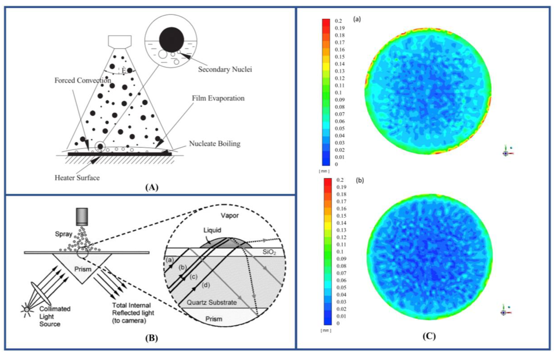
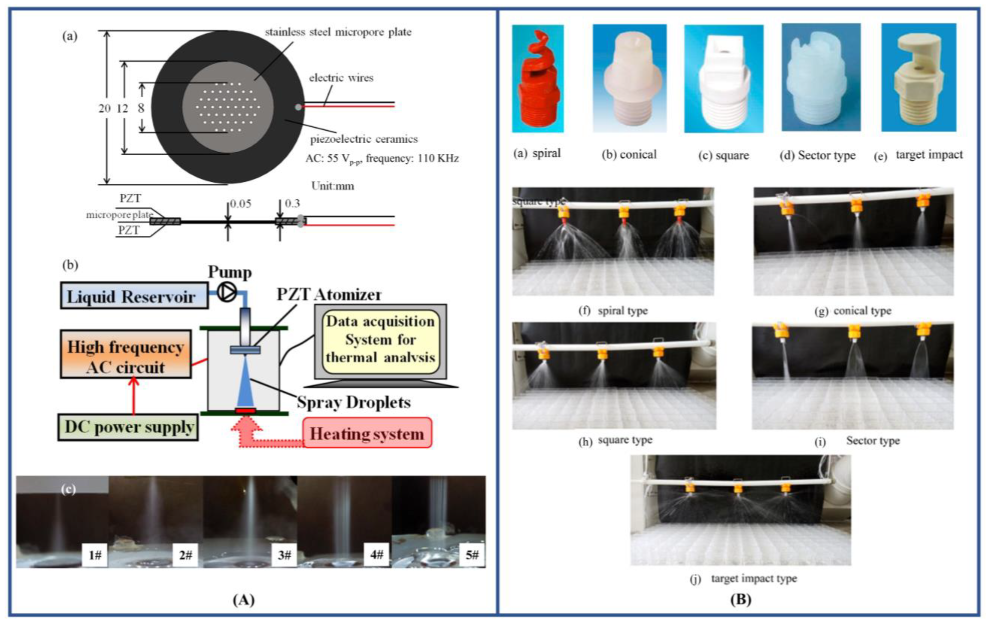
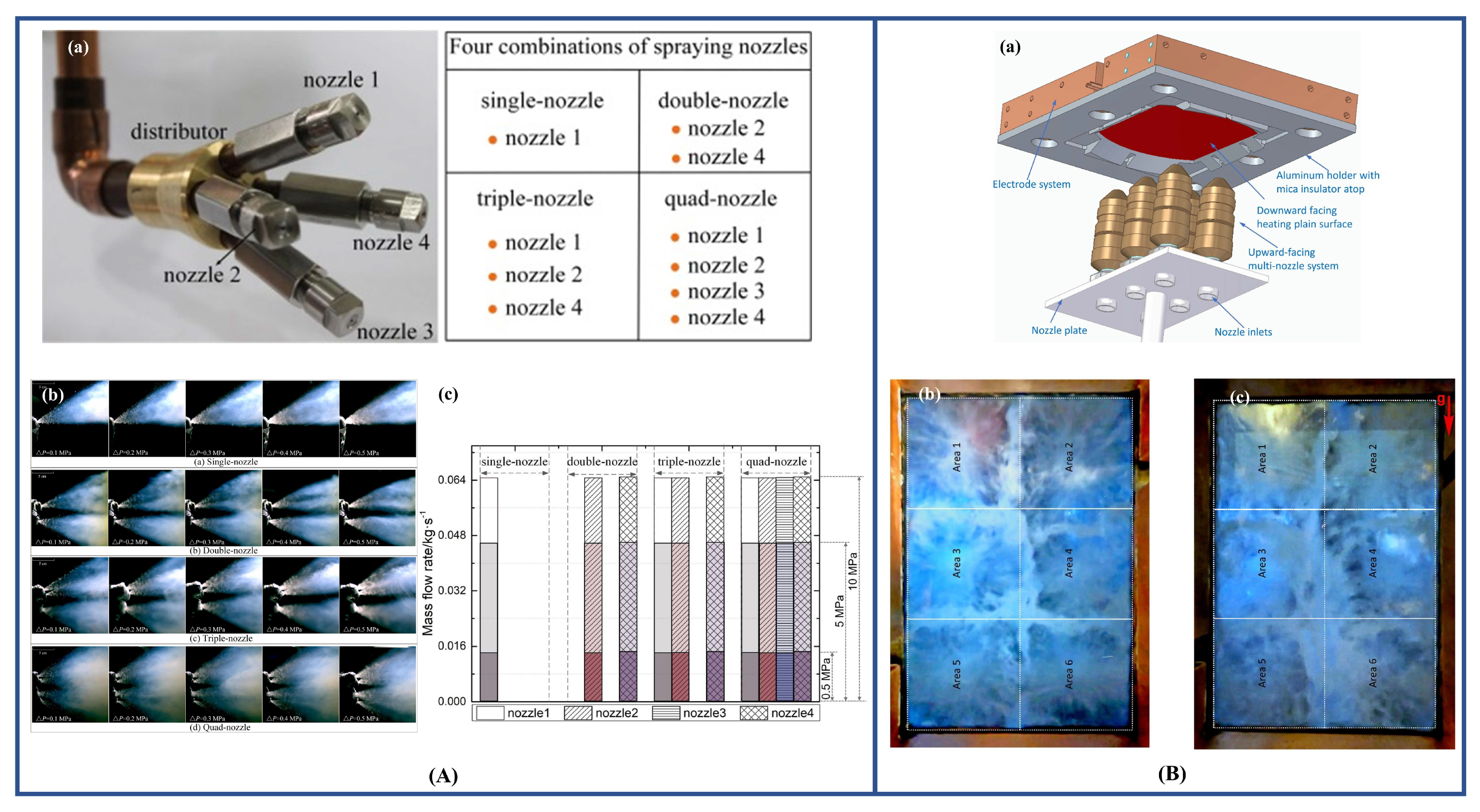
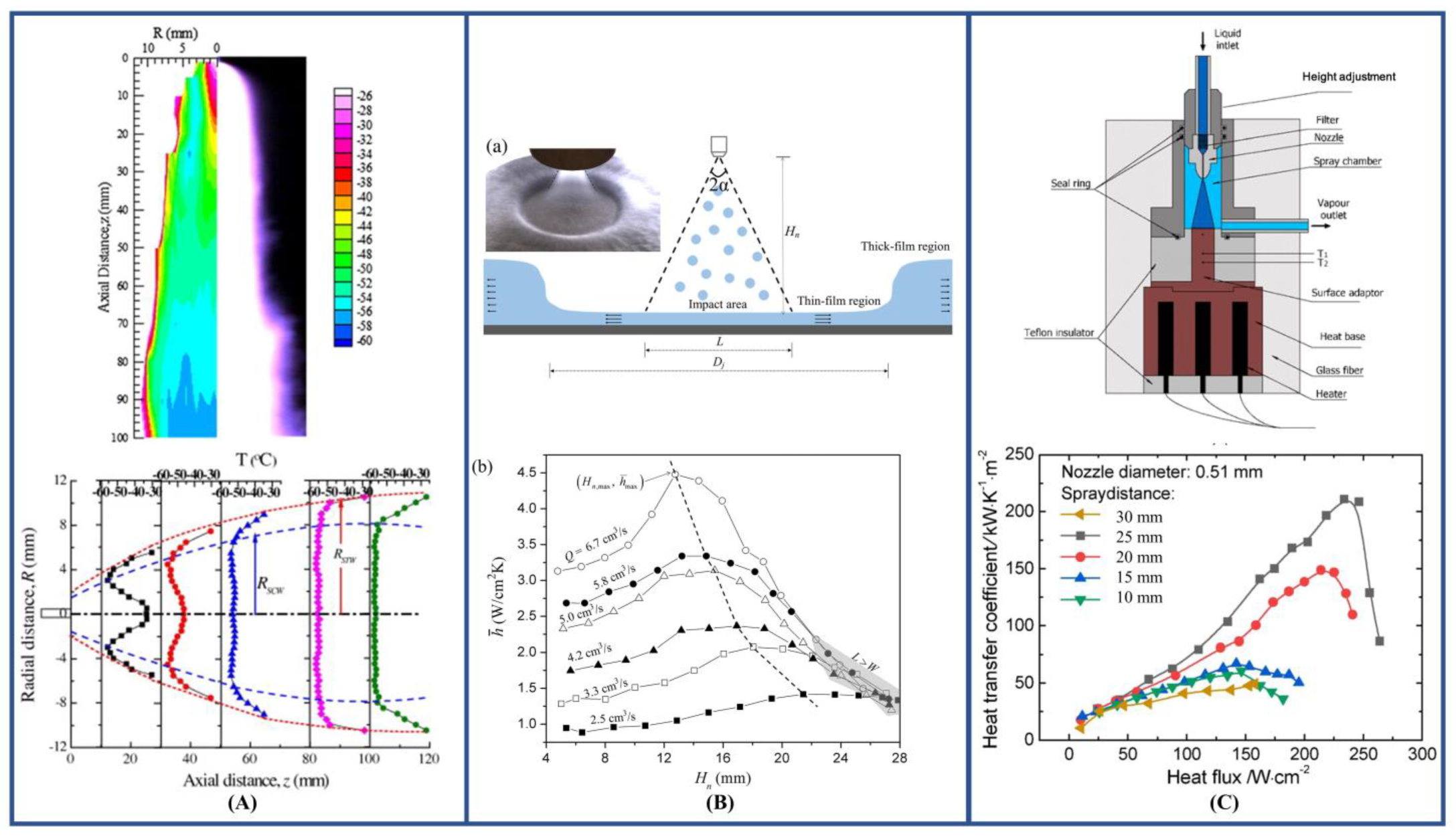
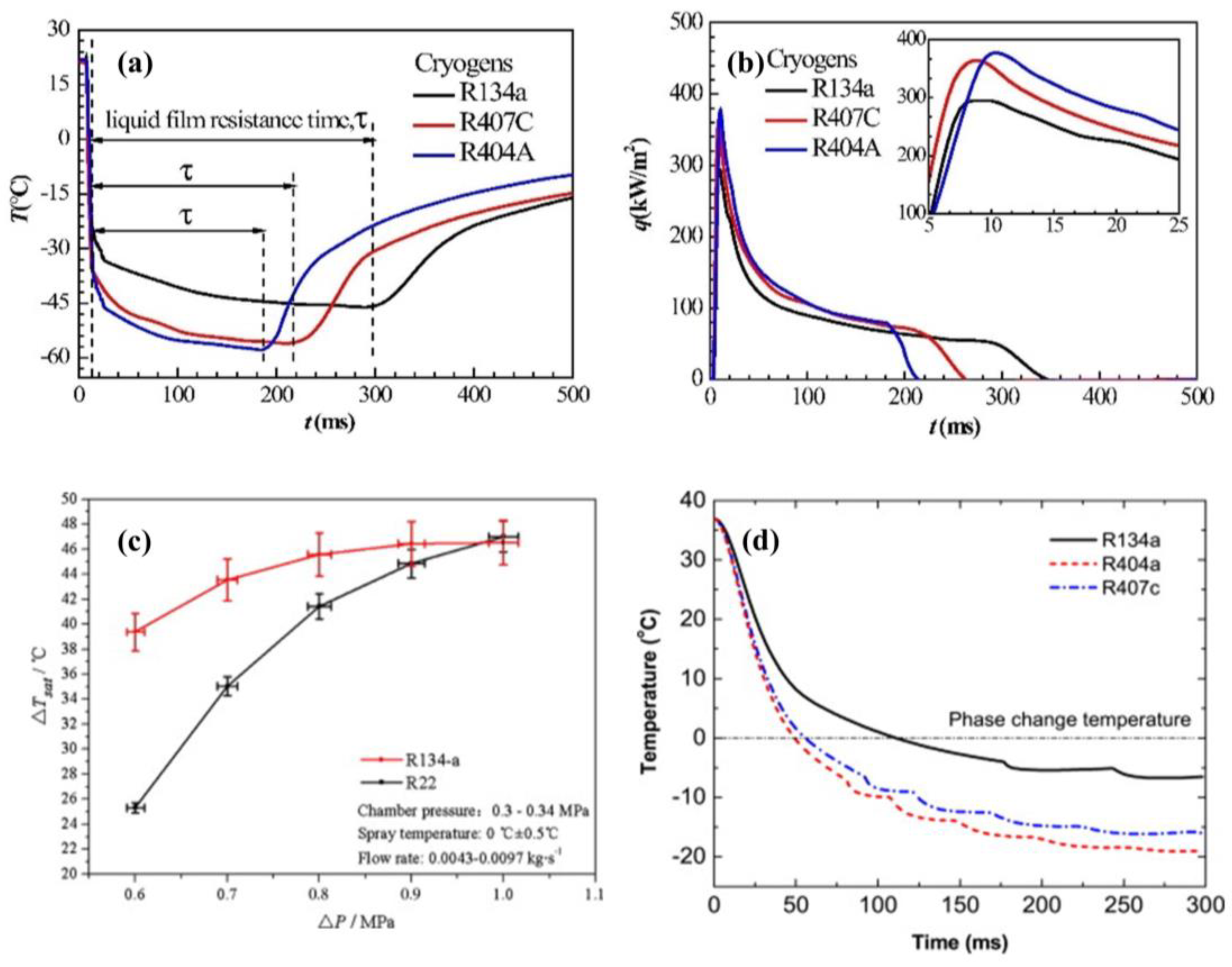
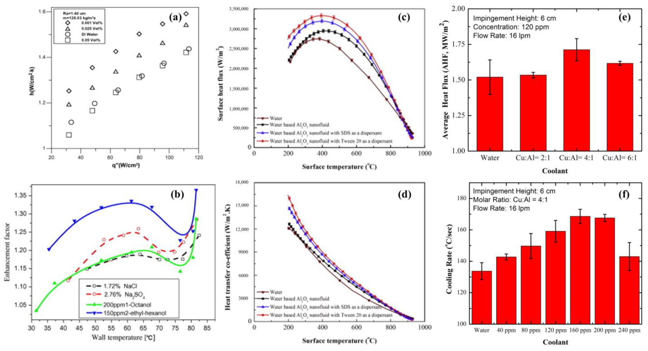
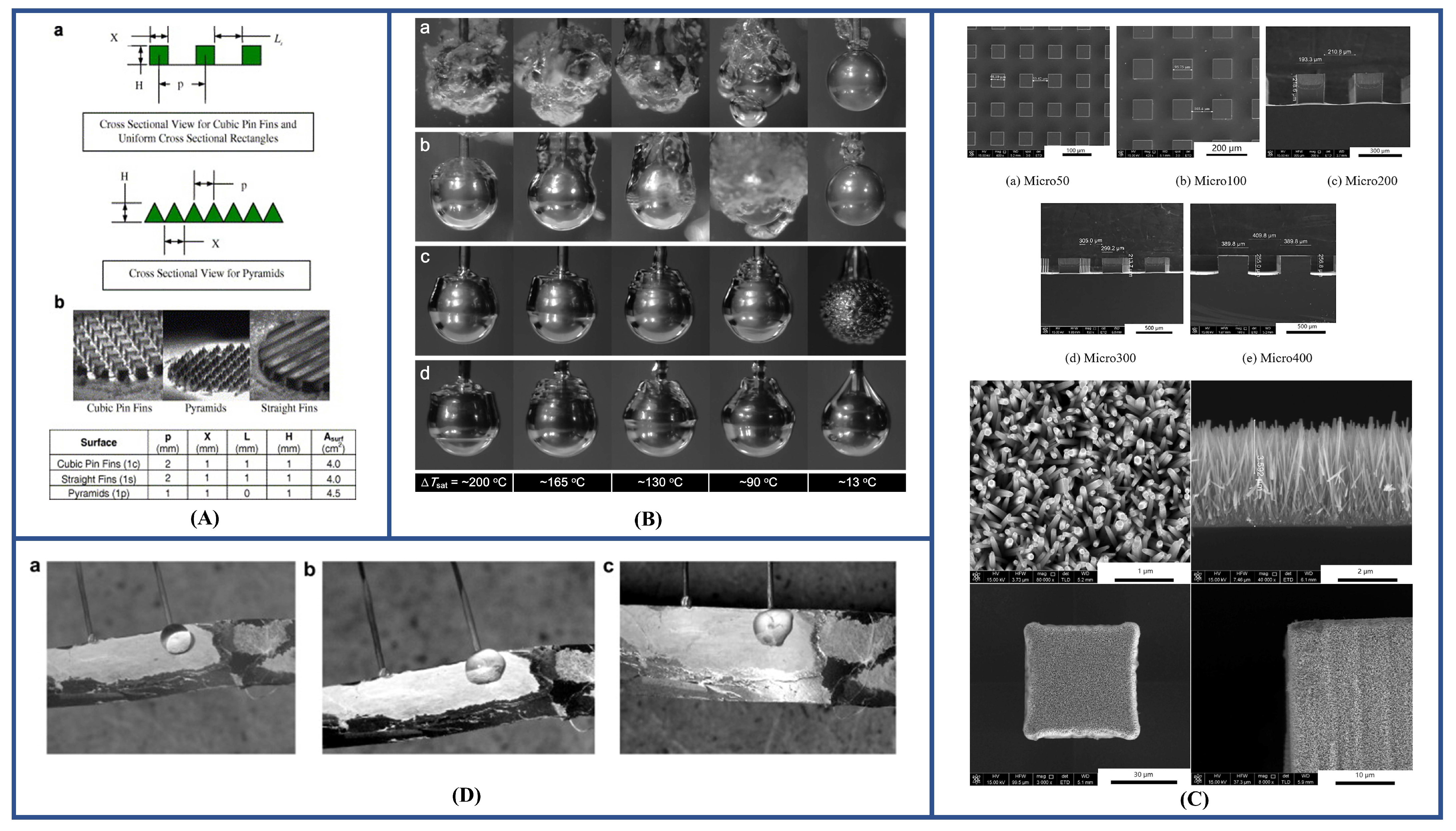
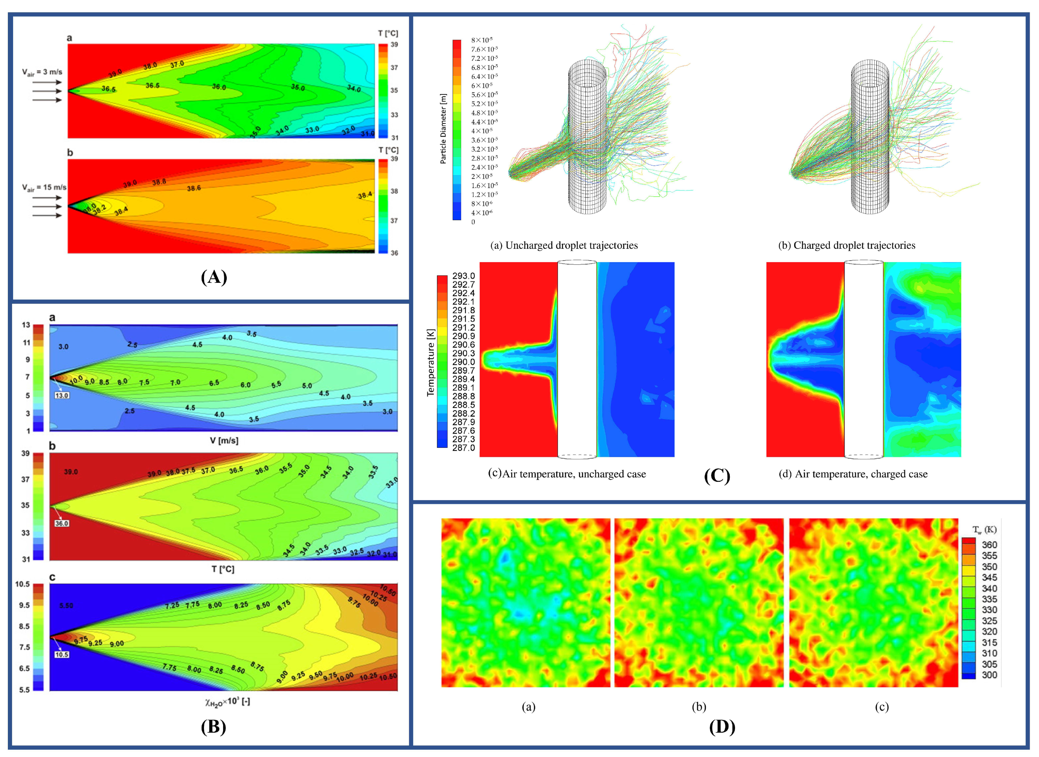
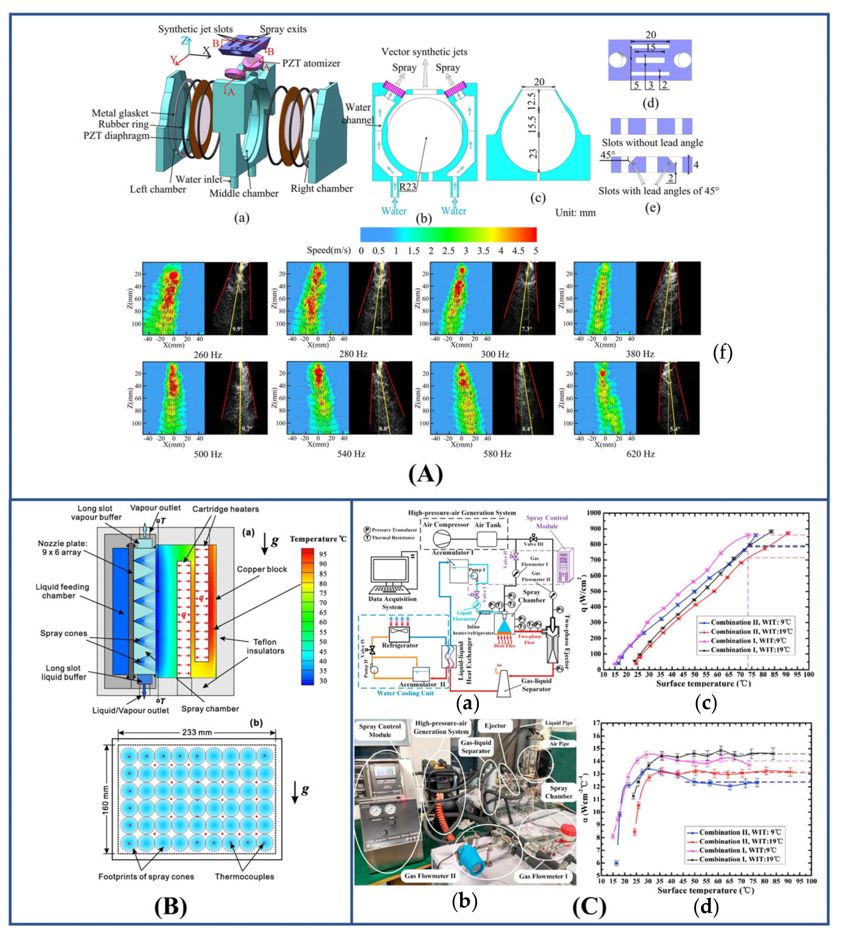
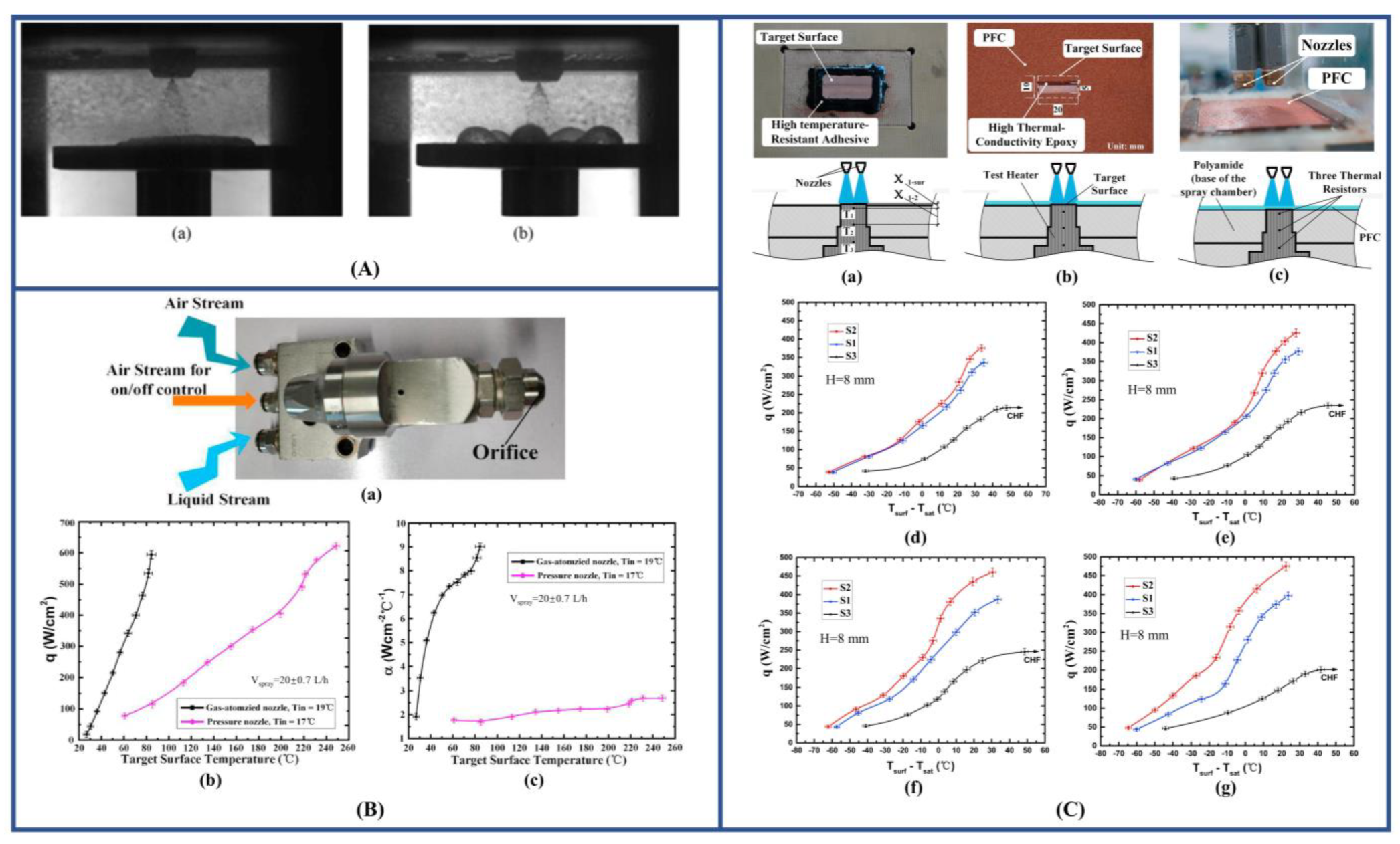
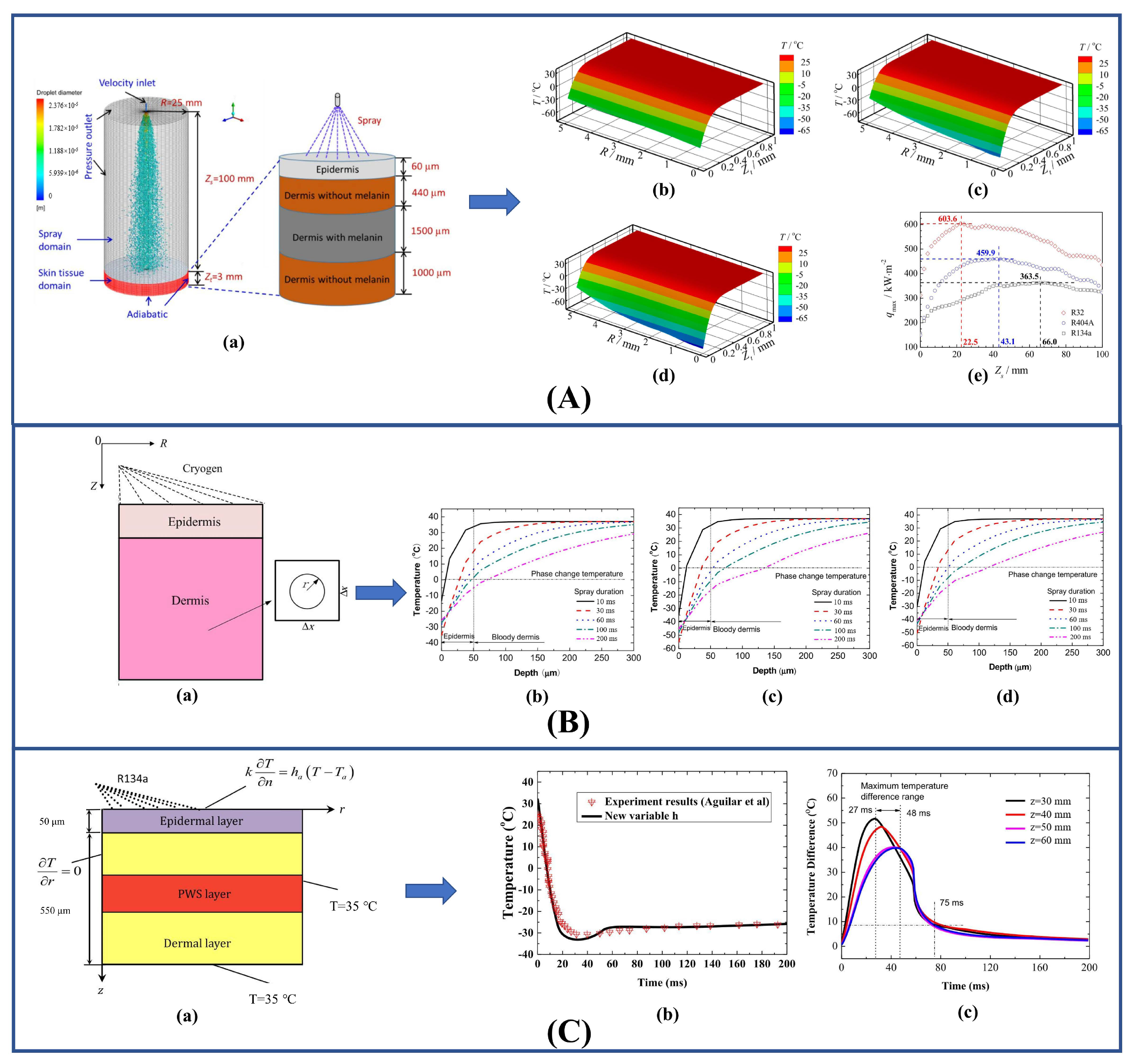
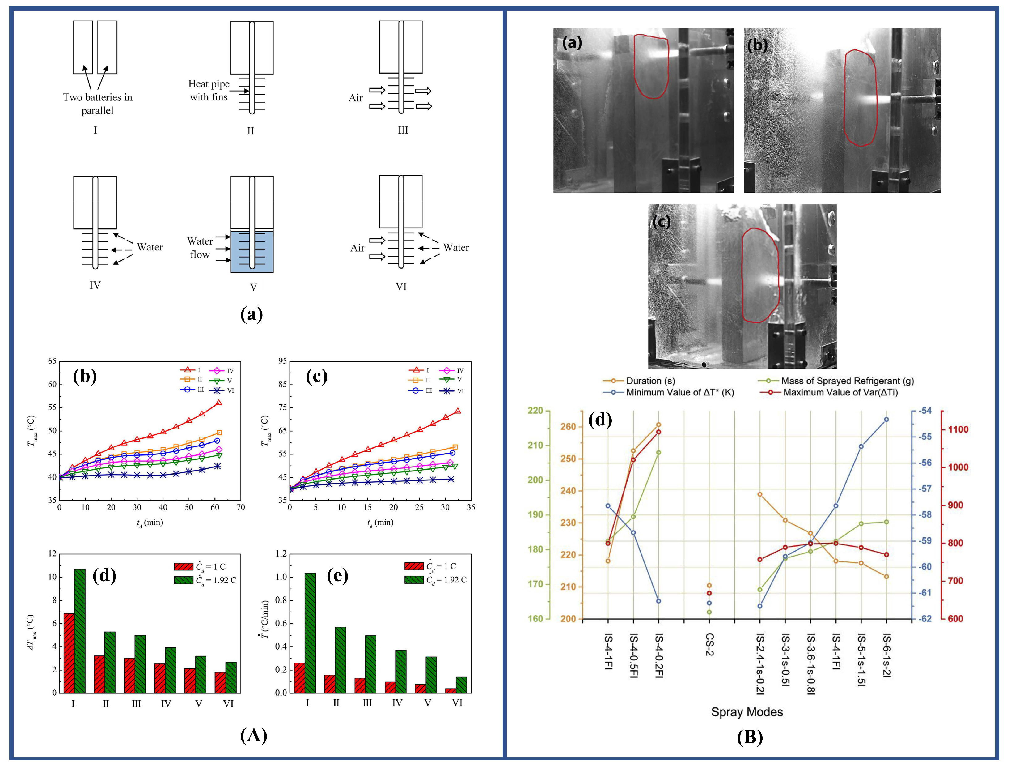
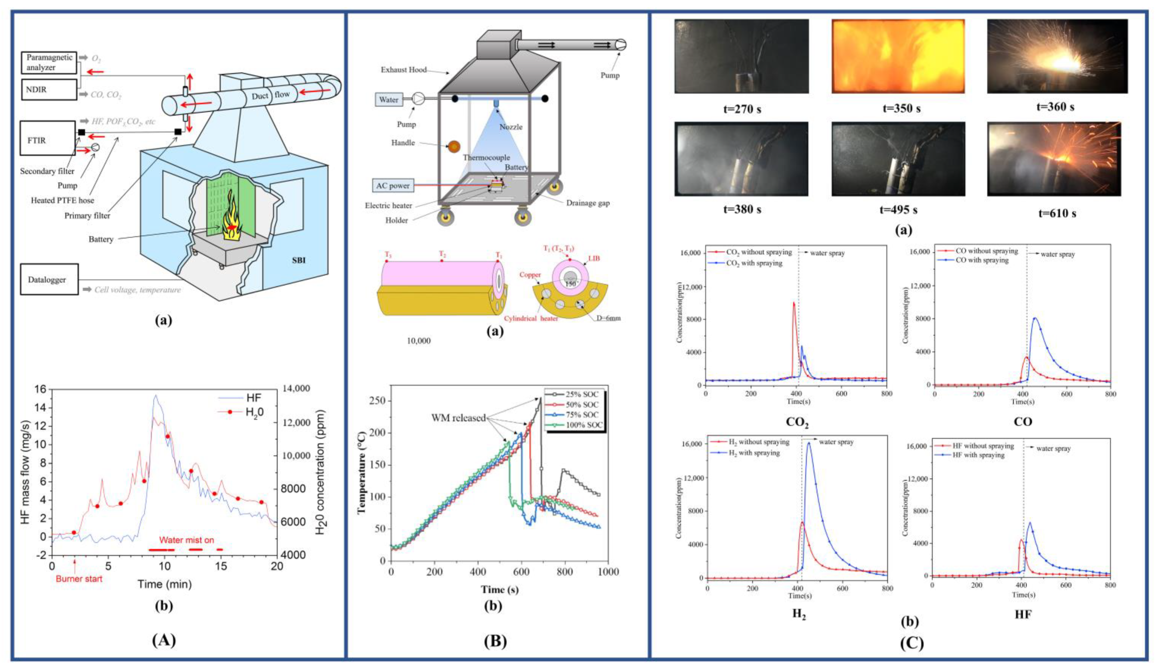
Table 1.
The relationship between average diameter and true diameter.
| Nozzle Diameter | Injection Medium | Year | Author | Remarks |
|---|---|---|---|---|
| Freon-113 | 1991 [33] | Ghodbane, Holman | θ: The spray cone angle | |
| FC-72 and water | 1995 [34] | I. Mudawar, K.A. Estes | ||
| FC-72, FC-87 | 1996 [35] | P: nozzle pressure drop; : nozzle diameter | ||
| 1999 [36] | Nasr | = 0.61–1.7 mm | ||
| Water | 2011 [37] | Cheng | R: the cross-section radius at a certain spray height. D: diameter of the heating surface D = 12 mm. | |
| HFE-7100, HFE-7300 | 2020 [38] | Hsieh | 60 ≤ ≤ 140 10 ≤ ≤ 40 | |
| 2021 [39] | Li, Zhao | : 3.2~6.5 Height of nozzle: 10~20 |
Table 2.
The empirical heat transfer correlations for spray cooling experiments.
| Characterization of Heat Transfer | Injection Medium | Year | Author | Impingement Conditions | Maximum Error | Remarks |
|---|---|---|---|---|---|---|
| Water | 1998 [16] | Oliphant | = 100–1000 | 12% | ||
| Water | 2004 [51] | Jiang, Dhir | = 1000–2000 = 1.76–6.7 | 10% | : heater area; : heater surface diameter; : liquid thermal conductivity; : liquid viscosity. | |
| Water | 2011 [52] | Tao, Huai | = 520–2600 = 2.09–7.74 | |||
| Water | 2007 [53] | Karwa | = 65–285 | 7.73% | : mass flux of water per unit area of the surface. | |
| R134A | 2007 [54] | Hsieh, Tien | = 70–85 = 28–50 | The of this formula is defined as: | ||
| Water | 2010 [55] | Wang, Liu | = 15.7–24.9 kg·s−1/m2 | 2.5% | is the ambient temperature and the length scale in is surface size. | |
| PF-5060 | 2010 [56] | Abbasi | = 0–5000 kPa | 25% | No boiling heat transfer. | |
| Water | 2011 [37] | Cheng | = 2.1–6.8 | 7% | : heating surface temperature; : working fluid inlet temperature; : saturation temperature of working fluid. | |
| FC-72 | 2012 [45] | Xie | Low pressure and low flow | 20% | C1 = 0.21, C2 = 7.5, C3 = 5 1, 2, 3 correspond to different types of nozzles. | |
| Water | 2013 [57] | Xie | 12,600 20,250 0.21.0 | 14% | is determined based on nozzle orifice conditions. | |
| Water | 2018 [58] | Wang, Li | 2363.4 ≤ ≤ 4073.9 | 1.84% | Spray height: 8 cm, PFC semi-covered flat surface, consider two phase. | |
| 2668.4 ≤ ≤ 4341.3 | 1.50% | Spray height: 8 cm. PFC fully covered flat surface onside ring two phases. | ||||
| Water | 2021 [59] | 9% | ||||
| Water | 2020 [60] | Zhao, Yin | 35 80 110.8 116.2 2.3 8.8 | 30.7% | Used to predict nucleate boiling regimes. : local spray volumetric flux. | |
| Water | 2021 [48] | Zhao, Zhang | 28.8% | Liquid properties are evaluated by average surface and liquid temperature. |
Publisher’s Note: MDPI stays neutral with regard to jurisdictional claims in published maps and institutional affiliations. |
© 2022 by the authors. Licensee MDPI, Basel, Switzerland. This article is an open access article distributed under the terms and conditions of the Creative Commons Attribution (CC BY) license (https://creativecommons.org/licenses/by/4.0/).
Share and Cite
MDPI and ACS Style
Zhang, T.; Mo, Z.; Xu, X.; Liu, X.; Chen, H.; Han, Z.; Yan, Y.; Jin, Y. Advanced Study of Spray Cooling: From Theories to Applications. Energies 2022, 15, 9219. https://doi.org/10.3390/en15239219
AMA Style
Zhang T, Mo Z, Xu X, Liu X, Chen H, Han Z, Yan Y, Jin Y. Advanced Study of Spray Cooling: From Theories to Applications. Energies. 2022; 15(23):9219. https://doi.org/10.3390/en15239219
Chicago/Turabian StyleZhang, Tianshi, Ziming Mo, Xiaoyu Xu, Xiaoyan Liu, Haopeng Chen, Zhiwu Han, Yuying Yan, and Yingai Jin. 2022. "Advanced Study of Spray Cooling: From Theories to Applications" Energies 15, no. 23: 9219. https://doi.org/10.3390/en15239219
Note that from the first issue of 2016, this journal uses article numbers instead of page numbers. See further details here.