Staudacher 300-GS
Staudacher 300-GS
Staudacher 300-GS

Create successful ePaper yourself
Turn your PDF publications into a flip-book with our unique Google optimized e-Paper software.
Construct_<strong>Staudacher</strong> 2/9/09 12:43 PM Page 144<br />
CONSTRUCTION<br />
BY GEORGE LEU || PHOTOS BY PETE HALL & GERRY YARRISH<br />
<strong>Staudacher</strong> <strong>300</strong>-<strong>GS</strong><br />
A .60-SIZE SPORT-SCALE AEROBATIC CLASSIC<br />
The red-and-white Lap Map<br />
<strong>Staudacher</strong> is a well-known<br />
aerobatic airplane. Flown by<br />
Michael Goulian at the 1993<br />
and ’94 IAC World Championships,<br />
it has always been one of my<br />
favorites.<br />
This model’s construction is the product<br />
of teamwork. Back in 2001, Model Airplane<br />
News editor Gerry Yarrish and I discussed<br />
several airplanes suitable for construction<br />
articles. We both thought that the <strong>Staudacher</strong><br />
<strong>300</strong>-<strong>GS</strong> was a natural for a comeback.<br />
I gave Gerry a 3-view drawing, and in about<br />
three weeks, he had turned them into a set<br />
of CAD plans for a .60-size model!<br />
I built the prototype and penciled in necessary<br />
changes on the plans. After a few<br />
flights, I noted other changes to tweak its<br />
flight performance. Gerry’s plans had a<br />
scale airfoil, but I thought a thicker one similar<br />
to Joe Bridi’s Kaos design would be<br />
better. Gerry adjusted the drawings and<br />
then built his “Beta” model. Gerry’s second<br />
model is featured in this article. Let’s start<br />
building.<br />
CONSTRUCTION<br />
You’ll need the fuselage to build the wing,<br />
so let’s start there. Cut out all of the parts<br />
shown on the template page. The fuselage<br />
is a basic straight-sided box that tapers from<br />
the firewall back to the tail post. The engine<br />
box slides into place through the firewall,<br />
and it ties the front formers together. To<br />
keep the fuselage straight, draw a guideline<br />
on your workbench, and then mark vertical<br />
centerlines on all the formers. Glue the top<br />
and bottom longerons to the fuselage sides;<br />
then place the formers over the guideline,<br />
and tack-glue the sides to the formers.<br />
Check the alignment, and then permanently<br />
glue formers F1, F2 and F3 into<br />
place. Lift the fuselage from the workbench,<br />
glue the wing-saddle doublers into place,<br />
pull the tail ends together and glue them<br />
together. Recheck the fuselage for straightness,<br />
and glue the crosspieces into place.<br />
144 MODELAIRPLANENEWS.COM<br />
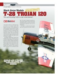
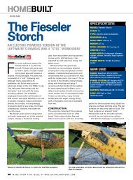
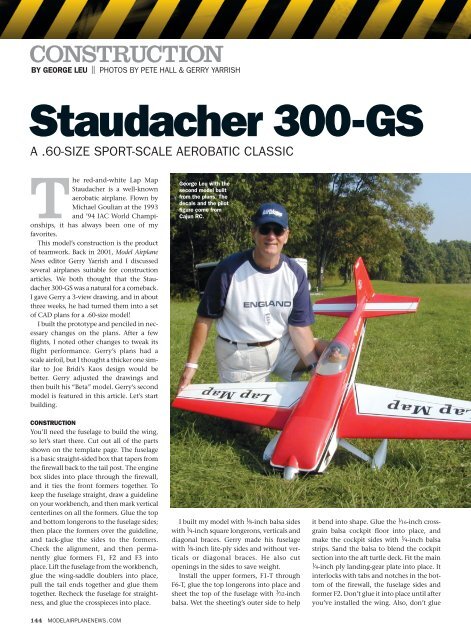
George Leu with the<br />
second model built<br />
from the plans. The<br />
decals and the pilot<br />
figure come from<br />
Cajun RC.<br />
I built my model with 1 ⁄8-inch balsa sides<br />
with 1 ⁄4-inch square longerons, verticals and<br />
diagonal braces. Gerry made his fuselage<br />
with 1 ⁄8-inch lite-ply sides and without verticals<br />
or diagonal braces. He also cut<br />
openings in the sides to save weight.<br />
Install the upper formers, F1-T through<br />
F6-T, glue the top longerons into place and<br />
sheet the top of the fuselage with 3 ⁄32-inch<br />
balsa. Wet the sheeting’s outer side to help<br />
it bend into shape. Glue the 1 ⁄16-inch crossgrain<br />
balsa cockpit floor into place, and<br />
make the cockpit sides with 1 ⁄4-inch balsa<br />
strips. Sand the balsa to blend the cockpit<br />
section into the aft turtle deck. Fit the main<br />
1 ⁄4-inch ply landing-gear plate into place. It<br />
interlocks with tabs and notches in the bottom<br />
of the firewall, the fuselage sides and<br />
former F2. Don’t glue it into place until after<br />
you’ve installed the wing. Also, don’t glue
Construct_<strong>Staudacher</strong> 2/9/09 12:43 PM Page 145<br />
SPECIFICATIONS<br />
MODEL: <strong>Staudacher</strong> <strong>300</strong>-<strong>GS</strong><br />
TYPE: sport scale aerobatic<br />
WIN<strong>GS</strong>PAN: 64.25 in.<br />
WING AREA: 695.7 sq. in.<br />
WEIGHT: 8 lb. 9 oz. (137 oz.)<br />
WING LOADING: 28.36 oz./sq. ft.<br />
LENGTH: 55 in.<br />
ENGINE REQ’D: .60 to .90 2-stroke,<br />
.91 to 1.00 4-stroke<br />
RADIO REQ’D: 4-channel (throttle,<br />
rudder, elevator, aileron)<br />
GEAR USED:<br />
ENGINE: O.S. .61FX<br />
PROP: Master Airscrew 12x7<br />
FUEL: Byron Originals 15% nitro,<br />
18% oil<br />
RADIO: JR 9303 transmitter, JR<br />
DS811 digital servos, R649 JR<br />
receiver<br />
the bottom 1 ⁄16-inch cross-grain fuselage<br />
sheeting into place until after you’ve<br />
installed all of the radio gear.<br />
The engine-box length is determined by<br />
the engine and mount you use. I used a 4stroke<br />
Saito .91 engine, and Gerry used an<br />
O.S. .61FX 2-stroke. Install the blind nuts,<br />
and glue the firewall into place with 30minute<br />
epoxy. I used Bob Smith Industries<br />
CA and 30-minute epoxy throughout.<br />
TAIL FEATHERS<br />
The tail surfaces are made out of 1 ⁄4-inch-thick<br />
balsa stock as shown on the plans. Be sure to<br />
install the balsa hinge blocks before covering.<br />
A 1 ⁄4-inch dowel joins the elevator halves.<br />
Tack-glue the horizontal stab and vertical<br />
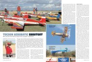
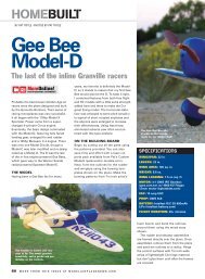
The <strong>Staudacher</strong>’s parts are easy to cut out. You can also buy laser-cut parts<br />
from Patrick Fallacaro at LasercutUSA.com.<br />
TO ORDER THE FULL-SIZE PLAN, VISIT RCSTORE.COM.<br />
THE CANOPY IS FROM A GOLDBERG<br />
STAUDACHER KIT, AND THE MAIN LANDING<br />
GEAR IS FROM A LANIER EDGE 540T ARF<br />
fin into place; then shape the fairing block<br />
out of several layers of 1 ⁄4-inch balsa sheet.<br />
Tack-glue the blocks to the aft former,<br />
remove the fin and stabilizer, install temporary<br />
1 ⁄4-inch-thick spacers in the slots,<br />
and then finish carving and sanding the<br />
blocks to blend into the fuselage. Don’t glue<br />
the tail surfaces into place until after all of<br />
the parts have been covered.<br />
WING<br />
I used an old “Adjust-O-Jig” rig to build the<br />
wing panels, but you can easily build the<br />
wing upside-down over the plans. Use balsa<br />
shims under the ribs to keep the trailing<br />
edges straight. Pin the main spar on top of<br />
the plans, and then attach the ribs to the<br />
spar. Install the bottom spar, and check the<br />
rib alignment. Tack-glue the ribs to the<br />
spars, and then add the 1 ⁄8-inch sub-leading<br />
edge sheet, and glue it to each of the ribs.<br />
Slide the aft spar into place, and then tackglue<br />
the trailing-edge sheeting to the ribs.<br />
Be sure everything remains straight and<br />
true. Bevel the aft edge of the sheeting, add<br />
the second aft spar, and glue the bottom<br />
trailing-edge sheeting into place. I installed<br />
a solid balsa trailing edge between the top<br />
and bottom sheeting, but Gerry built his<br />
wing without it. Both ways work.<br />
The tail surfaces are made of 1 ⁄4-inch-thick balsa and are built directly over the<br />
plans.<br />
JANUARY 2007 145
Construct_<strong>Staudacher</strong> 2/9/09 12:43 PM Page 146<br />
CONSTRUCTION<br />
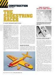
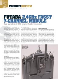
The sides of the engine box tie the firewall and formers F1 and F2 together.<br />
You can adjust the length of the box to suit the engine you choose.<br />
The servos are installed on plywood rails. Note the throttle cable and fuel-tank<br />
installation. I used hardwood dowels for the rudder and elevator pushrods.<br />
Tack-glue rib 2A into its approximate<br />
position, and leave the sub-leading-edge<br />
strip extra-long. To determine the exact<br />
placement of this half rib, you will have to<br />
attach the wing assembly to the fuselage.<br />
Repeat these steps for the second panel,<br />
and join them with the 1 ⁄8-inch dihedral<br />
braces epoxied to the front and back of the<br />
main spars. The tops of the wing panels<br />
should be flat against the building surface<br />
while the epoxy cures. Slide some balsa fill<br />
into the space between the wing ribs where<br />
the wing hold-down bolts will be installed.<br />
Center the wing in the wing saddle, and<br />
measure from each wingtip to the tail post;<br />
the sides should be the same. Trim the subleading<br />
edge sheets so that they just touch<br />
the fuselage sides; then break the half ribs<br />
free, and slide them against the fuselage<br />
sides. Slip a thin card-stock spacer between<br />
146 MODELAIRPLANENEWS.COM<br />
the ribs and the fuselage sides. Glue the ribs<br />
to the spars and the sub-leading edges.<br />
Install the center 1 ⁄8-inch plywood plate and<br />
sub-spars for the wing-alignment dowels.<br />
Before you glue the landing-gear mounting<br />
plate into place, drill through the holes in<br />
former F2 and into the plate. Remove the<br />
wing from the fuselage, and drill the holes<br />
in the plate and into the ply dihedral braces.<br />
Slide the wing-attachment dowels into<br />
place, and check their fit by placing the<br />
wing back in the saddle. The dowels should<br />
fit snugly in the holes in the former. If everything<br />
fits properly, remove the dowels, coat<br />
them with epoxy and re-insert them into<br />
the wing so that about 1 ⁄2 inch protrudes<br />
from the wing plate. Glue the leading-edge<br />
and center-section sheeting to the wing.<br />
Install the aileron servos, and cut away<br />
the aileron portions of the wing. Cap the<br />
The engine cowl is made out of balsa and foam blocks. Here, the engine determines<br />
the position of the spinner relative to the front of the cowl. See the complete<br />
“How-To” article in the July 2006 issue.<br />
I used Robart control horns and HingePoints for the elevator and rudder. The<br />
Du-Bro tailwheel is being installed. A metal strap and screw will attach it to<br />
the bottom of the rudder.<br />
aileron bays with 1 ⁄4-inch balsa, and add the<br />
leading edges and side caps to the ailerons.<br />
Bevel the leading edges, and install the<br />
aileron hinges. Install the hinge blocks<br />
inside the wing panels. Cut rib holes for the<br />
aileron-servo leads and glue the rib capstripping<br />
into place. Glue the 3 ⁄8-inch balsa<br />
leading edges to the front of the wing panels;<br />
then carve and sand them to shape.<br />
Install the hold-down blocks in the fuselage,<br />
reinstall the wing and drill through<br />
the wing for the hold-down bolts. Tap the<br />
holes in the blocks for 1 ⁄4-20 nylon bolts,<br />
and bolt the wing into place. Now build the<br />
lower wing/fuselage fairings, and glue them<br />
to the bottom of the wing.<br />
FINAL ASSEMBLY<br />
I used Robart HingePoints and did all the<br />
drilling and fitting before I covered the
Construct_<strong>Staudacher</strong> 2/9/09 12:44 PM Page 148<br />
CONSTRUCTION<br />
The aileron-servo installation and the aileron<br />
control linkage. Holes cut in the ribs allow the<br />
servo leads to pass through to the center of the<br />
wing.<br />
model in UltraCote film. The Lap Map<br />
decals are available from Cajun RC.<br />
The engine cowl is made out of balsa and<br />
foam blocks covered with fiberglass cloth<br />
and epoxy finishing resin. Cross-sections<br />
are shown on the plans. (See Gerry’s detailed<br />
how-to article in the July 2006 issue.)<br />
I used a Carl Goldberg .60-size <strong>Staudacher</strong><br />
canopy, but others are also available;<br />
Lap Map pilot — then and now!<br />
In 1992, Michael Goulian was a top-ranked U.S. aerobatics pilot and a silver medalist<br />
in the World Unlimited class. A year later, he won the Fond du Lac Cup, and in 1994,<br />
he earned a spot on the U.S. national aerobatic team flying his well-known red-andwhite<br />
“Lap Map” <strong>Staudacher</strong> <strong>300</strong>-<strong>GS</strong>. In 1995, Michael was the U.S. National<br />
Champion and went on to compete on the 1996 and 1998 teams.<br />
Michael has gone on to become one of the country’s leading high-energy aerobatics<br />
show pilots, and he regularly shares the flightline and aerobatics box with other<br />
well-known pilots such as Patty Wagstaff, Matt Chapman, Jeff Mawhinney, Sergei<br />
Boriak and Sean Tucker, to name just a few.<br />
Today, Michael flies an Extra <strong>300</strong> SHP, an upgraded version of the <strong>300</strong> S, which he<br />
debuted at the Red Bull Air race in Berlin, Germany. The series is held in cities worldwide,<br />
including Abu Dhabi (United Arab Emirates), Barcelona (Spain), Istanbul<br />
(Turkey), Perth (Australia) and San Francisco, CA. As this article goes to press, he is<br />
in fifth place overall!<br />
148 MODELAIRPLANENEWS.COM<br />
The center section of the wing is notched to fit in<br />
the wing saddle. Drill through the holes in former<br />
F2 and into this plywood plate to install the wing<br />
attachment dowels.<br />
just cut them to fit. A Cajun RC 1 ⁄5-scale<br />
pilot and a homemade instrument panel<br />
finish off the cockpit. The landing gear<br />
comes from a Lanier RC Edge 540T kit, and<br />
the wheel pants are from Stan’s FiberTech.<br />
The Du-Bro tailwheel assembly and a<br />
Tru-Turn spinner complete the hardware<br />
package. Check the model’s CG; it should<br />
be 4 1 ⁄2 inches aft of the wing’s leading edge<br />
The bottom of the wing blends into the fuselage<br />
with these built-up balsa center-section fairings.<br />
Note that the landing gear is installed in halves.<br />
measured next to the fuselage.<br />
I used hardwood dowels and threaded<br />
2-56 pushrod wires to complete the elevator<br />
and rudder control links and a Sullivan<br />
Products metal throttle cable and Du-Bro<br />
EZ Connectors for engine control.<br />
Install the receiver and battery in front of<br />
the servos, and pack foam around them.<br />
Install the fuel tanks and fuel lines, and<br />
connect them to the engine.<br />
FLYING THE “STAUD”<br />
For your first flight,take it slow and easy;<br />
set the control throws as follows:<br />
• Ailerons: ± 3 ⁄4 in. (low); ±1 in. (high)<br />
• Elevator: ± 1 ⁄2 in. (low); ± 3 ⁄4 in. (high)<br />
• Rudder: ±1 in. left and right (low); 2 in. left<br />
and right (high)<br />
• Expo: 20 to 30%<br />
Though not intended for beginners, the<br />
<strong>Staudacher</strong> is a smooth and neutrally stable<br />
flyer. Takeoffs are easy with hardly any need<br />
for rudder. It is an honest airplane and it does<br />
everything in the aerobatics book. There is<br />
very little pitch-trim change throughout the<br />
throttle range, and inverted flight requires<br />
only a touch of down-elevator. There is,<br />
however, a slight pitch coupling (toward the<br />
gear) during knife-edge flight, but this is<br />
easily dialed out with radio mixing. The<br />
wing’s thick airfoil prevents speed from<br />
building up too much, and you can easily<br />
land the model in a 3-point attitude.<br />
Whether you like fun-scale, sport aerobatics<br />
or just hot Sunday flying, the<br />
<strong>Staudacher</strong> <strong>300</strong>-<strong>GS</strong> is always a winner.<br />
Enjoy!<br />
See the Source Guide on page 166 for manufacturers’ contact information.<br />
MODELAIRPLANENEWS.COM<br />
FOR MODEL FLIGHT SHOTS,<br />
FULL-SIZE AIRCRAFT PHOTOS<br />
AND A 3-VIEW DRAWING