

F/A-18 Hornet Article - Steve's RC Homepage
F/A-18 Hornet Article - Steve's RC Homepage
F/A-18 Hornet Article - Steve's RC Homepage

Create successful ePaper yourself
Turn your PDF publications into a flip-book with our unique Google optimized e-Paper software.
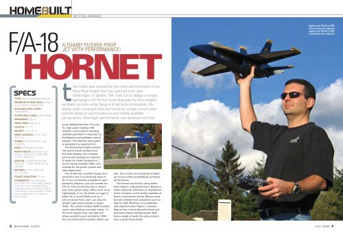
HOMEBUILT BY STEVE SHUMATE<br />
F/A-<strong>18</strong><br />
A<br />
FOAMY PUSHER-PROP<br />
JET WITH PERFORMANCE!<br />
HORNET<br />
Caption text TK this is FPO<br />
text and must be replaced<br />
Caption text TK this is FPO<br />
text and must be replaced<br />
SPECS<br />
TYPE: semi-scale pusher-prop jet<br />
MINIMUM FLYING AREA: outdoor<br />
soccer field or football field<br />
BUILDING SKILL LEVEL:<br />
intermediate<br />
FLYING SKILL LEVEL: intermediate<br />
WINGSPAN: 28.4 in.<br />
WING AREA: 254 sq. in.<br />
LENGTH: 41.7 in.<br />
WEIGHT: 15 to <strong>18</strong> oz.<br />
WING LOADING: 8.5 to 10.2<br />
oz./sq. ft.<br />
POWER: GWS EPS-350C with<br />
C gearing<br />
PROP: GWS 8x6 Slowflyer<br />
RADIO REQ’D: 6-channel microreceiver<br />
such as the GWS R6N<br />
or Hitec Electron 6<br />
SERVOS: 2 GWS Pico for the<br />
flaperons; 1 Hitec HS-55 for the<br />
stabilator<br />
BATTERY: E-Tec 1200 mAh<br />
11.1V Li-poly<br />
FLIGHT DURATION: 20 min.<br />
COMMENTS: this semiscale<br />
park flyer looks remarkably realistic<br />
in the air. It has excellent flying<br />
characteristics and is easy to fly in<br />
small fields. It also features simple,<br />
foam construction so it can be<br />
built quickly.<br />
this model was inspired by the many performances of the<br />
Navy Blue Angels that I’ve watched over Lake<br />
Washington in Seattle, WA. I set out to design a simple,<br />
lightweight F/A-<strong>18</strong> that could duplicate the Blue Angels’<br />
aerobatic routines while flying in small local schoolyards. My<br />
design goals were park-flyer performance, simple construction<br />
and the ability to use inexpensive and readily available<br />
components. Slow-flight performance was achieved with low<br />
wing loading (less than 10 oz./sq.<br />
ft.), high power loading (100<br />
watts/lb.) and excellent handling<br />
qualities (provided in large part by<br />
the flaperon and stabilator control<br />
system). The ultimate result greatly<br />
exceeded my expectations!<br />
The <strong>Hornet</strong> has simple construction<br />
and it is built entirely from<br />
thin foam sheets; only minimal<br />
carving and sanding are required.<br />
To keep the model inexpensive, I<br />
chose readily available GWS components<br />
for the power system and<br />
radio equipment.<br />
The model has excellent flying characteristics<br />
and is surprisingly easy to<br />
fly. If you can handle a standard, sport<br />
aerobatic airplane, you can handle the<br />
F/A-<strong>18</strong>. This model also has a remarkably<br />
wide speed range. When built to be<br />
lightweight, it can fly slowly enough to<br />
easily fly in small fields such as a<br />
school soccer field, yet it can also do<br />
50mph high-speed passes in larger<br />
fields. The recommended GWS brushed<br />
motor (see sidebar) provides nearly 1:1<br />
thrust to weight ratio, and that will<br />
allow excellent sport aerobatics. With<br />
the recommended brushless power system,<br />
this model can accelerate straight<br />
up and provides breathtaking aerobatic<br />
performance.<br />
The <strong>Hornet</strong> can be built using either<br />
6mm Depron or BlueCore foam. BlueCore<br />
(often called fan-fold foam) is intended for<br />
home insulation and is widely available at<br />
home-improvement stores. Depron must<br />
be mail ordered from companies such as<br />
Depron USA. BlueCore is considerably<br />
less expensive than Depron, however,<br />
Depron has a much smoother finish and<br />
produces a better-looking model. Both<br />
foams weigh virtually the same and produce<br />
a good-flying model.<br />
2 BACKYARD FLYER JULY 2005 3
HOMEBUILT<br />
CONSTRUCTION<br />
Three types of adhesives are needed to<br />
build this model. Epoxy should be used<br />
for all critical joints such as attaching the<br />
wing and installing the motor mount.<br />
Foam-safe CA or foam contact glue (such<br />
as UHU POR or UHU Creativ) can be<br />
used for the remaining foam and balsa<br />
joints (such as assembling the fuselage).<br />
3M 77 spray is necessary for tacking the<br />
paper-parts templates to the foam and<br />
for creating the laminated foam<br />
nosecone and canopy.<br />
Begin construction by cutting out all of<br />
the part templates from the plans and<br />
trim them to within roughly 1/8 inch of<br />
the outlines. Lay the templates on the<br />
foam sheet; to minimize waste, organize<br />
them so they fit as close together as possible<br />
on the sheet. After all the templates<br />
are laid out, pick up each piece, spray one<br />
side very lightly with 3M 77 spray adhesive,<br />
and then stick it back on the sheet.<br />
When you’re finished, cut out all the parts<br />
on. The nosecone and canopy are made<br />
by laminating several pieces of foam<br />
together using 3M 77 spray adhesive, and<br />
then carving and sanding them to shape.<br />
Start with coarse (100 grit) sandpaper and<br />
work your way to finer (220 grit) sandpaper.<br />
When finished, glue the nosecone to<br />
the front of the fuselage with epoxy.<br />
Now begin assembly of the aft fusethe<br />
<strong>Hornet</strong> has been a highly controversial plane ever since it<br />
was first proposed. Its detractors point at their hero—the massive<br />
F-14—and say that the <strong>Hornet</strong> isn’t worthy of following in<br />
that great airplane’s steps: no range; no load; no nothin’.<br />
Well, folks, guess what? Right or wrong, the Tomcat is on its way out,<br />
and the <strong>Hornet</strong> will soon be the only combat<br />
airplane on deck.<br />
For several reasons, the <strong>Hornet</strong> has a confusing<br />
history. For starters, as it’s known<br />
today, the <strong>Hornet</strong> is a MacDonald-Douglas<br />
airplane; only, it isn’t. It was designed and<br />
originally built by Northrup.<br />
Confusing things even more, the <strong>Hornet</strong><br />
wasn’t designed for the Navy. Furthermore, at<br />
its inception, it was a failure: known then as<br />
the XF-17, it was the loser in the U.S. Air<br />
Force’s design competition that was eventually<br />
won by the F-16 in early 1975.<br />
The same year the Northrup XF-17 lost the<br />
USAF competition, Navy brass were casting<br />
around for a less expensive, cheaper-tooperate<br />
airplane that could replace the<br />
aging Phantoms, A4s and A6s in the fleet. If<br />
you think carefully about the characteristics<br />
of the planes in that grouping, you’ll realize<br />
that the brass were biting off a mighty big<br />
chunk: they wanted one airplane to be a<br />
fighter and a specialized, tactical-attack machine. They wanted to raise<br />
aerial multitasking to a new level.<br />
Once upon a time, fighting a war meant just one thing: can we beat<br />
what the Russians are flying? That’s no longer the case. Recent wars<br />
have meant something else: can we get in, drop a lot of ordnance and, at<br />
the same time, knock down less well-trained pilots flying old Russian aircraft?<br />
Then, another factor was added to the mix: is there a way we can<br />
4 BACKYARD FLYER<br />
This is the beginning of fuselage assembly,<br />
before the nose cone has been carved to shape.<br />
Note the sheet-foam construction with balsa<br />
triangle stock at the corners.<br />
by going around the lines with a sharp X-<br />
Acto knife.<br />
FUSELAGE<br />
Begin assembly with the forward fuselage<br />
section. Glue the balsa triangle stock and<br />
bulkheads to the fuselage sides, then glue<br />
the two sides together but leave the aft<br />
end open. Glue the fuselage bottom piece<br />
F/A-<strong>18</strong> HORNET: A DYNASTY IN THE MAKING<br />
This picture shows the internal details of the<br />
fuselage. Note the laminated-foam motor-mount<br />
support with its 3/8-inch hardwood motor mount.<br />
go to war on the cheap? Where can we save a few bucks? And that’s a<br />
big part of the rationale behind the original decision to build the <strong>Hornet</strong>.<br />
The <strong>Hornet</strong> had to be a capable airplane, and in today’s world, it has<br />
more than met the Navy’s objectives. It operates at far less expense<br />
than a Tomcat; for instance, it requires something like half the number of<br />
man-hours to keep it flying.<br />
The <strong>Hornet</strong> was designed from the ground<br />
up to be a digital airplane: it’s a computer<br />
geek’s dream. Even the very early “A” models<br />
were strictly fly-by-wire planes in which the<br />
pilot flies the computer, and the computer flies<br />
the airplane.<br />
As the <strong>Hornet</strong> has evolved since its initial<br />
operational deployment in 1983 (wow; it has<br />
already been in the fleet for 22 years!), the<br />
digitalization of its flight deck has continued.<br />
The latest models have all-glass cockpits<br />
with touchscreen controls. Plus, their combat<br />
systems have been redesigned to drop fewer,<br />
but smarter, weapons. The concept is simple:<br />
don’t bomb the general area; put it through<br />
the window of the general’s bedroom.<br />
Pilots love the airplane because it’s so<br />
easy to fly, and it removes a lot of the pucker<br />
factor from landing on the boat. The larger,<br />
more powerful Super <strong>Hornet</strong>s have additional<br />
capabilities, one of which is performing as<br />
aerial tankers, and the latest F/A-<strong>18</strong>G—the “Growler”—will even<br />
replace EA-6Bs in the arena of electronic warfare.<br />
It’s just a matter of time before the only fixed-wing airplanes<br />
on a carrier are the <strong>Hornet</strong>s and the CODs. Now, if they could just modify<br />
it so it could replace those pesky helicopters ….<br />
— Budd Davisson<br />
VISIT BUDD ON THE WEB AT AIRBUM.COM.<br />
lage. Notice on the plans how the aft<br />
fuselage parts have a slight curve in<br />
them. These curves are formed by gently<br />
heating the foam with a heat gun or hair<br />
dryer and then bending them to the<br />
required shape. To judge the amount of<br />
curvature required, simply hold up each<br />
piece next to the part it will be attached<br />
to. Glue the triangle stock to the aft fuselage<br />
sides and then glue the sides to the<br />
fuselage bottom.<br />
Next, tape the free ends of the forward<br />
fuselage together and draw a centerline<br />
on the inside of both the forward and aft<br />
fuselage assemblies; then epoxy them<br />
together. Let this cure thoroughly.<br />
Laminate the two identical motor-mount<br />
supports together with 3M 77. After the<br />
glue has dried, epoxy the hardwood<br />
motor mount into place and let it cure.<br />
Check the fit of the elevator servo used<br />
and trim or shim the foam as necessary to<br />
ensure a tight fit. Epoxy the laminated<br />
motor mount onto the centerline of the aft<br />
fuselage. After the glue has cured, sand<br />
the bottom fuselage corners round. Also<br />
epoxy into place the thin-foam simulated<br />
inlet diverter at the front of the inlet.<br />
STABILATORS<br />
Install the hardware for the pivoting stabilators.<br />
The 0.157-inch-diameter carbon<br />
stabilator rod pivots inside three short<br />
pieces of 3/16-inch-diameter aluminum<br />
tube that are supported by four small<br />
squares of 1/64-inch ply glued to the fuselage<br />
sides (study the plans carefully!).<br />
Begin by gluing the plywood supports to<br />
the fuselage sides; center them over the<br />
precut holes in the foam. After the epoxy<br />
has cured, drill 3/16-inch holes through all<br />
of the plywood supports and then glue in<br />
place; make sure it is aligned with the left<br />
one. Both stabilators should be flush with<br />
the fuselage sides.<br />
Install the elevator servo. It should fit<br />
very tightly and can be held in place with<br />
tape. Make and install the 1/32-inch musicwire<br />
stabilator pushrod. After everything<br />
is centered and aligned, glue the stabilator<br />
control horn and end stop onto the carbon<br />
tube with CA.<br />
Install the motor, receiver and ESC and<br />
tape all the wires flat against the inside of<br />
the fuselage. Install and then solder on<br />
the wire extension that will connect the<br />
ESC that’s in the aft fuselage to the battery<br />
pack; use the connectors of your<br />
choice (I used Deans Ultra connectors).<br />
Make sure that the radio and motor are<br />
properly installed, and that they work corf<br />
To order the fullsize<br />
plan, turn to<br />
“<strong>RC</strong>Store.com” on<br />
page XXXXXXXXX.<br />
This shows the details of the stabilator pivot mechanism and motor<br />
installation. Note the stabilators are attached to a carbon tube that pivots<br />
inside three short pieces of aluminum tube. A drilled-out spare servo arm<br />
is used as a control horn.<br />
the aluminum-tube bearings with epoxy.<br />
Slide the carbon rod inside the bearings<br />
while the epoxy is curing to ensure proper<br />
alignment—don’t get any epoxy on the<br />
carbon rod! Make sure that the carbon rod<br />
turns freely within the bearings. After the<br />
epoxy has cured, slide the stabilator control<br />
horn and end-stop bearing onto the<br />
carbon tube, but don’t glue them yet. I<br />
used spare servo horns for both of these<br />
applications; I simply enlarged the horn’s<br />
center holes to fit the carbon tube.<br />
With fine sandpaper, round the stabilator<br />
leading edges and form a tapered contour<br />
on the trailing edge. Glue the left stabilator<br />
onto the carbon rod with 5-minute<br />
epoxy, making sure that the carbon tube<br />
is centered in the fuselage. After the glue<br />
has cured, epoxy the right stabilator in<br />
This shows the 1/32-inch plywood vertical-tail supports and the foam aftfuselage<br />
top sheeting. The foam sheeting is formed to shape by gently<br />
heating it with a heat gun or hair dryer before installation.<br />
JULY 2005 5
HOMEBUILT<br />
The removable canopy allows access to the battery compartment, and a hatch<br />
over the wing provides access to the receiver compartment. The canopy is<br />
held in place with bamboo skewers forward and small strips of Velcro ® aft.<br />
This is the completed model. It can be flown just like this; a paint job<br />
would be nice, but it isn’t required. Note how all the fuselage corners have<br />
been sanded round.<br />
rectly; after the fuselage is completed, it<br />
will be difficult to access that equipment.<br />
WING<br />
Sand the leading edge round and taper the<br />
trailing edge. Install the left and right carbon-tube<br />
wing spars with epoxy. Cover the<br />
wing with wax paper and place several<br />
heavy books on top of the pieces while the<br />
epoxy cures to ensure the wing will be<br />
perfectly flat. After the epoxy has cured,<br />
install the 1/32-inch plywood doublers on<br />
the top and bottom of the wing at the spar<br />
center section.<br />
Next, cut the flaperons from the wing.<br />
Cut a 45-degree bevel in the flaperons’<br />
leading edges using a ruler and hobby<br />
knife. I hinged the flaperons using strips of<br />
3M Satin tape on top and bottom. Draw<br />
centerlines on both the wing and fuselage,<br />
and then epoxy the wing to the top of the<br />
fuselage. Using fine sandpaper, sand the<br />
wing strakes to the cross-section shown<br />
on the plans. Glue the strakes in place with<br />
5-minute epoxy. The tabs and slots on<br />
them assure the proper alignment.<br />
VERTICAL TAILS<br />
Epoxy the aft fuselage top into place. As<br />
mentioned earlier, this piece should be<br />
preformed to the proper curvature with a<br />
heat gun before installation. Cut slots in<br />
the fuselage for the 1/32-inch-ply verticaltail<br />
supports, and then epoxy them into<br />
the fuselage. Sand the leading edges<br />
round and taper the trailing edges. Cut a<br />
20-degree bevel into the bottom of each<br />
vertical tail (be sure to make left- and<br />
right-side mirror images), and then trim<br />
the pieces to fit the aft fuselage. Cut<br />
matching slits for the plywood verticaltail<br />
supports, and then slide them onto<br />
RECOMMENDED POWER SYSTEMS<br />
» BRUSHED POWER SYSTEM<br />
MOTOR: GWS EPS-350C with “C”<br />
gearing (5.3:1)<br />
PROP: GWS 8x6 Slowflyer<br />
BATTERY: E-Tec 1200 mAh 11.1V Li-poly<br />
SPEED CONTROL: Castle Creations Pixie 20<br />
brushed controller<br />
COMMENTS: this setup provides excellent<br />
performance at minimum expense,<br />
generating 15 ounces of static thrust and a<br />
50mph top speed. The downside is that the<br />
motor won’t last long at these power settings<br />
(perhaps 3 to 5 flight hours), however, the<br />
motors are inexpensive and easy to replace.<br />
» BRUSHLESS POWER SYSTEM:<br />
MOTOR: Himaxx HA2015-4100 with “B”<br />
gearing (4.4:1)<br />
PROP: APC 9x6 Slowflyer or GWS 9x7<br />
Slowflyer<br />
BATTERY: Thunder Power 1320mAh<br />
11.1V Li-poly<br />
SPEED CONTROL: Castle Creations<br />
Phoenix 25 brushless controller<br />
COMMENTS: this setup will provide<br />
significantly more power than the brushed<br />
system and will last for years. It will produce<br />
21 ounces of static thrust with a 50mph<br />
top speed.<br />
the plywood tail supports and epoxy<br />
them in place.<br />
FINAL ASSEMBLY<br />
Install the fuselage turtle deck. First, glue<br />
the turtle-deck sides to the top of the<br />
wing; take care to approximate the curvature<br />
shown on the plans and to join the<br />
ends on the fuselage centerline. After the<br />
glue is dry, glue on the turtle-deck’s top<br />
piece and sand all the corners round. Cut<br />
an access hatch into the turtle deck above<br />
the receiver compartment to allow access<br />
to the receiver. Secure the hatch with<br />
small strips of tape.<br />
At this point, I recommend the application<br />
of a strip of 3M Satin tape around the<br />
leading edges of the wing and tail. The<br />
tape provides a smooth leading-edge and<br />
also provides more durability against the<br />
inevitable “hangar rash.”<br />
The removable canopy allows easy<br />
access to the battery compartment. It is<br />
held in place with two bamboo skewers<br />
forward (toothpicks can also be used) that<br />
slide into matching holes in the forward<br />
bulkhead and two small strips of Velcro®<br />
aft that are mounted to short pieces of<br />
1/4-inch balsa triangle stock.<br />
Install the flaperon servos and plug the<br />
servo leads into the receiver. The servo<br />
holes in the fuselage should be cut tightly<br />
enough that the servo is held in place<br />
with friction. Install the flaperon control<br />
horns and make a pushrod from 1/32-inch<br />
music wire.<br />
Test-fit the battery in the forward fuselage<br />
to determine where it should be positioned<br />
to provide the correct center of<br />
gravity (CG). The prototype model<br />
required the battery to be positioned all<br />
6 BACKYARD FLYER
HOMEBUILT<br />
This is the finished model after painting. Since the model was inspired by<br />
the Blue Angels, that was the only paint scheme that would do!<br />
Here is a close-up of the motor installation with the GWS EPS-350C geared<br />
motor. Installing a “soft-mount” prop saver is highly recommended; it will<br />
protect the prop from damage during landings.<br />
the way forward, and no other ballast was<br />
required. After the best battery location<br />
has been determined, apply a strip of<br />
Velcro® to the centerline of the fuselage<br />
and to the battery. This will allow easy<br />
adjustments of the center of gravity.<br />
PAINTING<br />
Due to the all-foam construction, painting is<br />
not required, but the model certainly looks<br />
better with a good paint job! Inexpensive<br />
acrylic paints (available at most craft stores)<br />
work well; they are inexpensive and can be<br />
sprayed or brushed on. Several brands of<br />
spray-can enamels can be used as well, but<br />
test first to ensure the paint is compatible<br />
with the foam. To keep weight to a minimum,<br />
use the foam’s natural color in your<br />
paint scheme if at all possible. Note that a<br />
full coat of lightly-sprayed acrylic paint on<br />
this model adds 0.75 ounce.<br />
FLIGHT CONTROLS<br />
This model was designed to use full-span<br />
flaperons and full-flying stabilator flight<br />
controls, driven by three microservos.<br />
Flaps help this model perform at its best,<br />
providing not only improved takeoff and<br />
landing performance but also better<br />
maneuverability. A 6-channel transmitter<br />
with flaperon mixing is required to use<br />
the flaps. Ideally, they should be set at 10<br />
degrees for launch and at 30 degrees for<br />
landing. When flying in small fields, the<br />
flaps should be set at 10 degrees throughout<br />
the flight, which will allow the model<br />
to fly slower and turn tighter. If you’re flying<br />
in a larger field and want faster<br />
speeds or better aerobatics, retract the<br />
flaps to zero after launch. For even better<br />
performance, transmitter mixing can be<br />
used to mix elevator and flaps to provide<br />
maneuverable flaps that are similar to<br />
those found on the real F/A-<strong>18</strong>. To do this,<br />
set up a mix so that full up-elevator input<br />
will drop the wing flaps’ trailing edges<br />
down about 15 degrees.<br />
If you don’t have a transmitter with flaperon<br />
mixing, this model still flies fine with<br />
ailerons only. Note that when flying in<br />
small fields, you can set up the aileron<br />
linkages to droop the ailerons 10 degrees<br />
for better slow speed performance.<br />
FLYING<br />
Before flying, make sure that the control<br />
deflections and CG location are set as specified<br />
on the plans. Use the forward-CG<br />
location for your first flights since it provides<br />
the most stability. As you gain flight<br />
experience with the model, you can move<br />
the CG aft for more maneuverability. The<br />
CG location can be easily changed by moving<br />
the battery forward or aft in the nose.<br />
Launching the model is easy. Grip the<br />
airplane near the CG, set 10 degrees flaps<br />
(optional) and 50-percent throttle, and<br />
throw it moderately hard straight ahead<br />
and parallel to the ground. Be careful to<br />
keep your hand away from the prop as<br />
you throw it! Slowly add throttle soon<br />
after launch, and after the model has<br />
gained some speed and altitude retract<br />
the flaps if desired.<br />
You’ll find this model handles very well<br />
and is capable of big graceful aerobatics<br />
just like the Blue Angels.<br />
While landings can be made without<br />
flaps, adding up to 30-degrees flaps before<br />
landing really helps slow the airplane<br />
down and allows it to float in much easier.<br />
Note that it’s very important to return the<br />
elevator to neutral just before touchdown<br />
to prevent the stabilator tips from digging<br />
into the grass! Also, be sure to pull the<br />
throttle back completely before touchdown<br />
to prevent damage to the prop. It’s a very<br />
good idea to use a “soft-mount” prop protector<br />
adapter such as the Wobbly Adapter<br />
from All E R/C to help prevent prop damage<br />
during landings.<br />
The functional wing strakes add an<br />
interesting dimension to the flying characteristics<br />
of this model. Just like on the fullsize<br />
F/A-<strong>18</strong>, they allow the airplane to fly<br />
at very high angles of attack (AoA),<br />
enabling beautiful, nose-high, flared landings<br />
and extremely tight turns and loops.<br />
Because they allow a strong lift to develop<br />
forward of the CG, the strakes create a<br />
moderate pitch-up tendency at very high<br />
AoA (30 degrees or higher) that pilots<br />
need to be aware of. This usually occurs<br />
only when flying straight and level at very<br />
low speeds and is easy to control if the<br />
pilot knows about it ahead of time. But if<br />
you’d prefer not to experience this, just<br />
don’t fly the airplane to very high AoA.<br />
This model is easy to build from<br />
scratch, but for those that have difficulty<br />
finding Depron or BlueCore foam or want<br />
to save time cutting out templates and<br />
parts, laser-cut kits are available from 3D<br />
Foamy (3dfoamy.com).<br />
Good luck; I hope you have as much<br />
fun with this model as I have. A<br />
See the Source Guide on page XX for<br />
manufacturers’ contact information.<br />
BACKYARDFLYER.COM<br />
FOR MORE<br />
CONSTRUCTION<br />
PHOTOS<br />
7 BACKYARD FLYER
