Fabric OS Encryption Administrator's Guide (KMIP), 7.1.0 - Brocade
Fabric OS Encryption Administrator's Guide (KMIP), 7.1.0 - Brocade
Fabric OS Encryption Administrator's Guide (KMIP), 7.1.0 - Brocade

You also want an ePaper? Increase the reach of your titles
YUMPU automatically turns print PDFs into web optimized ePapers that Google loves.
53-1002747-02<br />
25 March 2013<br />
®<br />
<strong>Fabric</strong> <strong>OS</strong> <strong>Encryption</strong><br />
Administrator’s <strong>Guide</strong> Supporting<br />
Key Management Interoperability Protocol<br />
(<strong>KMIP</strong>) Key-Compliant Environments<br />
Supporting <strong>Fabric</strong> <strong>OS</strong> v<strong>7.1.0</strong>
Copyright © 2012- 2013 <strong>Brocade</strong> Communications Systems, Inc. All Rights Reserved.<br />
<strong>Brocade</strong>, <strong>Brocade</strong> Assurance, the B-wing symbol, BigIron, DCX, <strong>Fabric</strong> <strong>OS</strong>, FastIron, MLX, NetIron, SAN Health, ServerIron,<br />
TurboIron, VCS, and VDX are registered trademarks, and AnyIO, <strong>Brocade</strong> One, CloudPlex, Effortless Networking, ICX, NET Health,<br />
OpenScript, and The Effortless Network are trademarks of <strong>Brocade</strong> Communications Systems, Inc., in the United States and/or in<br />
other countries. Other brands, products, or service names mentioned may be trademarks of their respective owners.<br />
Notice: This document is for informational purposes only and does not set forth any warranty, expressed or implied, concerning<br />
any equipment, equipment feature, or service offered or to be offered by <strong>Brocade</strong>. <strong>Brocade</strong> reserves the right to make changes to<br />
this document at any time, without notice, and assumes no responsibility for its use. This informational document describes<br />
features that may not be currently available. Contact a <strong>Brocade</strong> sales office for information on feature and product availability.<br />
Export of technical data contained in this document may require an export license from the United States government.<br />
The authors and <strong>Brocade</strong> Communications Systems, Inc. shall have no liability or responsibility to any person or entity with<br />
respect to any loss, cost, liability, or damages arising from the information contained in this book or the computer programs that<br />
accompany it.<br />
The product described by this document may contain “open source” software covered by the GNU General Public License or other<br />
open source license agreements. To find out which open source software is included in <strong>Brocade</strong> products, view the licensing<br />
terms applicable to the open source software, and obtain a copy of the programming source code, please visit<br />
http://www.brocade.com/support/oscd.<br />
<strong>Brocade</strong> Communications Systems, Incorporated<br />
Corporate and Latin American Headquarters<br />
<strong>Brocade</strong> Communications Systems, Inc.<br />
130 Holger Way<br />
San Jose, CA 95134<br />
Tel: 1-408-333-8000<br />
Fax: 1-408-333-8101<br />
E-mail: info@brocade.com<br />
European Headquarters<br />
<strong>Brocade</strong> Communications Switzerland Sàrl<br />
Centre Swissair<br />
Tour B - 4ème étage<br />
29, Route de l'Aéroport<br />
Case Postale 105<br />
CH-1215 Genève 15<br />
Switzerland<br />
Tel: +41 22 799 5640<br />
Fax: +41 22 799 5641<br />
E-mail: emea-info@brocade.com<br />
Asia-Pacific Headquarters<br />
<strong>Brocade</strong> Communications Systems China HK, Ltd.<br />
No. 1 Guanghua Road<br />
Chao Yang District<br />
Units 2718 and 2818<br />
Beijing 100020, China<br />
Tel: +8610 6588 8888<br />
Fax: +8610 6588 9999<br />
E-mail: china-info@brocade.com<br />
Asia-Pacific Headquarters<br />
<strong>Brocade</strong> Communications Systems Co., Ltd. (Shenzhen WFOE)<br />
Citic Plaza<br />
No. 233 Tian He Road North<br />
Unit 1308 – 13th Floor<br />
Guangzhou, China<br />
Tel: +8620 3891 2000<br />
Fax: +8620 3891 2111<br />
E-mail: china-info@brocade.com<br />
Document History<br />
Title Publication number Summary of changes Date<br />
<strong>Fabric</strong> <strong>OS</strong> Administrator’s <strong>Guide</strong> Supporting<br />
Key Management Interoperability Protocol<br />
(<strong>KMIP</strong>) Key-Compliant Environments<br />
<strong>Fabric</strong> <strong>OS</strong> Administrator’s <strong>Guide</strong> Supporting<br />
Key Management Interoperability Protocol<br />
(<strong>KMIP</strong>) Key-Compliant Environments<br />
53-1002747-02 Added HA cluster<br />
information and reviewer<br />
comments<br />
March 2013<br />
53-1002747-01 New product release December 2012
Contents<br />
About This Document<br />
In this chapter . . . . . . . . . . . . . . . . . . . . . . . . . . . . . . . . . . . . . . . . . . . xiii<br />
How this document is organized . . . . . . . . . . . . . . . . . . . . . . . . . . . . xiii<br />
Supported hardware and software . . . . . . . . . . . . . . . . . . . . . . . . . . xiv<br />
What’s new in this document. . . . . . . . . . . . . . . . . . . . . . . . . . . . . . . xiv<br />
Document conventions. . . . . . . . . . . . . . . . . . . . . . . . . . . . . . . . . . . . xiv<br />
Text formatting . . . . . . . . . . . . . . . . . . . . . . . . . . . . . . . . . . . . . . . xiv<br />
Command syntax conventions . . . . . . . . . . . . . . . . . . . . . . . . . . xv<br />
Notes, cautions, and warnings . . . . . . . . . . . . . . . . . . . . . . . . . . xv<br />
Key terms . . . . . . . . . . . . . . . . . . . . . . . . . . . . . . . . . . . . . . . . . . . xvi<br />
Additional information. . . . . . . . . . . . . . . . . . . . . . . . . . . . . . . . . . . . . xvi<br />
<strong>Brocade</strong> resources. . . . . . . . . . . . . . . . . . . . . . . . . . . . . . . . . . . . xvi<br />
Other industry resources. . . . . . . . . . . . . . . . . . . . . . . . . . . . . . . xvi<br />
Getting technical help. . . . . . . . . . . . . . . . . . . . . . . . . . . . . . . . . . . . .xvii<br />
Document feedback . . . . . . . . . . . . . . . . . . . . . . . . . . . . . . . . . . . . . xviii<br />
Chapter 1<br />
<strong>Encryption</strong> Overview<br />
In this chapter . . . . . . . . . . . . . . . . . . . . . . . . . . . . . . . . . . . . . . . . . . . 1<br />
Host and LUN considerations. . . . . . . . . . . . . . . . . . . . . . . . . . . . . . . . 1<br />
Terminology . . . . . . . . . . . . . . . . . . . . . . . . . . . . . . . . . . . . . . . . . . . . . . 2<br />
The <strong>Brocade</strong> <strong>Encryption</strong> Switch . . . . . . . . . . . . . . . . . . . . . . . . . . . . . . 4<br />
The FS8-18 blade . . . . . . . . . . . . . . . . . . . . . . . . . . . . . . . . . . . . . . . . . 5<br />
FIPS mode . . . . . . . . . . . . . . . . . . . . . . . . . . . . . . . . . . . . . . . . . . . . . . . 5<br />
Performance licensing . . . . . . . . . . . . . . . . . . . . . . . . . . . . . . . . . . . . . 5<br />
Adding a license. . . . . . . . . . . . . . . . . . . . . . . . . . . . . . . . . . . . . . . 5<br />
Licensing best practices . . . . . . . . . . . . . . . . . . . . . . . . . . . . . . . . 5<br />
Recommendation for connectivity . . . . . . . . . . . . . . . . . . . . . . . . . . . . 6<br />
Usage limitations. . . . . . . . . . . . . . . . . . . . . . . . . . . . . . . . . . . . . . . . . . 6<br />
<strong>Brocade</strong> encryption solution overview. . . . . . . . . . . . . . . . . . . . . . . . . 7<br />
Data flow from server to storage . . . . . . . . . . . . . . . . . . . . . . . . . 8<br />
Data encryption key life cycle management . . . . . . . . . . . . . . . . . . . . 9<br />
Master key management . . . . . . . . . . . . . . . . . . . . . . . . . . . . . . . . . . 11<br />
Master key generation. . . . . . . . . . . . . . . . . . . . . . . . . . . . . . . . . 11<br />
Master key backup. . . . . . . . . . . . . . . . . . . . . . . . . . . . . . . . . . . . 11<br />
<strong>Fabric</strong> <strong>OS</strong> <strong>Encryption</strong> Administrator’s <strong>Guide</strong> (<strong>KMIP</strong>)<br />
53-1002747-02<br />
iii
Support for virtual fabrics. . . . . . . . . . . . . . . . . . . . . . . . . . . . . . . . . . 11<br />
Cisco <strong>Fabric</strong> Connectivity support . . . . . . . . . . . . . . . . . . . . . . . . . . .12<br />
Chapter 2<br />
Configuring <strong>Encryption</strong> Using the Management Application<br />
In this chapter . . . . . . . . . . . . . . . . . . . . . . . . . . . . . . . . . . . . . . . . . . 13<br />
<strong>Encryption</strong> Center features. . . . . . . . . . . . . . . . . . . . . . . . . . . . . . . . . 14<br />
<strong>Encryption</strong> user privileges . . . . . . . . . . . . . . . . . . . . . . . . . . . . . . . . .15<br />
Smart card usage . . . . . . . . . . . . . . . . . . . . . . . . . . . . . . . . . . . . . . . . 16<br />
Using authentication cards with a card reader . . . . . . . . . . . . . 16<br />
Registering authentication cards from a card reader . . . . . . . . 17<br />
Registering authentication cards from the database . . . . . . . .19<br />
Deregistering an authentication card. . . . . . . . . . . . . . . . . . . . .20<br />
Setting a quorum for authentication cards . . . . . . . . . . . . . . . .20<br />
Using system cards . . . . . . . . . . . . . . . . . . . . . . . . . . . . . . . . . . . 21<br />
Enabling or disabling the system card requirement . . . . . . . . .22<br />
Registering systems card from a card reader . . . . . . . . . . . . . .22<br />
Deregistering system cards. . . . . . . . . . . . . . . . . . . . . . . . . . . . .23<br />
Using smart cards . . . . . . . . . . . . . . . . . . . . . . . . . . . . . . . . . . . .23<br />
Tracking smart cards . . . . . . . . . . . . . . . . . . . . . . . . . . . . . . . . . .23<br />
Editing smart cards . . . . . . . . . . . . . . . . . . . . . . . . . . . . . . . . . . .25<br />
Network connections . . . . . . . . . . . . . . . . . . . . . . . . . . . . . . . . . . . . .26<br />
Blade processor links . . . . . . . . . . . . . . . . . . . . . . . . . . . . . . . . . . . . . 27<br />
Configuring blade processor links . . . . . . . . . . . . . . . . . . . . . . . 27<br />
<strong>Encryption</strong> node initialization and certificate generation. . . . . . . . .28<br />
Setting encryption node initialization . . . . . . . . . . . . . . . . . . . . .28<br />
Key Management Interoperability Protocol . . . . . . . . . . . . . . . . . . . .29<br />
Steps for connecting to a <strong>KMIP</strong> appliance (SafeNet KeySecure). . .29<br />
Setting FIPS compliance . . . . . . . . . . . . . . . . . . . . . . . . . . . . . . . 31<br />
Creating a local CA. . . . . . . . . . . . . . . . . . . . . . . . . . . . . . . . . . . .32<br />
Creating a server certificate . . . . . . . . . . . . . . . . . . . . . . . . . . . .33<br />
Creating a cluster. . . . . . . . . . . . . . . . . . . . . . . . . . . . . . . . . . . . .38<br />
Configuring a <strong>Brocade</strong> group on the KeySecure appliance . . .40<br />
Registering the KeySecure <strong>Brocade</strong> group user name and<br />
password . . . . . . . . . . . . . . . . . . . . . . . . . . . . . . . . . . . . . . . . . . . 41<br />
Signing the encryption node KAC CSR on <strong>KMIP</strong> . . . . . . . . . . . .42<br />
Importing a signed KAC certificate into a switch . . . . . . . . . . . .43<br />
Backing up the certificates . . . . . . . . . . . . . . . . . . . . . . . . . . . . .44<br />
Configuring the <strong>KMIP</strong> server . . . . . . . . . . . . . . . . . . . . . . . . . . . .46<br />
Adding a node to the cluster . . . . . . . . . . . . . . . . . . . . . . . . . . . . 47<br />
<strong>Encryption</strong> preparation . . . . . . . . . . . . . . . . . . . . . . . . . . . . . . . . . . . .49<br />
Creating an encryption group. . . . . . . . . . . . . . . . . . . . . . . . . . . . . . .50<br />
Configuring key vault settings for Key Management<br />
Interoperability Protocol (<strong>KMIP</strong>) . . . . . . . . . . . . . . . . . . . . . . . . .55<br />
Understanding configuration status results. . . . . . . . . . . . . . . .60<br />
Adding a switch to an encryption group. . . . . . . . . . . . . . . . . . . . . . . 61<br />
Replacing an encryption engine in an encryption group . . . . . . . . .67<br />
iv<br />
<strong>Fabric</strong> <strong>OS</strong> <strong>Encryption</strong> Administrator’s <strong>Guide</strong> (<strong>KMIP</strong>)<br />
53-1002747-02
High availability (HA) clusters . . . . . . . . . . . . . . . . . . . . . . . . . . . . . . .68<br />
HA cluster configuration rules . . . . . . . . . . . . . . . . . . . . . . . . . .68<br />
Creating HA clusters . . . . . . . . . . . . . . . . . . . . . . . . . . . . . . . . . .69<br />
Removing engines from an HA cluster . . . . . . . . . . . . . . . . . . . .70<br />
Swapping engines in an HA cluster . . . . . . . . . . . . . . . . . . . . . .70<br />
Failback option. . . . . . . . . . . . . . . . . . . . . . . . . . . . . . . . . . . . . . . 71<br />
Invoking failback . . . . . . . . . . . . . . . . . . . . . . . . . . . . . . . . . . . . . 71<br />
Configuring encryption storage targets . . . . . . . . . . . . . . . . . . . . . . . 71<br />
Adding an encryption target . . . . . . . . . . . . . . . . . . . . . . . . . . . .72<br />
Configuring hosts for encryption targets . . . . . . . . . . . . . . . . . . . . . .80<br />
Adding target disk LUNs for encryption . . . . . . . . . . . . . . . . . . . . . . .82<br />
Configuring storage arrays . . . . . . . . . . . . . . . . . . . . . . . . . . . . . 87<br />
Adding target tape LUNs for encryption. . . . . . . . . . . . . . . . . . . . . . . 87<br />
Moving Targets . . . . . . . . . . . . . . . . . . . . . . . . . . . . . . . . . . . . . . . . . .90<br />
Configuring encrypted tape storage in a multi-path<br />
environment. . . . . . . . . . . . . . . . . . . . . . . . . . . . . . . . . . . . . . . . . . . . . 91<br />
Tape LUN write early and read ahead . . . . . . . . . . . . . . . . . . . . . . . .92<br />
Enabling and disabling tape LUN write early and<br />
read ahead . . . . . . . . . . . . . . . . . . . . . . . . . . . . . . . . . . . . . . . . . .92<br />
Tape LUN statistics . . . . . . . . . . . . . . . . . . . . . . . . . . . . . . . . . . . . . . .93<br />
Viewing and clearing tape container statistics . . . . . . . . . . . . .94<br />
Viewing and clearing tape LUN statistics for specific<br />
tape LUNs . . . . . . . . . . . . . . . . . . . . . . . . . . . . . . . . . . . . . . . . . . .95<br />
Viewing and clearing statistics for tape LUNs in a<br />
container . . . . . . . . . . . . . . . . . . . . . . . . . . . . . . . . . . . . . . . . . . . 97<br />
<strong>Encryption</strong> engine rebalancing. . . . . . . . . . . . . . . . . . . . . . . . . . . . . .98<br />
Rebalancing an encryption engine . . . . . . . . . . . . . . . . . . . . . . .99<br />
Master keys . . . . . . . . . . . . . . . . . . . . . . . . . . . . . . . . . . . . . . . . . . . . .99<br />
Active master key . . . . . . . . . . . . . . . . . . . . . . . . . . . . . . . . . . . .100<br />
Alternate master key . . . . . . . . . . . . . . . . . . . . . . . . . . . . . . . . .100<br />
Master key actions. . . . . . . . . . . . . . . . . . . . . . . . . . . . . . . . . . .100<br />
Saving the master key to a file . . . . . . . . . . . . . . . . . . . . . . . . .101<br />
Saving a master key to a key vault . . . . . . . . . . . . . . . . . . . . . .102<br />
Saving a master key to a smart card set . . . . . . . . . . . . . . . . .103<br />
Restoring a master key from a file . . . . . . . . . . . . . . . . . . . . . .105<br />
Restoring a master key from a key vault . . . . . . . . . . . . . . . . .106<br />
Restoring a master key from a smart card set. . . . . . . . . . . . .107<br />
Creating a master key . . . . . . . . . . . . . . . . . . . . . . . . . . . . . . . .108<br />
Security Settings . . . . . . . . . . . . . . . . . . . . . . . . . . . . . . . . . . . . . . . .109<br />
Zeroizing an encryption engine . . . . . . . . . . . . . . . . . . . . . . . . . . . .109<br />
Setting zeroization . . . . . . . . . . . . . . . . . . . . . . . . . . . . . . . . . . .110<br />
Using the <strong>Encryption</strong> Targets dialog box . . . . . . . . . . . . . . . . . . . . .111<br />
Redirection zones . . . . . . . . . . . . . . . . . . . . . . . . . . . . . . . . . . . . . . .112<br />
<strong>Fabric</strong> <strong>OS</strong> <strong>Encryption</strong> Administrator’s <strong>Guide</strong> (<strong>KMIP</strong>)<br />
53-1002747-02<br />
v
Disk device decommissioning . . . . . . . . . . . . . . . . . . . . . . . . . . . . .112<br />
Decommissioning disk LUNs. . . . . . . . . . . . . . . . . . . . . . . . . . .113<br />
Displaying and deleting decommissioned key IDs. . . . . . . . . .113<br />
Displaying Universal IDs . . . . . . . . . . . . . . . . . . . . . . . . . . . . . .115<br />
Rekeying all disk LUNs manually . . . . . . . . . . . . . . . . . . . . . . . . . . .115<br />
Setting disk LUN Re-key All . . . . . . . . . . . . . . . . . . . . . . . . . . . .116<br />
Viewing disk LUN rekeying details . . . . . . . . . . . . . . . . . . . . . .117<br />
Viewing the progress of manual rekey operations. . . . . . . . . .119<br />
Thin provisioned LUNs . . . . . . . . . . . . . . . . . . . . . . . . . . . . . . . . . . .120<br />
Thin provisioning support . . . . . . . . . . . . . . . . . . . . . . . . . . . . .121<br />
Viewing time left for auto rekey . . . . . . . . . . . . . . . . . . . . . . . . . . . .121<br />
Viewing and editing switch encryption properties . . . . . . . . . . . . .122<br />
Exporting the public key certificate signing request<br />
(CSR) from properties . . . . . . . . . . . . . . . . . . . . . . . . . . . . . . . .125<br />
Importing a signed public key certificate from properties . . .125<br />
Enabling and disabling the encryption engine state from<br />
properties . . . . . . . . . . . . . . . . . . . . . . . . . . . . . . . . . . . . . . . . . .126<br />
Viewing and editing encryption group properties . . . . . . . . . . . . . .126<br />
General tab. . . . . . . . . . . . . . . . . . . . . . . . . . . . . . . . . . . . . . . . .128<br />
Members tab . . . . . . . . . . . . . . . . . . . . . . . . . . . . . . . . . . . . . . .130<br />
Consequences of removing an encryption switch . . . . . . . . . .132<br />
Security tab . . . . . . . . . . . . . . . . . . . . . . . . . . . . . . . . . . . . . . . .133<br />
HA Clusters tab. . . . . . . . . . . . . . . . . . . . . . . . . . . . . . . . . . . . . .135<br />
Tape Pools tab . . . . . . . . . . . . . . . . . . . . . . . . . . . . . . . . . . . . . .137<br />
Engine Operations tab . . . . . . . . . . . . . . . . . . . . . . . . . . . . . . . .139<br />
<strong>Encryption</strong>-related acronyms in log messages . . . . . . . . . . . . . . . .140<br />
Chapter 3<br />
Configuring <strong>Encryption</strong> Using the CLI<br />
In this chapter . . . . . . . . . . . . . . . . . . . . . . . . . . . . . . . . . . . . . . . . . 141<br />
Overview . . . . . . . . . . . . . . . . . . . . . . . . . . . . . . . . . . . . . . . . . . . . . .142<br />
Command validation checks . . . . . . . . . . . . . . . . . . . . . . . . . . . . . .142<br />
Command RBAC permissions and AD types . . . . . . . . . . . . . . . . . .143<br />
Cryptocfg Help command output . . . . . . . . . . . . . . . . . . . . . . . . . . .145<br />
Management LAN configuration . . . . . . . . . . . . . . . . . . . . . . . . . . .146<br />
Configuring cluster links . . . . . . . . . . . . . . . . . . . . . . . . . . . . . . . . . .146<br />
Special consideration for blades . . . . . . . . . . . . . . . . . . . . . . .147<br />
IP Address change of a node within an encryption group. . . .148<br />
Setting encryption node initialization . . . . . . . . . . . . . . . . . . . . . . .148<br />
vi<br />
<strong>Fabric</strong> <strong>OS</strong> <strong>Encryption</strong> Administrator’s <strong>Guide</strong> (<strong>KMIP</strong>)<br />
53-1002747-02
Steps for connecting to a <strong>KMIP</strong> appliance<br />
(SafeNet KeySecure). . . . . . . . . . . . . . . . . . . . . . . . . . . . . . . . . . . . .149<br />
Setting FIPS compliance . . . . . . . . . . . . . . . . . . . . . . . . . . . . . .150<br />
Creating a local CA. . . . . . . . . . . . . . . . . . . . . . . . . . . . . . . . . . .150<br />
Creating a server certificate . . . . . . . . . . . . . . . . . . . . . . . . . . .150<br />
Creating a cluster. . . . . . . . . . . . . . . . . . . . . . . . . . . . . . . . . . . .150<br />
Backing up the certificates . . . . . . . . . . . . . . . . . . . . . . . . . . . .151<br />
Configuring the <strong>KMIP</strong> server . . . . . . . . . . . . . . . . . . . . . . . . . . .151<br />
Adding a node to the cluster . . . . . . . . . . . . . . . . . . . . . . . . . . .151<br />
Configuring the <strong>Brocade</strong> <strong>Encryption</strong> Switch key vault setup<br />
(SafeNet KeySecure). . . . . . . . . . . . . . . . . . . . . . . . . . . . . . . . . . . . .152<br />
Setting the key vault type to <strong>KMIP</strong> . . . . . . . . . . . . . . . . . . . . . .152<br />
Setting key vault Parameters . . . . . . . . . . . . . . . . . . . . . . . . . .152<br />
Exporting the KAC CSR to a local machine . . . . . . . . . . . . . . .152<br />
Signing the KAC CSR using the Local CA . . . . . . . . . . . . . . . . .153<br />
Configure the user name and password . . . . . . . . . . . . . . . . .154<br />
Register the KAC certificate . . . . . . . . . . . . . . . . . . . . . . . . . . .156<br />
Register the key vaults as primary and secondary<br />
key vaults . . . . . . . . . . . . . . . . . . . . . . . . . . . . . . . . . . . . . . . . . .156<br />
Verify connectivity . . . . . . . . . . . . . . . . . . . . . . . . . . . . . . . . . . .156<br />
Initializing the <strong>Brocade</strong> encryption engines . . . . . . . . . . . . . . .157<br />
Registering <strong>KMIP</strong> on a <strong>Brocade</strong> encryption group leader . . . .158<br />
Adding a member node to an encryption group . . . . . . . . . . . . . . .160<br />
Generating and backing up the master key . . . . . . . . . . . . . . . . . .163<br />
High availability clusters . . . . . . . . . . . . . . . . . . . . . . . . . . . . . . . . . .164<br />
HA cluster configuration rules. . . . . . . . . . . . . . . . . . . . . . . . . .164<br />
Creating an HA cluster. . . . . . . . . . . . . . . . . . . . . . . . . . . . . . . .165<br />
Adding an encryption engine to an HA cluster. . . . . . . . . . . . .166<br />
Removing engines from an HA cluster . . . . . . . . . . . . . . . . . . .166<br />
Swapping engines in an HA cluster . . . . . . . . . . . . . . . . . . . . .166<br />
Failover/failback policy configuration. . . . . . . . . . . . . . . . . . . .167<br />
Re-exporting a master key . . . . . . . . . . . . . . . . . . . . . . . . . . . . . . . .169<br />
Exporting an additional key ID . . . . . . . . . . . . . . . . . . . . . . . . .170<br />
Viewing the master key IDs . . . . . . . . . . . . . . . . . . . . . . . . . . . .170<br />
Enabling the encryption engine . . . . . . . . . . . . . . . . . . . . . . . . . . . .172<br />
Checking encryption engine status . . . . . . . . . . . . . . . . . . . . .172<br />
Zoning considerations . . . . . . . . . . . . . . . . . . . . . . . . . . . . . . . . . . .173<br />
Setting default zoning to no access . . . . . . . . . . . . . . . . . . . . .173<br />
Frame redirection zoning. . . . . . . . . . . . . . . . . . . . . . . . . . . . . . 174<br />
Creating an initiator - target zone . . . . . . . . . . . . . . . . . . . . . . . 174<br />
CryptoTarget container configuration . . . . . . . . . . . . . . . . . . . . . . . 176<br />
LUN rebalancing when hosting both disk and tape targets . .177<br />
Gathering information . . . . . . . . . . . . . . . . . . . . . . . . . . . . . . . .178<br />
Creating a CryptoTarget container . . . . . . . . . . . . . . . . . . . . . .178<br />
Removing an initiator from a CryptoTarget container . . . . . . .180<br />
Deleting a CryptoTarget container . . . . . . . . . . . . . . . . . . . . . .181<br />
Moving a CryptoTarget container . . . . . . . . . . . . . . . . . . . . . . .181<br />
<strong>Fabric</strong> <strong>OS</strong> <strong>Encryption</strong> Administrator’s <strong>Guide</strong> (<strong>KMIP</strong>)<br />
53-1002747-02<br />
vii
Crypto LUN configuration . . . . . . . . . . . . . . . . . . . . . . . . . . . . . . . . .182<br />
Discovering a LUN . . . . . . . . . . . . . . . . . . . . . . . . . . . . . . . . . . .183<br />
Configuring a Crypto LUN . . . . . . . . . . . . . . . . . . . . . . . . . . . . .183<br />
Crypto LUN parameters and policies . . . . . . . . . . . . . . . . . . . .185<br />
Configuring a tape LUN . . . . . . . . . . . . . . . . . . . . . . . . . . . . . . .187<br />
Removing a LUN from a CryptoTarget container . . . . . . . . . . .188<br />
Modifying Crypto LUN parameters . . . . . . . . . . . . . . . . . . . . . .189<br />
LUN modification considerations . . . . . . . . . . . . . . . . . . . . . . .190<br />
Impact of tape LUN configuration changes. . . . . . . . . . . . . . . . . . .191<br />
Configuring a multi-path Crypto LUN . . . . . . . . . . . . . . . . . . . . . . . .191<br />
Multi-path LUN configuration example. . . . . . . . . . . . . . . . . . .192<br />
Decommissioning LUNs . . . . . . . . . . . . . . . . . . . . . . . . . . . . . . . . . .195<br />
Decommissioning replicated LUNs . . . . . . . . . . . . . . . . . . . . . . . . .197<br />
Decommissioning primary LUNs only . . . . . . . . . . . . . . . . . . . .197<br />
Decommissioning secondary LUNs only . . . . . . . . . . . . . . . . .197<br />
Decommissioning primary and secondary LUN pairs . . . . . . .198<br />
Force-enabling a decommissioned disk LUN for encryption . . . . .198<br />
Force-enabling a disabled disk LUN for encryption . . . . . . . . . . . .199<br />
Tape pool configuration . . . . . . . . . . . . . . . . . . . . . . . . . . . . . . . . . .200<br />
Tape pool labeling . . . . . . . . . . . . . . . . . . . . . . . . . . . . . . . . . . .200<br />
Creating a tape pool . . . . . . . . . . . . . . . . . . . . . . . . . . . . . . . . .202<br />
Deleting a tape pool. . . . . . . . . . . . . . . . . . . . . . . . . . . . . . . . . .203<br />
Modifying a tape pool . . . . . . . . . . . . . . . . . . . . . . . . . . . . . . . .203<br />
Impact of tape pool configuration changes . . . . . . . . . . . . . . .203<br />
First-time encryption . . . . . . . . . . . . . . . . . . . . . . . . . . . . . . . . . . . . .204<br />
Resource allocation . . . . . . . . . . . . . . . . . . . . . . . . . . . . . . . . . .204<br />
First-time encryption modes . . . . . . . . . . . . . . . . . . . . . . . . . . .204<br />
Configuring a LUN for first-time encryption . . . . . . . . . . . . . . .204<br />
Thin provisioned LUNs . . . . . . . . . . . . . . . . . . . . . . . . . . . . . . . . . . .205<br />
Space reclamation. . . . . . . . . . . . . . . . . . . . . . . . . . . . . . . . . . .206<br />
Data rekeying. . . . . . . . . . . . . . . . . . . . . . . . . . . . . . . . . . . . . . . . . . .207<br />
Resource allocation . . . . . . . . . . . . . . . . . . . . . . . . . . . . . . . . . .207<br />
Rekeying modes. . . . . . . . . . . . . . . . . . . . . . . . . . . . . . . . . . . . .207<br />
Configuring a LUN for automatic rekeying . . . . . . . . . . . . . . . .208<br />
Initiating a manual rekey session . . . . . . . . . . . . . . . . . . . . . . .209<br />
Suspension and resumption of rekeying operations. . . . . . . .210<br />
Chapter 4<br />
Deployment Scenarios<br />
In this chapter . . . . . . . . . . . . . . . . . . . . . . . . . . . . . . . . . . . . . . . . . 211<br />
Single encryption switch, two paths from host to target . . . . . . . .212<br />
Single fabric deployment - HA cluster . . . . . . . . . . . . . . . . . . . . . . .213<br />
Single fabric deployment - DEK cluster . . . . . . . . . . . . . . . . . . . . . .214<br />
Dual fabric deployment - HA and DEK cluster. . . . . . . . . . . . . . . . .215<br />
Multiple paths, one DEK cluster, and two HA clusters . . . . . . . . . .216<br />
Multiple paths, DEK cluster, no HA cluster . . . . . . . . . . . . . . . . . . .218<br />
viii<br />
<strong>Fabric</strong> <strong>OS</strong> <strong>Encryption</strong> Administrator’s <strong>Guide</strong> (<strong>KMIP</strong>)<br />
53-1002747-02
Deployment in Fibre Channel routed fabrics. . . . . . . . . . . . . . . . . .220<br />
Deployment as part of an edge fabric . . . . . . . . . . . . . . . . . . . . . . .222<br />
Deployment with FCIP extension switches . . . . . . . . . . . . . . . . . . .223<br />
VMware ESX server deployments. . . . . . . . . . . . . . . . . . . . . . . . . . .224<br />
Chapter 5<br />
Best Practices and Special Topics<br />
In this chapter . . . . . . . . . . . . . . . . . . . . . . . . . . . . . . . . . . . . . . . . . 227<br />
Firmware upgrade and downgrade considerations . . . . . . . . . . . .228<br />
General guidelines. . . . . . . . . . . . . . . . . . . . . . . . . . . . . . . . . . .228<br />
Specific guidelines for HA clusters . . . . . . . . . . . . . . . . . . . . . .229<br />
Configuration upload and download considerations . . . . . . . . . . .230<br />
Configuration upload at an encryption group leader node . . .230<br />
Configuration upload at an encryption group member<br />
node . . . . . . . . . . . . . . . . . . . . . . . . . . . . . . . . . . . . . . . . . . . . . .230<br />
Information not included in an upload . . . . . . . . . . . . . . . . . . .230<br />
Steps before configuration download. . . . . . . . . . . . . . . . . . . .231<br />
Configuration download at the encryption group leader. . . . .231<br />
Configuration download at an encryption group member . . .231<br />
Steps after configuration download . . . . . . . . . . . . . . . . . . . . .232<br />
HP-UX considerations . . . . . . . . . . . . . . . . . . . . . . . . . . . . . . . . . . . .232<br />
AIX Considerations . . . . . . . . . . . . . . . . . . . . . . . . . . . . . . . . . . . . . .233<br />
Enabling a disabled LUN. . . . . . . . . . . . . . . . . . . . . . . . . . . . . . . . . .233<br />
Disk metadata. . . . . . . . . . . . . . . . . . . . . . . . . . . . . . . . . . . . . . . . . .233<br />
Tape metadata . . . . . . . . . . . . . . . . . . . . . . . . . . . . . . . . . . . . . . . . .234<br />
Tape data compression . . . . . . . . . . . . . . . . . . . . . . . . . . . . . . . . . .234<br />
Tape pools . . . . . . . . . . . . . . . . . . . . . . . . . . . . . . . . . . . . . . . . . . . . .234<br />
Tape block zero handling . . . . . . . . . . . . . . . . . . . . . . . . . . . . . . . . .235<br />
Tape key expiry . . . . . . . . . . . . . . . . . . . . . . . . . . . . . . . . . . . . . . . . .235<br />
Configuring CryptoTarget containers and LUNs . . . . . . . . . . . . . . .235<br />
Redirection zones . . . . . . . . . . . . . . . . . . . . . . . . . . . . . . . . . . . . . . .236<br />
Deployment with Admin Domains (AD) . . . . . . . . . . . . . . . . . . . . . .237<br />
Do not use DHCP for IP interfaces . . . . . . . . . . . . . . . . . . . . . . . . . .237<br />
Ensure uniform licensing in HA clusters . . . . . . . . . . . . . . . . . . . . .237<br />
Tape library media changer considerations . . . . . . . . . . . . . . . . . .237<br />
Turn off host-based encryption . . . . . . . . . . . . . . . . . . . . . . . . . . . .237<br />
Avoid double encryption . . . . . . . . . . . . . . . . . . . . . . . . . . . . . . . . . .237<br />
PID failover . . . . . . . . . . . . . . . . . . . . . . . . . . . . . . . . . . . . . . . . . . . .238<br />
Turn off compression on extension switches . . . . . . . . . . . . . . . . .238<br />
<strong>Fabric</strong> <strong>OS</strong> <strong>Encryption</strong> Administrator’s <strong>Guide</strong> (<strong>KMIP</strong>)<br />
53-1002747-02<br />
ix
Rekeying best practices and policies. . . . . . . . . . . . . . . . . . . . . . . .238<br />
Manual rekey . . . . . . . . . . . . . . . . . . . . . . . . . . . . . . . . . . . . . . .238<br />
Latency in rekey operations . . . . . . . . . . . . . . . . . . . . . . . . . . .238<br />
Allow rekey to complete before deleting a container. . . . . . . .239<br />
Rekey operations and firmware upgrades . . . . . . . . . . . . . . . .239<br />
Do not change LUN configuration while rekeying . . . . . . . . . .239<br />
Recommendation for Host I/O traffic during online<br />
rekeying and first- time encryption . . . . . . . . . . . . . . . . . . . . . .239<br />
KAC certificate registration expiry . . . . . . . . . . . . . . . . . . . . . . . . . .239<br />
Changing IP addresses in encryption groups . . . . . . . . . . . . . . . . .240<br />
Disabling the encryption engine . . . . . . . . . . . . . . . . . . . . . . . . . . .240<br />
Recommendations for Initiator Fan-Ins . . . . . . . . . . . . . . . . . . . . . .240<br />
Best practices for host clusters in an encryption environment . . . 241<br />
HA Cluster deployment considerations and best practices . . . . . .242<br />
Key Vault Best Practices . . . . . . . . . . . . . . . . . . . . . . . . . . . . . . . . . .242<br />
Tape Device LUN Mapping . . . . . . . . . . . . . . . . . . . . . . . . . . . . . . . .242<br />
Chapter 6<br />
Maintenance and Troubleshooting<br />
In this chapter . . . . . . . . . . . . . . . . . . . . . . . . . . . . . . . . . . . . . . . . . 243<br />
<strong>Encryption</strong> group and HA cluster maintenance. . . . . . . . . . . . . . . .244<br />
Displaying encryption group configuration or status<br />
information . . . . . . . . . . . . . . . . . . . . . . . . . . . . . . . . . . . . . . . . .244<br />
Removing a member node from an encryption group. . . . . . .244<br />
Deleting an encryption group . . . . . . . . . . . . . . . . . . . . . . . . . . 247<br />
Removing an HA cluster member . . . . . . . . . . . . . . . . . . . . . . . 247<br />
Displaying the HA cluster configuration . . . . . . . . . . . . . . . . . .248<br />
Replacing an HA cluster member . . . . . . . . . . . . . . . . . . . . . . .249<br />
Deleting an HA cluster member . . . . . . . . . . . . . . . . . . . . . . . .251<br />
Performing a manual failback of an encryption engine . . . . .252<br />
<strong>Encryption</strong> group merge and split use cases . . . . . . . . . . . . . . . . .253<br />
A member node failed and is replaced . . . . . . . . . . . . . . . . . .253<br />
A member node reboots and comes back up . . . . . . . . . . . . .254<br />
A member node lost connection to the group leader . . . . . . .255<br />
A member node lost connection to all other nodes in the<br />
encryption group . . . . . . . . . . . . . . . . . . . . . . . . . . . . . . . . . . . .255<br />
Several member nodes split off from an encryption group . .256<br />
Adjusting heartbeat signaling values . . . . . . . . . . . . . . . . . . . .257<br />
EG split possibilities requiring manual recovery . . . . . . . . . . .258<br />
Configuration impact of encryption group split or node<br />
isolation . . . . . . . . . . . . . . . . . . . . . . . . . . . . . . . . . . . . . . . . . . .262<br />
<strong>Encryption</strong> group database manual operations . . . . . . . . . . . . . . .263<br />
Manually synchronizing the encryption group database. . . . .263<br />
Manually synchronizing the security database . . . . . . . . . . . .263<br />
Aborting a pending database transaction . . . . . . . . . . . . . . . .264<br />
Key vault diagnostics . . . . . . . . . . . . . . . . . . . . . . . . . . . . . . . . . . . .264<br />
Measuring encryption performance . . . . . . . . . . . . . . . . . . . . . . . .265<br />
x<br />
<strong>Fabric</strong> <strong>OS</strong> <strong>Encryption</strong> Administrator’s <strong>Guide</strong> (<strong>KMIP</strong>)<br />
53-1002747-02
General encryption troubleshooting . . . . . . . . . . . . . . . . . . . . . . . .267<br />
Troubleshooting examples using the CLI . . . . . . . . . . . . . . . . . . . . .270<br />
<strong>Encryption</strong> Enabled CryptoTarget LUN . . . . . . . . . . . . . . . . . . .270<br />
<strong>Encryption</strong> Disabled CryptoTarget LUN. . . . . . . . . . . . . . . . . . . 271<br />
Management application encryption wizard troubleshooting . . . .272<br />
Errors related to adding a switch to an existing group . . . . . .272<br />
Errors related to adding a switch to a new group . . . . . . . . . .273<br />
General errors related to the Configure Switch <strong>Encryption</strong><br />
wizard . . . . . . . . . . . . . . . . . . . . . . . . . . . . . . . . . . . . . . . . . . . . . 274<br />
LUN policy troubleshooting. . . . . . . . . . . . . . . . . . . . . . . . . . . . . . . .275<br />
Loss of encryption group leader after power outage . . . . . . . . . . . 276<br />
MPIO and internal LUN states . . . . . . . . . . . . . . . . . . . . . . . . . . . . .277<br />
Suspension and resumption of rekeying operations. . . . . . . .277<br />
FS8-18 blade removal and replacement. . . . . . . . . . . . . . . . . . . . .278<br />
Multi-node EG replacement . . . . . . . . . . . . . . . . . . . . . . . . . . .278<br />
Single-node EG replacement. . . . . . . . . . . . . . . . . . . . . . . . . . .280<br />
<strong>Brocade</strong> <strong>Encryption</strong> Switch removal and replacement. . . . . . . . . .281<br />
Multi-node EG Case . . . . . . . . . . . . . . . . . . . . . . . . . . . . . . . . . .281<br />
Single-node EG Replacement . . . . . . . . . . . . . . . . . . . . . . . . . .284<br />
Reclaiming the WWN base of a failed <strong>Brocade</strong> <strong>Encryption</strong><br />
Switch. . . . . . . . . . . . . . . . . . . . . . . . . . . . . . . . . . . . . . . . . . . . . . . . .286<br />
Removing stale rekey information for a LUN. . . . . . . . . . . . . . . . . .287<br />
Downgrading firmware from <strong>Fabric</strong> <strong>OS</strong> <strong>7.1.0</strong>. . . . . . . . . . . . . . . . . .287<br />
Splitting an encryption group into two encryption groups . . . . . . .288<br />
Moving an encryption blade from one EG to another in the<br />
same fabric . . . . . . . . . . . . . . . . . . . . . . . . . . . . . . . . . . . . . . . . . . . .289<br />
Moving an encryption switch from one EG to another in the<br />
same fabric . . . . . . . . . . . . . . . . . . . . . . . . . . . . . . . . . . . . . . . . . . . .290<br />
Appendix A<br />
State and Status Information<br />
In this appendix. . . . . . . . . . . . . . . . . . . . . . . . . . . . . . . . . . . . . . . . 291<br />
<strong>Encryption</strong> engine security processor (SP) states. . . . . . . . . . . . . .291<br />
Security processor KEK status. . . . . . . . . . . . . . . . . . . . . . . . . . . . .292<br />
Encrypted LUN states . . . . . . . . . . . . . . . . . . . . . . . . . . . . . . . . . . . .292<br />
Index<br />
<strong>Fabric</strong> <strong>OS</strong> <strong>Encryption</strong> Administrator’s <strong>Guide</strong> (<strong>KMIP</strong>)<br />
53-1002747-02<br />
xi
xii<br />
<strong>Fabric</strong> <strong>OS</strong> <strong>Encryption</strong> Administrator’s <strong>Guide</strong> (<strong>KMIP</strong>)<br />
53-1002747-02
About This Document<br />
In this chapter<br />
•How this document is organized . . . . . . . . . . . . . . . . . . . . . . . . . . . . . . . . . . xiii<br />
•Supported hardware and software. . . . . . . . . . . . . . . . . . . . . . . . . . . . . . . . . xiv<br />
•What’s new in this document . . . . . . . . . . . . . . . . . . . . . . . . . . . . . . . . . . . . . xiv<br />
•Document conventions . . . . . . . . . . . . . . . . . . . . . . . . . . . . . . . . . . . . . . . . . . xiv<br />
•Text formatting . . . . . . . . . . . . . . . . . . . . . . . . . . . . . . . . . . . . . . . . . . . . . . . . . xiv<br />
•Command syntax conventions . . . . . . . . . . . . . . . . . . . . . . . . . . . . . . . . . . . . xv<br />
•Key terms . . . . . . . . . . . . . . . . . . . . . . . . . . . . . . . . . . . . . . . . . . . . . . . . . . . . . xvi<br />
•Notice to the reader . . . . . . . . . . . . . . . . . . . . . . . . . . . . . . . . . . . . . . . . . . . . xiv<br />
•Additional information. . . . . . . . . . . . . . . . . . . . . . . . . . . . . . . . . . . . . . . . . . . xvi<br />
•<strong>Brocade</strong> resources. . . . . . . . . . . . . . . . . . . . . . . . . . . . . . . . . . . . . . . . . . . . . . xvi<br />
•Other industry resources. . . . . . . . . . . . . . . . . . . . . . . . . . . . . . . . . . . . . . . . . xvi<br />
•Getting technical help . . . . . . . . . . . . . . . . . . . . . . . . . . . . . . . . . . . . . . . . . . xvii<br />
•Document feedback . . . . . . . . . . . . . . . . . . . . . . . . . . . . . . . . . . . . . . . . . . . xviii<br />
How this document is organized<br />
. This document is organized to help you find the information that you want as quickly and easily as<br />
possible.<br />
The document contains the following components:<br />
• Chapter 1, “<strong>Encryption</strong> Overview,” provides a task matrix, an overview of the data encryption<br />
switch and the encryption solution, and the terminology used in this document.<br />
• Chapter 2, “Configuring <strong>Encryption</strong> Using the Management Application,” describes how to<br />
configure and manage encryption features using <strong>Brocade</strong> Network Advisor.<br />
• Chapter 3, “Configuring <strong>Encryption</strong> Using the CLI,” describes how to configure and manage<br />
encryption features using the command line interface.<br />
• Chapter 4, “Deployment Scenarios,” describes SAN configurations in which encryption may be<br />
deployed.<br />
• Chapter 5, “Best Practices and Special Topics,” summarizes best practices and addresses<br />
special topics relevant to the implementation of encryption features.<br />
<strong>Fabric</strong> <strong>OS</strong> <strong>Encryption</strong> Administrator’s <strong>Guide</strong> (<strong>KMIP</strong>)<br />
53-1002747-02<br />
xiii
• Chapter 6, “Maintenance and Troubleshooting,” provides information on troubleshooting and<br />
the most common commands and procedures to use to diagnose and recover from problems.<br />
• Appendix A, “State and Status Information,” lists the encryption engine security processor (SP)<br />
states, security processor key encryption key (KEK) status information, and encrypted LUN<br />
states.<br />
Supported hardware and software<br />
. The following hardware platforms support data encryption as described in this manual.<br />
• <strong>Brocade</strong> DCX Backbone series chassis with an FS8-18 encryption blade.<br />
• <strong>Brocade</strong> <strong>Encryption</strong> Switch.<br />
• Any <strong>KMIP</strong>-compliant server can be registered as a key vault on the <strong>Brocade</strong> <strong>Encryption</strong> Switch<br />
after setting the key vault type to <strong>KMIP</strong>. Currently, only <strong>KMIP</strong> with SafeNet KeySecure for key<br />
management (SSKM) native hosting LKM is supported.<br />
What’s new in this document<br />
This document identifies any encryption changes that support <strong>Fabric</strong> <strong>OS</strong> <strong>7.1.0</strong>.<br />
Document conventions<br />
This section describes text formatting conventions and important notice formats used in this<br />
document.<br />
Text formatting<br />
The narrative-text formatting conventions that are used are as follows:<br />
bold text Identifies command names<br />
Identifies the names of user-manipulated GUI elements<br />
Identifies keywords and operands<br />
Identifies text to enter at the GUI or CLI<br />
italic text Provides emphasis<br />
Identifies variables<br />
Identifies paths and Internet addresses<br />
Identifies document titles<br />
code text<br />
Identifies CLI output<br />
Identifies command syntax examples<br />
For readability, command names in the narrative portions of this guide are presented in mixed<br />
lettercase: for example, switchShow. In actual examples, command lettercase is often all<br />
lowercase. Otherwise, this manual specifically notes those cases in which a command is case<br />
sensitive.<br />
xiv<br />
<strong>Fabric</strong> <strong>OS</strong> <strong>Encryption</strong> Administrator’s <strong>Guide</strong> (<strong>KMIP</strong>)<br />
53-1002747-02
Command syntax conventions<br />
Command syntax in this manual follows these conventions:<br />
command<br />
--option, option<br />
Commands are printed in bold.<br />
Command options are printed in bold.<br />
-argument, arg Arguments.<br />
[ ] Optional element.<br />
variable<br />
Variables are printed in italics. In the help pages, variables are underlined or<br />
enclosed in angled brackets < >.<br />
... Repeat the previous element, for example “member[;member...]”<br />
value<br />
Fixed values following arguments are printed in plain font. For example,<br />
--show WWN<br />
| Boolean. Elements are exclusive. Example: --show -mode egress | ingress<br />
\ Backslash. Indicates that the line continues through the line break. For<br />
command line input, type the entire line without the backslash.<br />
Notes, cautions, and warnings<br />
The following notices and statements are used in this manual. They are listed below in order of<br />
increasing severity of potential hazards.<br />
NOTE<br />
A note provides a tip, guidance or advice, emphasizes important information, or provides a reference<br />
to related information.<br />
ATTENTION<br />
An Attention statement indicates potential damage to hardware or data.<br />
CAUTION<br />
A Caution statement alerts you to situations that can cause damage to hardware, firmware,<br />
software, or data.<br />
DANGER<br />
A Danger statement indicates conditions or situations that can be potentially lethal or extremely<br />
hazardous to you. Safety labels are also attached directly to products to warn of these conditions<br />
or situations.<br />
<strong>Fabric</strong> <strong>OS</strong> <strong>Encryption</strong> Administrator’s <strong>Guide</strong> (<strong>KMIP</strong>)<br />
53-1002747-02<br />
xv
Key terms<br />
For definitions specific to <strong>Brocade</strong> and Fibre Channel, see the technical glossaries on <strong>Brocade</strong><br />
Connect. See “<strong>Brocade</strong> resources” on page xvi for instructions on accessing My<strong>Brocade</strong>.<br />
For definitions specific to this document, see “Terminology” on page 2.<br />
For definitions of SAN-specific terms, visit the Storage Networking Industry Association online<br />
dictionary at:<br />
http://www.snia.org/education/dictionary<br />
Additional information<br />
This section lists additional <strong>Brocade</strong> and industry-specific documentation that you might find<br />
helpful.<br />
<strong>Brocade</strong> resources<br />
To get up-to-the-minute information, go to http://my.brocade.com and register at no cost for a user<br />
ID and password.<br />
For practical discussions about SAN design, implementation, and maintenance, you can obtain<br />
Building SANs with <strong>Brocade</strong> <strong>Fabric</strong> Switches through:<br />
http://www.amazon.com<br />
For additional <strong>Brocade</strong> documentation, visit the <strong>Brocade</strong> SAN Info Center and click the Resource<br />
Library location:<br />
http://www.brocade.com<br />
Release notes are available on the My<strong>Brocade</strong> website and are also bundled with the <strong>Fabric</strong> <strong>OS</strong><br />
firmware.<br />
Other industry resources<br />
• White papers, online demos, and data sheets are available through the <strong>Brocade</strong> website at<br />
http://www.brocade.com/products-solutions/products/index.page.<br />
• Best practice guides, white papers, data sheets, and other documentation is available through<br />
the <strong>Brocade</strong> Partner website.<br />
For additional resource information, visit the Technical Committee T11 Web site. This website<br />
provides interface standards for high-performance and mass storage applications for Fibre<br />
Channel, storage management, and other applications:<br />
http://www.t11.org<br />
For information about the Fibre Channel industry, visit the Fibre Channel Industry Association<br />
website:<br />
http://www.fibrechannel.org<br />
xvi<br />
<strong>Fabric</strong> <strong>OS</strong> <strong>Encryption</strong> Administrator’s <strong>Guide</strong> (<strong>KMIP</strong>)<br />
53-1002747-02
For information about the Key Management Interoperability Protocol standard, visit the OASIS <strong>KMIP</strong><br />
Technical Committee website:<br />
https://www.oasis-open.org/committees/tc_home.php?wg_abbrev=kmip<br />
Getting technical help<br />
Contact your switch support supplier for hardware, firmware, and software support, including<br />
product repairs and part ordering. To expedite your call, have the following information available:<br />
1. General Information<br />
• Switch model<br />
• Switch operating system version<br />
• Error numbers and messages received<br />
• supportSave command output<br />
• Detailed description of the problem, including the switch or fabric behavior immediately<br />
following the problem, and specific questions<br />
• Description of any troubleshooting steps already performed and the results<br />
• Serial console and Telnet session logs<br />
• syslog message logs<br />
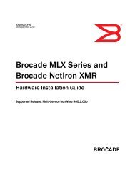
2. Switch Serial Number<br />
The switch serial number and corresponding bar code are provided on the serial number label,<br />
as illustrated below.<br />
<br />
FT00X0054E9<br />
The serial number label is located as follows:<br />
• <strong>Brocade</strong> <strong>Encryption</strong> Switch—On the switch ID pull-out tab located inside the chassis on the<br />
port side of the switch on the left.<br />
• <strong>Brocade</strong> DCX—On the bottom right on the port side of the chassis<br />
• <strong>Brocade</strong> DCX-4S—On the bottom right on the port side of the chassis, directly above the<br />
cable management comb.<br />
• <strong>Brocade</strong> DCX 8510-8—On the port side of the chassis, on the lower right side, and directly<br />
above the cable management comb.<br />
• <strong>Brocade</strong> DCX 8510-4—On the port side of the chassis, on the lower right side and directly<br />
above the cable management comb.<br />
<strong>Fabric</strong> <strong>OS</strong> <strong>Encryption</strong> Administrator’s <strong>Guide</strong> (<strong>KMIP</strong>)<br />
53-1002747-02<br />
xvii
3. World Wide Name (WWN)<br />
Use the licenseIdShow command to display the WWN of the chassis.<br />
If you cannot use the licenseIdShow command because the switch is inoperable, you can get<br />
the WWN from the same place as the serial number, except for the <strong>Brocade</strong> DCX. For the<br />
<strong>Brocade</strong> DCX, access the numbers on the WWN cards by removing the <strong>Brocade</strong> logo plate at<br />
the top of the non-port side of the chassis.<br />
Document feedback<br />
Quality is our first concern at <strong>Brocade</strong> and we have made every effort to ensure the accuracy and<br />
completeness of this document. However, if you find an error or an omission, or you think that a<br />
topic needs further development, we want to hear from you. Forward your feedback to:<br />
documentation@brocade.com<br />
Provide the title and version number of the document and as much detail as possible about your<br />
comment, including the topic heading and page number and your suggestions for improvement.<br />
xviii<br />
<strong>Fabric</strong> <strong>OS</strong> <strong>Encryption</strong> Administrator’s <strong>Guide</strong> (<strong>KMIP</strong>)<br />
53-1002747-02
<strong>Encryption</strong> Overview<br />
Chapter<br />
1<br />
In this chapter<br />
•Host and LUN considerations . . . . . . . . . . . . . . . . . . . . . . . . . . . . . . . . . . . . . . 1<br />
•Terminology . . . . . . . . . . . . . . . . . . . . . . . . . . . . . . . . . . . . . . . . . . . . . . . . . . . . 2<br />
•The <strong>Brocade</strong> <strong>Encryption</strong> Switch . . . . . . . . . . . . . . . . . . . . . . . . . . . . . . . . . . . . 4<br />
•The FS8-18 blade . . . . . . . . . . . . . . . . . . . . . . . . . . . . . . . . . . . . . . . . . . . . . . . 5<br />
•FIPS mode . . . . . . . . . . . . . . . . . . . . . . . . . . . . . . . . . . . . . . . . . . . . . . . . . . . . . 5<br />
•Performance licensing. . . . . . . . . . . . . . . . . . . . . . . . . . . . . . . . . . . . . . . . . . . . 5<br />
•Recommendation for connectivity . . . . . . . . . . . . . . . . . . . . . . . . . . . . . . . . . . 6<br />
•Usage limitations . . . . . . . . . . . . . . . . . . . . . . . . . . . . . . . . . . . . . . . . . . . . . . . . 6<br />
•<strong>Brocade</strong> encryption solution overview . . . . . . . . . . . . . . . . . . . . . . . . . . . . . . . 7<br />
•Data encryption key life cycle management . . . . . . . . . . . . . . . . . . . . . . . . . . 9<br />
•Master key management . . . . . . . . . . . . . . . . . . . . . . . . . . . . . . . . . . . . . . . . 11<br />
•Support for virtual fabrics . . . . . . . . . . . . . . . . . . . . . . . . . . . . . . . . . . . . . . . . 11<br />
•Cisco <strong>Fabric</strong> Connectivity support . . . . . . . . . . . . . . . . . . . . . . . . . . . . . . . . . 12<br />
Host and LUN considerations<br />
Encrypting data-at-rest provides peace of mind in terms of protecting data from loss or theft, but<br />
very careful planning must be done to ensure encrypted data is handled correctly. Much of the<br />
planning must come from careful evaluation of host application and LUN resources, and of the<br />
path that the data will take to get from one or more hosts to a LUN.<br />
CAUTION<br />
When implementing encryption for data-at-rest, all hosts that access a LUN that is to hold<br />
encrypted data need to be configured for encryption to avoid data corruption. If a host, possibly in<br />
another fabric, writes cleartext to an encrypted LUN, the data on the LUN will be lost. The user<br />
must ensure that all hosts that can access a LUN are configured in the same manner.<br />
<strong>Fabric</strong> <strong>OS</strong> <strong>Encryption</strong> Administrator’s <strong>Guide</strong> (<strong>KMIP</strong>) 1<br />
53-1002747-02
1<br />
Terminology<br />
Terminology<br />
The following are definitions of terms used extensively in this document.<br />
ciphertext<br />
cleartext<br />
Encrypted data.<br />
Unencrypted data.<br />
CryptoModule The secure part of an encryption engine that is protected to the FIPS 140-2 level 3<br />
standard. The term CryptoModule is used primarily in the context of FIPS<br />
authentication.<br />
Data <strong>Encryption</strong> Key (DEK)<br />
Data <strong>Encryption</strong> Key Cluster<br />
(DEK Cluster)<br />
<strong>Encryption</strong> Engine<br />
<strong>Encryption</strong> Group<br />
Failback<br />
Failover<br />
Group Leader<br />
High Availability Cluster<br />
(HA Cluster)<br />
An encryption key generated by the encryption engine. The DEK is used to encrypt<br />
cleartext received from a host before it is sent to a target LUN, and to decrypt that data<br />
when it is retrieved by the host.<br />
A cluster of encryption engines which can host all paths to a LUN and share the same<br />
data encryption key (DEK) set. The encryption engines can be in the same or different<br />
fabrics. DEK clusters enable host MPIO failover.<br />
The entity within a node that performs encryption operations, including the generation<br />
of Data <strong>Encryption</strong> Keys.<br />
A collection of one or more DEK clusters, HA clusters, or both, which share the same key<br />
vault and device configuration, and is managed as a single group.<br />
In the context of this implementation of encryption, failback refers to behavior after a<br />
failed encryption switch recovers. Devices that were transferred to another switch by<br />
failover processing may automatically be transferred back, or they may be manually<br />
switched back. This is determined as a configuration option.<br />
In the context of this implementation of encryption, failover refers to the automatic<br />
transfer of devices hosted by one encryption switch to another encryption switch within<br />
a high availability cluster (HA cluster).<br />
A group leader is a special node within an encryption group which acts as a group and<br />
cluster manager, and manages and distributes all group-wide and cluster-wide<br />
configurations to all members of the group or cluster.<br />
A collection of peer-level encryption engines that provide failover capabilities within a<br />
fabric.<br />
Key <strong>Encryption</strong> Key<br />
A key used to encrypt and decrypt Data <strong>Encryption</strong> Keys (DEKs) within encryption<br />
devices so that DEKs are transmitted in a secure manner outside of the encryption<br />
engines, and stored persistently inside key vaults.<br />
Link Key A shared secret exchanged between an encryption engine and a FIPS 140-2 level 3<br />
certified key management appliance and key vault. The link key is an Key <strong>Encryption</strong><br />
Key (KEK) that is used to encrypt Data <strong>Encryption</strong> Keys (DEKs) in transit over a secure<br />
connection to and from the key vault. The key management appliance decrypts the<br />
DEKs and stores them encrypted with its own master key.<br />
Logical Unit Number (LUN)<br />
The identifier of a SCSI logical unit.<br />
Master Key<br />
Node<br />
A Key <strong>Encryption</strong> Key (KEK) used to encrypt and decrypt DEKs when storing DEKs in<br />
opaque key vaults. There is one master key per encryption group. That means all node<br />
encryption engines within an encryption group use the same master key to encrypt and<br />
decrypt the DEKs.<br />
In terms of encryption, a <strong>Brocade</strong> <strong>Encryption</strong> Switch, DCX, or DCX-4S through which<br />
users can manage an encryption engine.<br />
2 <strong>Fabric</strong> <strong>OS</strong> <strong>Encryption</strong> Administrator’s <strong>Guide</strong> (<strong>KMIP</strong>)<br />
53-1002747-02
Terminology 1<br />
Opaque Key Vault<br />
Recovery cards<br />
Redirection zone<br />
Rekeying<br />
Trusted Key Vault<br />
Virtual Initiator<br />
Virtual Target<br />
A storage location that provides untrusted key management functionality. Its contents<br />
may be visible to a third party. DEKs in an opaque key vault are stored encrypted in a<br />
master key to protect them.<br />
A set of smart cards that contain a backup master key. Each recovery card holds a<br />
portion of the master key. The cards must be gathered and read together from a card<br />
reader attached to a PC running the BNA client to restore the master key. Recovery<br />
cards may be stored in different locations, making it very difficult to steal the master<br />
key. The cards should not be stored together, as that defeats the purpose.<br />
When encryption is implemented, data traffic is routed to and from virtual initiators and<br />
virtual targets. Redirection zones are automatically created to enable frame redirection<br />
to the virtual initiators and virtual targets.<br />
Rekeying refers to decrypting data with the current Data <strong>Encryption</strong> Key (DEK), and<br />
encrypting it with a new DEK. This is done when the security of the current key is<br />
compromised, or when a DEK is configured to expire in a specific time frame. The<br />
rekeying operation can be used to encrypt existing data currently stored as cleartext. In<br />
that case, there is no existing DEK, and the data does not have to be decrypted before it<br />
is encrypted using the new DEK.<br />
Very secure storage on a hardware appliance that establishes a trusted link with the<br />
encryption device for secure exchange of DEKs. DEKs are encrypted with the link for<br />
transit between the encryption device and the hardware appliance. At the hardware<br />
appliance, the DEKs are re-encrypted, using master key created and maintained by<br />
hardware appliance, and then stored in the trusted key vault.<br />
A logical entity that acts as a stand-in for a physical host when communicating with a<br />
physical target LUN.<br />
A logical entity that acts as a stand-in for a physical target LUN when communicating<br />
with a physical host. A virtual target is mapped one to one to a specific physical target.<br />
<strong>Fabric</strong> <strong>OS</strong> <strong>Encryption</strong> Administrator’s <strong>Guide</strong> (<strong>KMIP</strong>) 3<br />
53-1002747-02
1<br />
The <strong>Brocade</strong> <strong>Encryption</strong> Switch<br />
The <strong>Brocade</strong> <strong>Encryption</strong> Switch<br />
The <strong>Brocade</strong> <strong>Encryption</strong> Switch is a high-performance, 32-port, auto-sensing 8 Gbps Fibre Channel<br />
switch with data cryptographic (encryption/decryption) and data compression capabilities. The<br />
switch is a network-based solution that secures data-at-rest for heterogeneous tape drives, disk<br />
array LUNs, and virtual tape libraries by encrypting the data using Advanced <strong>Encryption</strong> Standard<br />
(AES) 256-bit algorithms. <strong>Encryption</strong> and decryption engines provide in-line encryption services<br />
with up to 96 Gbps throughput for disk I/O (mix of ciphertext and cleartext traffic) and up to 48<br />
Gbps throughput for tape I/O (mix of ciphertext and cleartext traffic). Refer to “The FS8-18 blade”<br />
on page 5 for information about license requirements for 48 Gbps and 96 Gbps throughput.<br />
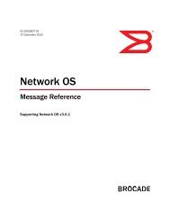
In addition to its 32 Fibre Channel ports, the switch has one RJ45 Gigabit Ethernet (GE)<br />
management port, two RJ45 GE ports for clustering interconnection and rekey synchronization, one<br />
RJ-45 Serial console port, and one USB port for serviceability, error logging, and firmware upgrades<br />
(Figure 1) .<br />
FIGURE 1<br />
<strong>Brocade</strong> <strong>Encryption</strong> Switch<br />
1 Power LED.<br />
2 Status LED.<br />
3 RJ-45 gigabit Ethernet ports (labeled eth0 and eth1) for clustering and centralized<br />
management of multiple encryption switches through a group leader.<br />
4 Smart card reader.<br />
5 RJ-45 gigabit Ethernet port for the management interface. This interface is used for the secure<br />
connection to the key vault location and to the BNA client.<br />
6 RJ-45 serial console port.<br />
7 USB port for firmware upgrades and other support services.<br />
8 Fibre Channel ports (0-31) - 1, 2, 4, or 8 Gbps auto-sensing F, FL, E, EX, or M ports to connect<br />
host servers, SAN disks, SAN tapes, edge switches, or core switches.<br />
4 <strong>Fabric</strong> <strong>OS</strong> <strong>Encryption</strong> Administrator’s <strong>Guide</strong> (<strong>KMIP</strong>)<br />
53-1002747-02
The FS8-18 blade 1<br />
The FS8-18 blade<br />
The FS8-18 blade provides the same features and functionality as the <strong>Brocade</strong> <strong>Encryption</strong> Switch.<br />
The FS8-18 blade installs on the <strong>Brocade</strong> DCX Backbone chassis, which include the DCX, DCX-4S,<br />
DCX 8510-8, and DCX 8510-4 chassis.<br />
FIPS mode<br />
Both the <strong>Brocade</strong> <strong>Encryption</strong> Switch and the FS8-18 blade always boot up in FIPS mode, which<br />
cannot be disabled. In this mode, only FIPS-compliant algorithms are allowed.<br />
Performance licensing<br />
<strong>Encryption</strong> processing power is scalable, and may be increased by purchasing and installing an<br />
encryption performance license. The base unit <strong>Brocade</strong> <strong>Encryption</strong> Switch and FS8-18 <strong>Encryption</strong><br />
Blade have a standard capacity of 48 Gbps of encryption processing power. Additional encryption<br />
processing power can be added for disk I/O by purchasing and installing an Advanced Disk<br />
<strong>Encryption</strong> Performance Upgrade license. When the performance upgrade license is applied,<br />
encryption processing power of up to 96 Gbps is available for disk encryption. Note that when the<br />
license is applied to a <strong>Brocade</strong> DCX Backbone chassis, it applies to all FS8-18 blades installed on<br />
that chassis.<br />
Adding a license<br />
The encryption performance licenses are added just like any other <strong>Fabric</strong> <strong>OS</strong> feature license. After<br />
the license is added, the <strong>Brocade</strong> <strong>Encryption</strong> Switch and <strong>Brocade</strong> DCX Backbone chassis with<br />
encryption blades installed must be rebooted for the license to take effect. See the <strong>Fabric</strong> <strong>OS</strong><br />
Administrator’s <strong>Guide</strong> for information about obtaining and adding licenses.<br />
Licensing best practices<br />
Licenses installed on the switches and blades must have identical performance numbers when<br />
used together in high availability (HA) clusters or data encryption key (DEK) clusters.<br />
<strong>Fabric</strong> <strong>OS</strong> <strong>Encryption</strong> Administrator’s <strong>Guide</strong> (<strong>KMIP</strong>) 5<br />
53-1002747-02
1<br />
Recommendation for connectivity<br />
Recommendation for connectivity<br />
In order to achieve high performance and throughput, the encryption engines perform what is<br />
referred to as “cut-through” encryption. In simple terms, this is achieved by encrypting the data in<br />
data frames on a per-frame basis. This enables the encryption engine to buffer only one frame,<br />
encrypt it, and send out the frame to the target on write I/Os. For read I/Os, the reverse is done.<br />
This puts some constraints on the topology and the container configurations to support acceptable<br />
performance for encrypted and decrypted I/O to and from LUNs, and to support acceptable levels<br />
of scale in terms of the number of LUNs and the number of flows. The topology and container<br />
configuration constraint are stated below:<br />
Care must be taken when connecting the encryption engines to the fabric and configuring<br />
crypto-target containers to be sure that the traffic flow between the host initiator and the physical<br />
storage array LUN through the container flows through only one encryption engine that is hosting<br />
the container. This is to avoid crisscrossing of flows to and from virtual entities; that is, from virtual<br />
targets and virtual initiators on two different encryption engines over the same path.<br />
Although there is considerable flexibility in connecting and configuring the containers for<br />
encryption, the following guidelines are the recommended best practices:<br />
• Host and storage array ports that are not involved in any encryption flow can be connected to<br />
any encryption engines (EEs).<br />
• Recommendations for host and target ports with respect to encryption flows are as follows:<br />
- For high availability (HA) purposes, only ISLs are connected to the encryption engine to<br />
connect it to the fabric. No devices (initiators and targets) are connected to it.<br />
- To maintain HA, we recommend that devices (hosts and targets) and ISLs not be<br />
connected directly to the encryption blades (FS8-18) in a <strong>Brocade</strong> DCX Backbone chassis<br />
in a single-path configuration.<br />
Usage limitations<br />
There are usage limitations to be aware of when planning an encryption implementation:<br />
• Special redirection zones are created to handle data that is redirected to an encryption switch<br />
or blade. Quality of Service (QoS) cannot be applied to a redirection zone.<br />
• For frame redirection to be applied, regular zones for hosts and targets must be defined in the<br />
effective configuration. Hosts and targets must be zoned together by worldwide port name<br />
(WWPN) rather than worldwide node name (WWNN) in configurations where frame redirection<br />
will be used. If hosts or targets are zoned together using worldwide node name, frame<br />
redirection will not occur properly.<br />
NOTE<br />
The use of alias names in place of WWPNs is not supported.<br />
• On tapes written in DataFort format, the encryption switch or blade cannot read and decrypt<br />
files with a block size of 1 MB or greater.<br />
• The Top Talker feature is not compatible with redirection zones. The Top Talker feature should<br />
not be enabled when an encryption switch or blade is present in the fabric.<br />
6 <strong>Fabric</strong> <strong>OS</strong> <strong>Encryption</strong> Administrator’s <strong>Guide</strong> (<strong>KMIP</strong>)<br />
53-1002747-02
<strong>Brocade</strong> encryption solution overview 1<br />
<strong>Brocade</strong> encryption solution overview<br />
The loss of stored private data, trade secrets, intellectual properties, and other sensitive<br />
information through theft, or accidental loss of disk or tape media can have widespread negative<br />
consequences for governments, businesses, and individuals. This threat is countered by an<br />
increasing demand from governments and businesses for solutions that create and enforce<br />
policies and procedures that protect stored data. <strong>Encryption</strong> is a powerful tool for data protection.<br />
<strong>Brocade</strong> provides an encryption solution that resides in a Storage Area Network (SAN) fabric. This<br />
location, between computers and storage, is ideal for implementing a solution that works<br />
transparently with heterogeneous servers, disk storage subsystems, and tape libraries. Data<br />
entering the SAN from a server is encrypted before it is written to storage. When stored data is<br />
encrypted, theft or loss of storage media does not pose a security threat.<br />
Figure 2 provides a high-level view of the <strong>Brocade</strong> encryption solution. Cleartext is sent from the<br />
server to the encryption engine, where it is encrypted into ciphertext using one of two encryption<br />
algorithms: one for disk storage targets, and one for tape storage targets. The encrypted data<br />
cannot be read without first being decrypted. The key management system is required for<br />
management of the data encryption keys (DEKs) that are generated by the encryption engine, and<br />
used for encrypting and decrypting the data. The key management system is provided by a<br />
third-party vendor.<br />
FIGURE 2<br />
<strong>Encryption</strong> overview<br />
<strong>Fabric</strong> <strong>OS</strong> <strong>Encryption</strong> Administrator’s <strong>Guide</strong> (<strong>KMIP</strong>) 7<br />
53-1002747-02
1<br />
<strong>Brocade</strong> encryption solution overview<br />
Data flow from server to storage<br />
The <strong>Brocade</strong> <strong>Encryption</strong> Switch can be introduced into a SAN with minimum disruption, with no<br />
need for SAN reconfiguration, and with no need to reconfigure host applications. Frames sent from<br />
a host and a target LUN are redirected to a virtual target associated with the encryption switch. The<br />
encryption switch then acts as a virtual initiator to forward the frames to the target LUN.<br />
FIGURE 3<br />
Frame redirection<br />
8 <strong>Fabric</strong> <strong>OS</strong> <strong>Encryption</strong> Administrator’s <strong>Guide</strong> (<strong>KMIP</strong>)<br />
53-1002747-02
Data encryption key life cycle management 1<br />
Data encryption key life cycle management<br />
Data encryption keys (DEKs) are generated by the encryption engine. Data is encrypted and<br />
decrypted using the same DEK, so a DEK must be preserved at least long enough to decrypt the<br />
ciphertext that it created. The length of time data is stored before it is retrieved can vary greatly,<br />
and some data may be stored for years or decades before it is accessed. To be sure the data<br />
remains accessible, DEKs may also need to be stored for years or decades. Key management<br />
systems provide life-cycle management for all DEKs created by the encryption engine. Key<br />
management systems are provided by third-party vendors.<br />
Figure 4 shows the relationship of the LAN connections to the key vault and between encryption<br />
nodes.<br />
Key Management<br />
System<br />
LAN<br />
<strong>Encryption</strong> Group<br />
Node 1<br />
Node 2<br />
Node 3<br />
Node 4<br />
EE<br />
EE<br />
EE<br />
EE<br />
Group Leader<br />
IO Sync LAN<br />
FIGURE 4<br />
LAN connections to the key vault, and between encryption nodes<br />
Regardless of the length of the life cycle, there are four stages in the life of a DEK, as shown in<br />
Figure 5. A DEK is created by an encryption engine, distributed, then stored in a key vault. The key<br />
is used to encrypt and decrypt data at least once, and possibly many times. A DEK may be<br />
configured to expire in a certain time frame to avoid becoming compromised. Under those<br />
conditions, it must be used one more time to decrypt the data, and the resulting cleartext is<br />
encrypted with a new key (rekeyed).<br />
<strong>Fabric</strong> <strong>OS</strong> <strong>Encryption</strong> Administrator’s <strong>Guide</strong> (<strong>KMIP</strong>) 9<br />
53-1002747-02
1<br />
Data encryption key life cycle management<br />
FIGURE 5<br />
DEK life cycle<br />
10 <strong>Fabric</strong> <strong>OS</strong> <strong>Encryption</strong> Administrator’s <strong>Guide</strong> (<strong>KMIP</strong>)<br />
53-1002747-02
Master key management 1<br />
Master key management<br />
Communications with opaque key vaults are encrypted using a master key that is created by the<br />
encryption engine on the encryption switch. Currently, this includes the key vaults of all supported<br />
key management systems except NetApp LKM.<br />
Master key generation<br />
A master key must be generated by the group leader encryption engine. The master key can be<br />
generated once by the group leader, then propagated to the other members of an encryption group.<br />
Master key backup<br />
It is essential to back up the master key immediately after it is generated. The master key may be<br />
backed up to any of the following:<br />
• A file as an encrypted key.<br />
• The key management system as an encrypted key record.<br />
• A set of recovery smart cards. This option is available only if the switch is managed by the<br />
<strong>Brocade</strong> Network Advisor (BNA) application (also referred to as the Management application),<br />
and if a card reader is available for attachment to the BNA workstation.<br />
The use of smart cards provides the highest level of security. When smart cards are used, the<br />
key is split and written on up to 10 cards. Each card may be kept and stored by a different<br />
individual. A quorum of key holders is needed to restore the key. If five key holders exist and<br />
the quorum is set to three, then any three of the five key holders is needed to restore the key.<br />
Support for virtual fabrics<br />
The <strong>Brocade</strong> <strong>Encryption</strong> Switch does not support the logical switch partitioning capability and, thus,<br />
cannot be partitioned, but the switch can be connected to any Logical Switch partition or Logical<br />
<strong>Fabric</strong> using an E_Port.<br />
The FS8-18 <strong>Encryption</strong> Blades are supported only in a default switch partition. All FS8-18 blades<br />
must be placed in a default switch partition in a DCX Backbone chassis. The encryption resource<br />
from the default switch partition/fabric can be shared with other logical switch partitions/fabrics or<br />
other fabrics only through external device sharing using FCR or EX_Ports through a base<br />
switch/fabric. A separate port blade must be used in the base switch/fabric for EX_Port<br />
connectivity from the logical switch partition (default switch partition) of FS8-18 blades and<br />
host/target fabrics. The EX_Port can be on any external FCR switch.<br />
NOTE<br />
Refer to the <strong>Fabric</strong> <strong>OS</strong> Administrator’s <strong>Guide</strong> for details on how to configure the <strong>Brocade</strong> DCX<br />
Backbones in virtual fabrics environments, including configuration of default switch partition and<br />
any other logical switch partitions.<br />
<strong>Fabric</strong> <strong>OS</strong> <strong>Encryption</strong> Administrator’s <strong>Guide</strong> (<strong>KMIP</strong>) 11<br />
53-1002747-02
1<br />
Cisco <strong>Fabric</strong> Connectivity support<br />
Cisco <strong>Fabric</strong> Connectivity support<br />
The <strong>Brocade</strong> <strong>Encryption</strong> Switch provides NPIV mode connectivity to Cisco fabrics. Connectivity is<br />
supported for Cisco SAN <strong>OS</strong> 3.3 and later versions.<br />
Cisco fabric connectivity is provided only on the <strong>Brocade</strong> <strong>Encryption</strong> Switch. The FS8-18 blade for<br />
the <strong>Brocade</strong> DCX Backbone chassis does not support this feature.<br />
12 <strong>Fabric</strong> <strong>OS</strong> <strong>Encryption</strong> Administrator’s <strong>Guide</strong> (<strong>KMIP</strong>)<br />
53-1002747-02
Configuring <strong>Encryption</strong> Using the Management Application<br />
Chapter<br />
2<br />
In this chapter<br />
•<strong>Encryption</strong> Center features . . . . . . . . . . . . . . . . . . . . . . . . . . . . . . . . . . . . . . . 14<br />
•<strong>Encryption</strong> user privileges. . . . . . . . . . . . . . . . . . . . . . . . . . . . . . . . . . . . . . . . 15<br />
•Smart card usage . . . . . . . . . . . . . . . . . . . . . . . . . . . . . . . . . . . . . . . . . . . . . . 16<br />
•Network connections. . . . . . . . . . . . . . . . . . . . . . . . . . . . . . . . . . . . . . . . . . . . 26<br />
•Blade processor links . . . . . . . . . . . . . . . . . . . . . . . . . . . . . . . . . . . . . . . . . . . 27<br />
•<strong>Encryption</strong> node initialization and certificate generation. . . . . . . . . . . . . . . 28<br />
•Key Management Interoperability Protocol . . . . . . . . . . . . . . . . . . . . . . . . . . 29<br />
•Steps for connecting to a <strong>KMIP</strong> appliance (SafeNet KeySecure). . . . . . . . . 29<br />
•<strong>Encryption</strong> preparation . . . . . . . . . . . . . . . . . . . . . . . . . . . . . . . . . . . . . . . . . . 49<br />
•Creating an encryption group . . . . . . . . . . . . . . . . . . . . . . . . . . . . . . . . . . . . . 50<br />
•Adding a switch to an encryption group. . . . . . . . . . . . . . . . . . . . . . . . . . . . . 61<br />
•Replacing an encryption engine in an encryption group . . . . . . . . . . . . . . . 67<br />
•High availability (HA) clusters . . . . . . . . . . . . . . . . . . . . . . . . . . . . . . . . . . . . . 68<br />
•Configuring encryption storage targets . . . . . . . . . . . . . . . . . . . . . . . . . . . . . 71<br />
•Configuring hosts for encryption targets . . . . . . . . . . . . . . . . . . . . . . . . . . . . 80<br />
•Adding target disk LUNs for encryption . . . . . . . . . . . . . . . . . . . . . . . . . . . . . 82<br />
•Adding target tape LUNs for encryption. . . . . . . . . . . . . . . . . . . . . . . . . . . . . 87<br />
•Moving Targets. . . . . . . . . . . . . . . . . . . . . . . . . . . . . . . . . . . . . . . . . . . . . . . . . 90<br />
•Configuring encrypted tape storage in a multi-path environment . . . . . . . . 91<br />
•Tape LUN write early and read ahead . . . . . . . . . . . . . . . . . . . . . . . . . . . . . . 92<br />
•Tape LUN statistics . . . . . . . . . . . . . . . . . . . . . . . . . . . . . . . . . . . . . . . . . . . . . 93<br />
•<strong>Encryption</strong> engine rebalancing . . . . . . . . . . . . . . . . . . . . . . . . . . . . . . . . . . . . 98<br />
•Master keys . . . . . . . . . . . . . . . . . . . . . . . . . . . . . . . . . . . . . . . . . . . . . . . . . . . 99<br />
•Security Settings . . . . . . . . . . . . . . . . . . . . . . . . . . . . . . . . . . . . . . . . . . . . . . 109<br />
•Zeroizing an encryption engine . . . . . . . . . . . . . . . . . . . . . . . . . . . . . . . . . . 109<br />
•Using the <strong>Encryption</strong> Targets dialog box . . . . . . . . . . . . . . . . . . . . . . . . . . . 111<br />
•Redirection zones . . . . . . . . . . . . . . . . . . . . . . . . . . . . . . . . . . . . . . . . . . . . . 112<br />
•Disk device decommissioning . . . . . . . . . . . . . . . . . . . . . . . . . . . . . . . . . . . 112<br />
•Rekeying all disk LUNs manually . . . . . . . . . . . . . . . . . . . . . . . . . . . . . . . . . 115<br />
•Thin provisioned LUNs. . . . . . . . . . . . . . . . . . . . . . . . . . . . . . . . . . . . . . . . . . 120<br />
•Viewing time left for auto rekey . . . . . . . . . . . . . . . . . . . . . . . . . . . . . . . . . . 121<br />
•Viewing and editing switch encryption properties. . . . . . . . . . . . . . . . . . . . 122<br />
<strong>Fabric</strong> <strong>OS</strong> <strong>Encryption</strong> Administrator’s <strong>Guide</strong> (<strong>KMIP</strong>) 13<br />
53-1002747-02
2<br />
<strong>Encryption</strong> Center features<br />
•Viewing and editing encryption group properties . . . . . . . . . . . . . . . . . . . . 126<br />
•<strong>Encryption</strong>-related acronyms in log messages . . . . . . . . . . . . . . . . . . . . . . 140<br />
<strong>Encryption</strong> Center features<br />
The <strong>Encryption</strong> Center dialog box is the single launching point for all encryption-related<br />
configuration in the <strong>Brocade</strong> Network Advisor (BNA) Management application (Figure 6). It also<br />
provides a table that shows the general status of all encryption-related hardware and functions at a<br />
glance. To open the dialog box, select Configure > <strong>Encryption</strong>.<br />
FIGURE 6<br />
<strong>Encryption</strong> Center dialog box<br />
Beginning with <strong>Fabric</strong> <strong>OS</strong> 6.4, the <strong>Encryption</strong> Center is dynamically updated to reflect the latest<br />
changes based on any of the following events:<br />
• <strong>Encryption</strong> group creation or deletion.<br />
• A change in encryption group status or encryption engine status<br />
• Addition or removal of an encryption group member or encryption engine<br />
If you are using the <strong>Encryption</strong> Center for the first time, please read the following topics before you<br />
begin to perform encryption operations:<br />
• “<strong>Encryption</strong> user privileges” on page 15 describes the Role-based Access Control privileges<br />
that are specific to encryption.<br />
• “Smart card usage” on page 16 and the topics that follow describe the options available for the<br />
use of Smart Cards for user authentication, system access control, and storing backup copies<br />
of data encryption master keys.<br />
• “Network connections” on page 26 describes the network connections that must be in place to<br />
enable encryption.<br />
• “Blade processor links” on page 27 describes the steps for interconnecting encryption<br />
switches or blades in an encryption group through a dedicated LAN. This must be done before<br />
the encryption engines are enabled. Security parameters and certificates cannot be<br />
exchanged if these links are not configured and active.<br />
• “<strong>Encryption</strong> node initialization and certificate generation” on page 28 lists the security<br />
parameters and certificates that are generated when an encryption node is initialized.<br />
14 <strong>Fabric</strong> <strong>OS</strong> <strong>Encryption</strong> Administrator’s <strong>Guide</strong> (<strong>KMIP</strong>)<br />
53-1002747-02
<strong>Encryption</strong> user privileges 2<br />
<strong>Encryption</strong> user privileges<br />
In BNA, resource groups are assigned privileges, roles, and fabrics. Privileges are not directly<br />
assigned to users; users get privileges because they belong to a role in a resource group. A user<br />
can only belong to one resource group at a time.<br />
BNA provides three pre-configured roles:<br />
• Storage encryption configuration<br />
• Storage encryption key operations<br />
• Storage encryption security<br />
Table 1 lists the associated roles and their read/write access to specific operations. The functions<br />
are enabled from the <strong>Encryption</strong> Center dialog box:<br />
TABLE 1<br />
Privilege<br />
<strong>Encryption</strong> privileges<br />
Read/Write<br />
Storage <strong>Encryption</strong><br />
Configuration<br />
Storage <strong>Encryption</strong> Key<br />
Operations<br />
• Launch the <strong>Encryption</strong> center dialog box.<br />
• View switch, group, or engine properties.<br />
• View the <strong>Encryption</strong> Group Properties Security tab.<br />
• View encryption targets, hosts, and LUNs.<br />
• View LUN centric view<br />
• View all rekey sessions<br />
• Add/remove paths and edit LUN configuration on LUN centric view<br />
• Rebalance encryption engines.<br />
• Clear tape LUN statistics<br />
• Create a new encryption group or add a switch to an existing encryption group.<br />
• Edit group engine properties (except for the Security tab)<br />
• Add targets.<br />
• Select encryption targets and LUNs to be encrypted or edit LUN encryption settings.<br />
• Edit encryption target hosts configuration.<br />
• Show tape LUN statistics.<br />
• Launch the <strong>Encryption</strong> center dialog box.<br />
• View switch, group, or engine properties,<br />
• View the <strong>Encryption</strong> Group Properties Security tab.<br />
• View encryption targets, hosts, and LUNs.<br />
• View LUN centric view.<br />
• View all rekey sessions.<br />
• Initiate manual rekeying of all disk LUNs.<br />
• Initiate refresh DEK.<br />
• Enable and disable an encryption engine.<br />
• Decommission LUNs.<br />
• Zeroize an encryption engine.<br />
• Restore a master key.<br />
• Edit key vault credentials.<br />
• Show tape LUN statistics.<br />
<strong>Fabric</strong> <strong>OS</strong> <strong>Encryption</strong> Administrator’s <strong>Guide</strong> (<strong>KMIP</strong>) 15<br />
53-1002747-02
2<br />
Smart card usage<br />
TABLE 1<br />
Privilege<br />
<strong>Encryption</strong> privileges (Continued)<br />
Read/Write<br />
Storage <strong>Encryption</strong><br />
Security<br />
• Launch the <strong>Encryption</strong> center dialog box.<br />
• View switch, group, or engine properties.<br />
• View <strong>Encryption</strong> Group Properties Security tab.<br />
• View LUN centric view.<br />
• View all rekey sessions.<br />
• View encryption targets, hosts, and LUNs.<br />
• Create a master key.<br />
• Backup a master key.<br />
• Edit smart card.<br />
• View and modify settings on the <strong>Encryption</strong> Group Properties Security tab (quorum size,<br />
authentication cards list and system card requirement).<br />
• Establish link keys for LKM key managers.<br />
• Show tape LUN statistics.<br />
Smart card usage<br />
Smart Cards are credit card-sized cards that contain a CPU and persistent memory. Smart cards<br />
can be used as security devices. You must have Storage <strong>Encryption</strong> Security user privileges to<br />
activate, register, and configure smart cards.<br />
Smart cards can be used to do the following:<br />
• Control user access to the BNA security administrator roles<br />
• Control activation of encryption engines<br />
• Securely store backup copies of master keys<br />
Smart card readers provide a plug-and-play interface that allows you to read and write to a smart<br />
card. The following smart card readers are supported:<br />
• GemPlus GemPC USB<br />
http://www.gemalto.com/readers/index.html<br />
• SCM MicrosystemsSCR331<br />
http://www.scmmicro.com/security/view_product_en.php?PID=2<br />
NOTE<br />
Only the <strong>Brocade</strong> smart cards that are included with the encryption switches are supported.<br />
Using authentication cards with a card reader<br />
When authentication cards are used, one or more authentication cards must be read by a card<br />
reader attached to a BNA workstation to enable certain security-sensitive operations. These<br />
include the following:<br />
• Performing master key generation, backup, and restore operations.<br />
• Registering or deregistering and replacement of authentication cards.<br />
• Enabling and disabling the use of system cards.<br />
• Changing the quorum size for authentication cards.<br />
16 <strong>Fabric</strong> <strong>OS</strong> <strong>Encryption</strong> Administrator’s <strong>Guide</strong> (<strong>KMIP</strong>)<br />
53-1002747-02
Smart card usage 2<br />
• Establishing a trusted link with the NetApp LKM key vault.<br />
• Decommissioning a LUN.<br />
When a quorum of authentication cards is registered for use, authentication must be provided<br />
before you are granted access.<br />
Registering authentication cards from a card reader<br />
To register an authentication card or a set of authentication cards from a card reader, have the<br />
cards physically available. Authentication cards can be registered during encryption group or<br />
member configuration when running the configuration wizard, or they can be registered using the<br />
following procedure.<br />
1. Select Configure > <strong>Encryption</strong> from the menu task bar to display the <strong>Encryption</strong> Center<br />
dialog box (Refer to Figure 6 on page 14).<br />
2. Select an encryption group from the <strong>Encryption</strong> Center Devices table, then select Group ><br />
Security from the menu task bar to display the <strong>Encryption</strong> Group Properties dialog box. The<br />
Security tab is selected (Figure 7).<br />
FIGURE 7<br />
<strong>Encryption</strong> Group Properties dialog box - registering authentication cards<br />
The dialog box contains the following information:<br />
• Group Card#: A number assigned to the card as it is registered.<br />
• Card ID: The serial number read from the smart card.<br />
• First Name: The first name of the person assigned to the card.<br />
• Last Name: The last name of the person assigned to the card.<br />
• Notes: An optional entry of information.<br />
• Register from Card Reader button: Launches the Add Authentication Card dialog box.<br />
• Register from Archive button: Launches the Add Authentication Card dialog box.<br />
• Deregister button: Deregisters a card selected from the Registered Authentication Cards<br />
table, which enables the cards to be removed from the switch and the database.<br />
<strong>Fabric</strong> <strong>OS</strong> <strong>Encryption</strong> Administrator’s <strong>Guide</strong> (<strong>KMIP</strong>) 17<br />
53-1002747-02
2<br />
Smart card usage<br />
3. Locate the Authentication Card Quorum Size and select the quorum size from the list.<br />
The quorum size is the minimum number of cards necessary to enable the card holders to<br />
perform the security sensitive operations listed above. The maximum quorum size is five cards.<br />
The actual number of authentication cards registered is always more than the quorum size, so<br />
if you set the quorum size to five, for example, you will need to register at least six cards in the<br />
subsequent steps.<br />
NOTE<br />
Ignore the System Cards setting for now.<br />
4. Click Register from Card Reader to register a new card.<br />
The Add Authentication Card dialog box displays (Figure 8).<br />
FIGURE 8<br />
Add Authentication Card dialog box<br />
The dialog box contains the following information:<br />
• Card Serial#: A serial number read from the smart card.<br />
• Card Assignment: The first and last name of the person assigned to the card.<br />
• Notes: An optional entry of information.<br />
• Card Password: Create a password for the card holder to enter for user verification.<br />
• Re-type Password: Re-enter the password in this field.<br />
• Status: Indicates the status when a card is being registered.<br />
5. Insert a smart card into the card reader. Wait for the card serial number to appear, enter card<br />
assignment information as directed, then click OK.<br />
6. Wait for the confirmation dialog box indicating initialization is done, then click OK.<br />
The card is added to the Registered Authentication Cards table.<br />
7. Repeat step 5 through step 6 until you have successfully registered all cards. Ensure that the<br />
number of cards registered equals at least the quorum size plus one.<br />
18 <strong>Fabric</strong> <strong>OS</strong> <strong>Encryption</strong> Administrator’s <strong>Guide</strong> (<strong>KMIP</strong>)<br />
53-1002747-02
Smart card usage 2<br />
Registering authentication cards from the database<br />
Smart cards that are already in the Management program’s database can be registered as<br />
authentication cards.<br />
1. Select Configure > <strong>Encryption</strong> from the menu task bar to display the <strong>Encryption</strong> Center<br />
dialog box (Refer to Figure 6 on page 14).<br />
2. Select an encryption group from the <strong>Encryption</strong> Center Devices table, then select Group ><br />
Security from the menu task bar to display the <strong>Encryption</strong> Group Properties dialog box. The<br />
Security tab is selected (Figure 9).<br />
FIGURE 9<br />
<strong>Encryption</strong> Group Properties dialog box - Security tab<br />
3. Click Register from Archive.<br />
The Authentication Cards dialog box displays (Figure 10). The table lists the smart cards that<br />
are in the database.<br />
FIGURE 10<br />
Authentication Cards dialog box - registering smart cards from archive<br />
4. Select a card from the table, then click OK.<br />
5. Wait for the confirmation dialog box indicating initialization is done, then click OK.<br />
The card is added to the Registered Authentication Cards table.<br />
<strong>Fabric</strong> <strong>OS</strong> <strong>Encryption</strong> Administrator’s <strong>Guide</strong> (<strong>KMIP</strong>) 19<br />
53-1002747-02
2<br />
Smart card usage<br />
Deregistering an authentication card<br />
Authentication cards can be removed from the database and the switch by deregistering them.<br />
Complete the following procedure to deregister an authentication card.<br />
1. Select Configure > <strong>Encryption</strong> from the menu task bar to display the <strong>Encryption</strong> Center<br />
dialog box (Refer to Figure 6 on page 14).<br />
2. Select an encryption group from the <strong>Encryption</strong> Center Devices table, then select Group ><br />
Security from the menu task bar to display the <strong>Encryption</strong> Group Properties dialog box. The<br />
Security tab is selected.<br />
3. Select the desired authentication card in the Registered Authentication Cards table, then click<br />
Deregister.<br />
4. Click Yes to confirm deregistration.<br />
The registered authentication card is removed from the table.<br />
5. Click OK.<br />
The card is deregistered from the group.<br />
Setting a quorum for authentication cards<br />
To authenticate using a quorum of authentication cards, complete the following steps:<br />
1. When using the Authenticate dialog box, gather the number of cards needed according to the<br />
instructions in the dialog box. The registered cards and the assigned owners are listed in the<br />
table near the bottom of the dialog box.<br />
The dialog box contains the following information:<br />
• Card ID: Insert a smart card into an attached card reader, and wait for the card ID to<br />
appear in this field.<br />
• Password: The card holder must enter a password for the card.<br />
• Authenticate button: Authenticates the card after entering the password.<br />
• Currently registered authentication cards table: Lists the currently registered cards,<br />
showing the card ID and the name of the person assigned to the card.<br />
• Status: Displays the status of the card authentication operation.<br />
2. Insert a card, then wait for the ID to appear in the Card ID field.<br />
3. Enter the assigned password, then click Authenticate.<br />
4. Wait for the confirmation dialog box, then click OK.<br />
5. Repeat step 2 through step 4 for each card until at least the quorum plus one is reached, then<br />
click OK.<br />
20 <strong>Fabric</strong> <strong>OS</strong> <strong>Encryption</strong> Administrator’s <strong>Guide</strong> (<strong>KMIP</strong>)<br />
53-1002747-02
Smart card usage 2<br />
Using system cards<br />
System cards are smart cards that can be used to control activation of encryption engines. You can<br />
choose whether the use of a system card is required or not. <strong>Encryption</strong> switches and blades have a<br />
card reader that enables the use of a system card. System cards discourage theft of encryption<br />
switches or blades by requiring the use of a system card at the switch or blade to enable the<br />
encryption engine after a power off.<br />
When the switch or blade is powered off, the encryption engine will not work without first inserting<br />
a system card into its card reader. If someone removes a switch or blade with the intent of<br />
accessing the encryption engine, it will function as an ordinary FC switch or blade when it is<br />
powered up, but use of the encryption engine is denied.<br />
To register a system card from a card reader, the smart card must be physically available.<br />
FIGURE 11<br />
System Cards dialog box<br />
The System Cards dialog box can be accessed by selecting a switch from the <strong>Encryption</strong> Center<br />
Devices table, then selecting Switch > System Cards from the menu task bar. The Register System<br />
Card dialog box displays.<br />
The dialog box contains the following information:<br />
• Group System Card: Identifies if smart cards are used to control activation of encryption<br />
engines.<br />
• Registered System Cards table: Lists all currently registered system card serial numbers and to<br />
whom the cards are assigned by first and last name. Also included are any free-form notes<br />
related to the cards.<br />
• Register from Card Reader button: Launches the Register from Card Reader dialog box.<br />
• Deregister button: Launches the Deregister dialog box.<br />
<strong>Fabric</strong> <strong>OS</strong> <strong>Encryption</strong> Administrator’s <strong>Guide</strong> (<strong>KMIP</strong>) 21<br />
53-1002747-02
2<br />
Smart card usage<br />
Enabling or disabling the system card requirement<br />
To use a system card to control activation of an encryption engine on a switch, you must enable the<br />
system card requirement. If a system card is required, it must be read by the card reader on the<br />
switch. You access the system card GUI from the Security tab.<br />
Complete the following procedure to enable or disable the system card requirement.<br />
1. Select Configure > <strong>Encryption</strong> from the menu task bar to display the <strong>Encryption</strong> Center<br />
dialog box (Refer to Figure 6 on page 14).<br />
2. Select a switch from the <strong>Encryption</strong> Center Devices table, then select Switch > System Cards<br />
from the menu task bar.<br />
The System Cards dialog box displays. (Refer to Figure 11 on page 21.)<br />
3. Do one of the following:<br />
• Set System Cards to Required to require the use of a system card for controlling activation<br />
of the encryption engine.<br />
• Set System Cards to Not Required to permit activation of the encryption engine without the<br />
need to read a system card first.<br />
4. Click OK.<br />
Registering systems card from a card reader<br />
To register a system card from a card reader, a smart card must be physically available. System<br />
cards can be registered during encryption group creation or member configuration when running<br />
the configuration wizard, or they can be registered using the following procedure:<br />
1. Select Configure > <strong>Encryption</strong> from the menu task bar to display the <strong>Encryption</strong> Center<br />
dialog box (Refer to Figure 6 on page 14).<br />
2. Select a switch from the <strong>Encryption</strong> Center Devices table that is not already in an encryption<br />
group, then select Switch > System Cards from the menu task bar.<br />
The System Cards dialog box displays (Refer to Figure 11 on page 21). The Registered System<br />
Cards table lists all currently registered system card serial numbers and to whom they are<br />
assigned. Also included are any notes related to the cards.<br />
3. Click Register from Card Reader.<br />
4. Insert a smart card into the card reader.<br />
5. Wait for the card serial number to appear, then enter card assignment information as directed<br />
and click OK.<br />
6. Wait for the confirmation dialog box indicating initialization is done, then click OK.<br />
The card is added to the Registered System Cards table.<br />
NOTE<br />
Store the card in a secure location, not in proximity to the switch or blade.<br />
22 <strong>Fabric</strong> <strong>OS</strong> <strong>Encryption</strong> Administrator’s <strong>Guide</strong> (<strong>KMIP</strong>)<br />
53-1002747-02
Smart card usage 2<br />
Deregistering system cards<br />
System cards can be removed from the database by deregistering them. Use the following<br />
procedure to deregister a system card:<br />
1. Select Configure > <strong>Encryption</strong> from the menu task bar to display the <strong>Encryption</strong> Center<br />
dialog box. (Refer to Figure 6 on page 14.)<br />
2. Select the switch from the <strong>Encryption</strong> Center Devices table, then select Switch > System Cards<br />
from the menu task bar.<br />
The System Cards dialog box displays. (Refer to Figure 11 on page 21.)<br />
3. Select the system card to deregister, then click Deregister.<br />
4. A confirmation dialog box displays. Click OK to confirm deregistration.<br />
The card is removed from the Registered System Cards table.<br />
Using smart cards<br />
Smart cards can be used for user authentication, master key storage and backup, and as a system<br />
card for authorizing use of encryption operations. Card types identify if the smart card is a system<br />
card, authentication card, or recovery set.<br />
The Smart Card Asset Tracking dialog box displays two tables: Smart Cards table and Card Details<br />
table.<br />
• Selecting an authentication in the Smart Cards table, displays all group names for which the<br />
card is registered in the Card Details table.<br />
• Selecting a system cards in the Smart Cards table displays all encryption engines for which the<br />
card is registered by switch name and, for encryption blades, slot number in the Card Details<br />
table.<br />
• Selecting a recovery card in the Smart Cards table displays, the group name, the card creation<br />
date, and the position of the card in the set (for example, Card 1 of 3) in the Card Details table.<br />
Tracking smart cards<br />
1. Select Configure > <strong>Encryption</strong> from the menu task bar to display the <strong>Encryption</strong> Center<br />
dialog box. (Refer to Figure 6 on page 14.)<br />
2. Select Smart Card > Smart Card Tracking from the menu task bar to display the Smart Card<br />
Asset Tracking dialog box (Figure 12).<br />
<strong>Fabric</strong> <strong>OS</strong> <strong>Encryption</strong> Administrator’s <strong>Guide</strong> (<strong>KMIP</strong>) 23<br />
53-1002747-02
2<br />
Smart card usage<br />
FIGURE 12<br />
Smart Card asset tracking dialog box<br />
The Smart Cards table lists the known smart cards and the details for the smart cards. These<br />
details include the following:<br />
• Card ID: Lists the smart card ID, prefixed with an ID that identifies how the card id used.<br />
For example, rc.123566b700017818, where rc stands for recovery card.<br />
• Card Type: Options are: System card, Authentication card, and Recovery set.<br />
• Usage: Usage content varies based on the card type.<br />
• For Authentication cards, the Usage column shows the number of groups for which the<br />
card is registered.<br />
• For System cards, the Usage column shows the number of encryption engines for<br />
which the card is registered.<br />
• For Recovery cards, the Usage column shows the group name and the creation date.<br />
• First Name: The first name of the person (up to 64 characters) to whom the smart card is<br />
assigned. All characters are valid in the editable columns, including spaces. Editing these<br />
values in BNA does not modify the information that is stored on the card.<br />
• Last Name: The last name of the person (up to 64 characters) to whom the smart card is<br />
assigned. All characters are valid in the editable columns, including spaces. Editing these<br />
values in BNA does not modify the information that is stored on the card.<br />
• Notes: Miscellaneous notes (up to 256 characters) related to the smart card. Editing these<br />
values in BNA does not modify the information that is stored on the card. Notes are<br />
optional.<br />
• Delete button: Deletes a selected smart card from BNA database.<br />
NOTE<br />
You can remove smart cards from the table to keep the Smart Cards table at a<br />
manageable size, but removing the card from the table does not invalidate it; the smart<br />
card can still be used.<br />
24 <strong>Fabric</strong> <strong>OS</strong> <strong>Encryption</strong> Administrator’s <strong>Guide</strong> (<strong>KMIP</strong>)<br />
53-1002747-02
Smart card usage 2<br />
• Save As button: Saves the entire list of smart cards to a file. The available formats are<br />
comma-separated values (.csv) and HTML (.html).<br />
• Card Details table: Card details vary based on the card type.<br />
• For Authentication cards, the Card Details table shows all group names for which the<br />
card is registered.<br />
• For System cards, the Card Details table shows all encryption engines for which the<br />
card is registered by switch name and, for encryption blades, slot number.<br />
• For Recovery cards, the Card Details table shows the group name, the card creation<br />
date, and the position of the card in the set (for example, Card 1 of 3).<br />
3. Select a smart card from the table, then do one of the following:<br />
• Click Delete to remove the smart card from BNA database. Deleting smart cards from the<br />
BNA database keeps the Smart Cards table at a manageable size, but does not invalidate<br />
the smart card. The smart card can still be used. You must deregister a smart card to<br />
invalidate its use.<br />
NOTE<br />
The Delete operation applies only to recovery cards.<br />
• Click Save As to save the entire list of smart cards to a file. The available formats are<br />
comma-separated values (.csv) and HTML files (.html).<br />
Editing smart cards<br />
Smart cards can be used for user authentication, master key storage and backup, and as a system<br />
card for authorizing use of encryption operations.<br />
1. From the <strong>Encryption</strong> Center dialog box, select Smart Card > Edit Smart Card from the menu<br />
task bar to display the Edit Smart Card dialog box (Figure 13).<br />
FIGURE 13<br />
Edit Smart Card dialog box<br />
<strong>Fabric</strong> <strong>OS</strong> <strong>Encryption</strong> Administrator’s <strong>Guide</strong> (<strong>KMIP</strong>) 25<br />
53-1002747-02
2<br />
Network connections<br />
2. Insert the smart card into the card reader.<br />
3. After the card’s ID is displayed by the card reader in the Card ID field, enter the security<br />
administrator password used to allow editing of the smart card, then click Login.<br />
NOTE<br />
The Card Password field is activated after the card ID is read, and the Login button is activated<br />
after the password is entered in the Card Password field.<br />
4. Edit the card as needed. Note the following:<br />
• Card Assignment: A maximum of 64 characters is permitted for the user first and last<br />
name to whom the card is assigned. All characters are valid in the editable columns,<br />
including spaces.<br />
• Notes: A maximum of 256 characters is permitted for any miscellaneous notes. Editing<br />
these values in BNA does not modify the information that is stored on the card. Notes are<br />
optional.<br />
• The Change Password check box must be selected before you can enter the new password<br />
information. You must re-enter the new password for verification.<br />
5. Click OK.<br />
NOTE<br />
You can view the status indicator at the bottom of the dialog box to determine card reader status.<br />
Network connections<br />
Before you use the encryption setup wizard for the first time, you must have the following required<br />
network connections:<br />
• The management ports on all encryption switches and DCX Backbone Chassis CPs that have<br />
encryption blades installed must have a LAN connection to the SAN management program,<br />
and must be available for discovery.<br />
• A supported key management appliance must be connected on the same LAN as the<br />
management port, which supports of the encryption switches, DCX Backbone Chassis CPs,<br />
and the SAN Management program.<br />
• In some cases, you might want to have an external host available on the LAN to facilitate<br />
certificate exchange between encryption nodes and the key management appliance. You may<br />
use the SAN management program host computer rather than an external host.<br />
• All switches in the planned encryption group must be interconnected on a private LAN using<br />
the eth-0 and eth-1 ports located on the encryption switch or encryption blade. (We refer to<br />
these ports as RJ-45 gigabit Ethernet ports (labeled eth0 and eth1) for clustering and<br />
centralized management of multiple encryption switches through a group leader.)<br />
26 <strong>Fabric</strong> <strong>OS</strong> <strong>Encryption</strong> Administrator’s <strong>Guide</strong> (<strong>KMIP</strong>)<br />
53-1002747-02
Blade processor links 2<br />
Blade processor links<br />
Each encryption switch or blade has two GbE ports labeled Ge0 and Ge1. The Ge0 and Ge1 ports<br />
are Ethernet ports that connect encryption switches and blades to other encryption switches and<br />
blades. Both ports of each encryption switch or blade must be connected to the same IP network<br />
and the same subnet. Static IP addresses should be assigned. Neither VLANs nor DHCP should be<br />
used. These two ports are bonded together as a single virtual network interface to provide link layer<br />
redundancy.<br />
All encryption switches and blades in an encryption group must be interconnected by these links<br />
through a dedicated LAN before their encryption engines are enabled. Both ports of each<br />
encryption switch or blade must be connected to the same IP network and the same subnet. Static<br />
IP addresses should be assigned. VLANs should not be used, and DHCP should not be used.<br />
Security parameters and certificates cannot be exchanged if these links are not configured and<br />
active.<br />
The Blade Processor Link dialog box can be launched from the following locations:<br />
• Select an encryption group from the <strong>Encryption</strong> Center Devices table, then select Group ><br />
HA Clusters from the menu task bar. The Properties dialog box displays with the HA Clusters<br />
tab selected. Select a device from the Non-HA <strong>Encryption</strong> Engines table, then click<br />
Configure Blade Processor Link.<br />
• Select a group, switch, or engine from the <strong>Encryption</strong> Center Devices table, then select<br />
Group/Switch/Engine > Targets from the menu task bar. Select a container from the<br />
<strong>Encryption</strong> Targets table, click LUNs, then click Configure Blade Processor Link.<br />
• Select an engine from the <strong>Encryption</strong> Center Devices table, then select Engine ><br />
Blade Processor Link.<br />
Configuring blade processor links<br />
To configure blade processor links, complete the following steps:<br />
1. Select Configure > <strong>Encryption</strong> from the menu task bar to display the <strong>Encryption</strong> Center<br />
dialog box. (Refer to Figure 6 on page 14.)<br />
2. Select the encryption engine from the <strong>Encryption</strong> Center Devices table, then select Engine ><br />
Blade Processor Link from the menu task bar to display the Blade Processor Link dialog box<br />
(Figure 14).<br />
FIGURE 14<br />
Blade Processor Link dialog box<br />
<strong>Fabric</strong> <strong>OS</strong> <strong>Encryption</strong> Administrator’s <strong>Guide</strong> (<strong>KMIP</strong>) 27<br />
53-1002747-02
2<br />
<strong>Encryption</strong> node initialization and certificate generation<br />
3. Enter the link IP address and mask, and the gateway IP address.<br />
• Eth0 IP /Mask identifies the Ge0 interface IP address and mask.<br />
• Eth1 IP /Mask identifies the Ge1 interface IP address and mask.<br />
• The Gateway IP address is optional.<br />
4. Click OK.<br />
<strong>Encryption</strong> node initialization and certificate generation<br />
When an encryption node is initialized, the following security parameters and certificates are<br />
generated:<br />
• FIPS crypto officer<br />
• FIPS user<br />
• Node CP certificate<br />
• A signed Key Authentication Center (KAC) certificate<br />
• A KAC Certificate Signing Request (CSR)<br />
From the standpoint of external SAN management application operations, the FIPS crypto officer,<br />
FIPS user, and node CP certificates are transparent to users. The KAC certificates are required for<br />
operations with key managers. In most cases, KAC certificate signing requests must be sent to a<br />
Certificate Authority (CA) for signing to provide authentication before the certificate can be used. In<br />
all cases, signed KACs must be present on each switch.<br />
Setting encryption node initialization<br />
<strong>Encryption</strong> nodes are initialized by the Configure Switch <strong>Encryption</strong> wizard when you confirm a<br />
configuration. <strong>Encryption</strong> nodes may also be initialized from the <strong>Encryption</strong> Center dialog box.<br />
1. Select a switch from the <strong>Encryption</strong> Center Devices table, then select Switch > Init Node from<br />
the menu task bar.<br />
2. Select Yes after reading the warning message to initialize the node.<br />
28 <strong>Fabric</strong> <strong>OS</strong> <strong>Encryption</strong> Administrator’s <strong>Guide</strong> (<strong>KMIP</strong>)<br />
53-1002747-02
Key Management Interoperability Protocol 2<br />
Key Management Interoperability Protocol<br />
The Key Management Interoperability Protocol (<strong>KMIP</strong>) standardizes the communication between<br />
an Enterprise key management system and an encryption device. The same key vault servers can<br />
be used, only in a different mode. Currently, <strong>KMIP</strong> versions 1.0 and 1.1 are supported.<br />
NOTE<br />
Currently, only <strong>KMIP</strong> with SafeNet KeySecure 6.1 in native <strong>KMIP</strong> mode is supported.<br />
The <strong>KMIP</strong> KAC adapter provides configurable HA support. HA for the key vault should be set before<br />
you register the key vault. Three settings are supported; however, certain settings are determined<br />
by the compliant key vault type that is being used:<br />
• Transparent: The client assumes the entire HA is implemented on the key vault. Key archival<br />
and retrieval is performed without any additional key hardening checks.<br />
• Opaque: The primary and secondary key vaults are both registered on the <strong>Brocade</strong> <strong>Encryption</strong><br />
Switch. The client archives the key to a single (primary) key vault. For disk operations, an<br />
additional key hardening check is done on the secondary key vault before the key is used for<br />
encryption.<br />
• None: If no HA is selected, the primary and secondary key vaults are both registered on the<br />
<strong>Brocade</strong> <strong>Encryption</strong> Switch. The client archives keys to both key vaults and ensures that the<br />
archival succeeds before the key is used for encryption.<br />
Username authentication can be defined after TLS connectivity to a client device is requested.<br />
Three modes are available:<br />
• User Name: Only a user name is required to identify the client device.<br />
• User Name and Password: Both a user name and a password are required to identify the client<br />
device.<br />
• None: No authentication is required.<br />
The TLS certificates used between the <strong>Brocade</strong> <strong>Encryption</strong> Switch and the key vault are be either<br />
Self -Signed or CA Signed.<br />
Steps for connecting to a <strong>KMIP</strong> appliance (SafeNet KeySecure)<br />
With the introduction of <strong>Fabric</strong> <strong>OS</strong> <strong>7.1.0</strong>, the Key Management Interoperability Protocol (<strong>KMIP</strong>)<br />
KeySecure Management Console can be used on the <strong>Brocade</strong> <strong>Encryption</strong> Switch. Any<br />
<strong>KMIP</strong>-compliant server can be reregistered as a <strong>KMIP</strong> key vault.<br />
NOTE<br />
Currently, only <strong>KMIP</strong> with SafeNet KeySecure for key management is supported when configured in<br />
<strong>KMIP</strong> mode.<br />
After installing the SafeNet KeySecure appliance (also referred to as KeySecure), you must<br />
complete the following steps before the <strong>Brocade</strong> <strong>Encryption</strong> Switch can be configured with the<br />
KeySecure. These steps must be performed only once.<br />
<strong>Fabric</strong> <strong>OS</strong> <strong>Encryption</strong> Administrator’s <strong>Guide</strong> (<strong>KMIP</strong>) 29<br />
53-1002747-02
2<br />
Steps for connecting to a <strong>KMIP</strong> appliance (SafeNet KeySecure)<br />
NOTE<br />
If you are configuring two KeyServer nodes, you must complete step 1 through step 6 on the primary<br />
node, then complete step 7 on the secondary node. If only a single node is being configured, step 7<br />
is not needed.<br />
The following is a suggested order of steps that must be completed to create a secure connection<br />
to the SafeNet KeySecure.<br />
1. Set FIPS compliance. Refer to “Setting FIPS compliance” on page 31.<br />
2. Create a local CA. Refer to “Creating a local CA” on page 32.<br />
3. Create a server certificate. Refer to “Creating a server certificate” on page 33.<br />
4. Create a cluster. Refer to “Creating a cluster” on page 38.<br />
5. Create a <strong>Brocade</strong> group on the KeySecure appliance. Refer to “Configuring a <strong>Brocade</strong> group on<br />
the KeySecure appliance” on page 40.<br />
6. Register the user name and password. Refer to “Registering the KeySecure <strong>Brocade</strong> group<br />
user name and password” on page 41.<br />
7. Export and sign the encryption node certificate signing requests. Refer to “Signing the<br />
encryption node KAC CSR on <strong>KMIP</strong>” on page 42.<br />
8. Import the signed certificates into the encryption node. Refer to “Importing a signed KAC<br />
certificate into a switch” on page 43<br />
9. Back up the certificates Refer to “Backing up the certificates” on page 44.<br />
10. Configure the <strong>KMIP</strong> server. Refer to “Configuring the <strong>KMIP</strong> server” on page 46.<br />
11. Add a secondary node to the cluster. Refer to “Adding a node to the cluster” on page 47.<br />
30 <strong>Fabric</strong> <strong>OS</strong> <strong>Encryption</strong> Administrator’s <strong>Guide</strong> (<strong>KMIP</strong>)<br />
53-1002747-02
Steps for connecting to a <strong>KMIP</strong> appliance (SafeNet KeySecure) 2<br />
Setting FIPS compliance<br />
1. From the KeySecure Management Console, select the Security tab, then select Advanced<br />
Security, > High Security.<br />
The High Security Configuration page displays (Figure 15).<br />
FIGURE 15<br />
KeySecure High Security Configuration page<br />
2. Under FIPS Compliance, set FIPS Compliance to Yes.<br />
This ensures that only TLS 1.0 connections are supported between the <strong>Brocade</strong> <strong>Encryption</strong><br />
Switch and the KeySecure.<br />
<strong>Fabric</strong> <strong>OS</strong> <strong>Encryption</strong> Administrator’s <strong>Guide</strong> (<strong>KMIP</strong>) 31<br />
53-1002747-02
2<br />
Steps for connecting to a <strong>KMIP</strong> appliance (SafeNet KeySecure)<br />
Creating a local CA<br />
1. From the KeySecure Management Console, select the Security tab, then select CAs & SSL<br />
Certificates > Local CAs.<br />
The Certificate and CA Configuration page displays (Figure 16).<br />
FIGURE 16<br />
KeySecure Certificate and CA Configuration - Create Local Certificate Authority<br />
2. Under Create Local Certificate Authority, enter the organization information in the fields<br />
provided, then click Create. The example is using “SafeNetCA” as the local CA name.<br />
The new local CA is listed in the Local Certificate Authority List table (Figure 17).<br />
FIGURE 17<br />
KeySecure Certificate and CA Configuration - Local Certificate Authority List<br />
3. Verify the local CA status is shown as Active.<br />
32 <strong>Fabric</strong> <strong>OS</strong> <strong>Encryption</strong> Administrator’s <strong>Guide</strong> (<strong>KMIP</strong>)<br />
53-1002747-02
Steps for connecting to a <strong>KMIP</strong> appliance (SafeNet KeySecure) 2<br />
Creating a server certificate<br />
1. From the Security tab, select CAs & SSL Certificates > SSL Certificates (Figure 18).<br />
The Certificate and CA Configuration page displays.<br />
FIGURE 18<br />
KeySecure Certificate and CA Configuration page<br />
2. Under Create Certificate Request, enter your organization information in the fields provided,<br />
then click Create Certificate Request. (The example is using “Safenet75ServerCert” as the<br />
server certificate name.)<br />
After the page refreshes, the new certificate information is displayed in the Certificate List<br />
table (Figure 19).<br />
<strong>Fabric</strong> <strong>OS</strong> <strong>Encryption</strong> Administrator’s <strong>Guide</strong> (<strong>KMIP</strong>) 33<br />
53-1002747-02
2<br />
Steps for connecting to a <strong>KMIP</strong> appliance (SafeNet KeySecure)<br />
FIGURE 19<br />
KeySecure Certificate and CA Configuration - Certificate List<br />
3. Verify the server certificate status is shown as Request Pending.<br />
4. Click on the server certificate name that you just created (Safenet75ServerCert), which<br />
displays the certificate contents (Figure 20).<br />
FIGURE 20<br />
KeySecure Certificate and CA Configuration page - Certificate Request Information<br />
34 <strong>Fabric</strong> <strong>OS</strong> <strong>Encryption</strong> Administrator’s <strong>Guide</strong> (<strong>KMIP</strong>)<br />
53-1002747-02
Steps for connecting to a <strong>KMIP</strong> appliance (SafeNet KeySecure) 2<br />
5. Copy the certificate contents.<br />
6. From the Security tab, select CAs & SSL Certificates > Local CAs.<br />
The Certificate and CA Configuration page displays.<br />
7. Under Local Certificate Authority List, select the local CA certificate you just created<br />
(SafeNetCA), then click Sign Request (Figure 21).<br />
FIGURE 21<br />
KeySecure Certificate and CA Configuration - Local Certificate Authority List<br />
The Sign Certificate Request dialog box displays (Figure 22).<br />
FIGURE 22<br />
KeySecure Certificate and CA Configuration - Sign Certificate Request<br />
<strong>Fabric</strong> <strong>OS</strong> <strong>Encryption</strong> Administrator’s <strong>Guide</strong> (<strong>KMIP</strong>) 35<br />
53-1002747-02
2<br />
Steps for connecting to a <strong>KMIP</strong> appliance (SafeNet KeySecure)<br />
8. Select Server as the Certificate Purpose and verify the Certificate Duration length. The default<br />
is 3649 days.<br />
9. Paste the server certificate contents that you copied (refer to step 5) in the Certificate Request<br />
text box, then click Sign Request..<br />
The Certificate and CA Configuration page refreshes and the certificate information is<br />
displayed under Certificate Request Information (Figure 23).<br />
FIGURE 23<br />
KeySecure Certificate and CA Configuration - Certificate Request Information<br />
10. Click Download after the request has been signed, and save the certificate to a local location.<br />
11. Click Install Certificate.<br />
12. Open the downloaded certificate and copy the certificate data from -----BEGIN CERTIFICATE<br />
REQUEST----- to -----END CERTIFICATE REQUEST--––– lines. Be careful to exclude extra<br />
carriage returns or spaces after the data<br />
13. Paste the server certificate request contents in the Certificate Installation text box, then click<br />
Save (Figure 24).<br />
36 <strong>Fabric</strong> <strong>OS</strong> <strong>Encryption</strong> Administrator’s <strong>Guide</strong> (<strong>KMIP</strong>)<br />
53-1002747-02
Steps for connecting to a <strong>KMIP</strong> appliance (SafeNet KeySecure) 2<br />
FIGURE 24<br />
KeySecure Certificate and CA Configuration - Certificate Installation<br />
14. After the page refreshes, the new certificate information is displayed in the Certificate List<br />
table (Figure 25).<br />
FIGURE 25<br />
KeySecure Certificate and CA Configuration - Certificate List<br />
15. Verify the server certificate status is shown as Active.<br />
<strong>Fabric</strong> <strong>OS</strong> <strong>Encryption</strong> Administrator’s <strong>Guide</strong> (<strong>KMIP</strong>) 37<br />
53-1002747-02
2<br />
Steps for connecting to a <strong>KMIP</strong> appliance (SafeNet KeySecure)<br />
Creating a cluster<br />
1. From the KeySecure Management Console, select the Device tab, then select Device<br />
Configuration > Cluster.<br />
The Cluster Configuration page displays (Figure 26).<br />
FIGURE 26<br />
KeySecure Cluster Configuration page<br />
2. Under Create Cluster, enter a user-defined password in the fields provided, then click Create.<br />
The Cluster Configuration page refreshes; the new cluster information is displayed in the<br />
Cluster Members table (Figure 27).<br />
3. Verify the cluster status is shown as Active.<br />
38 <strong>Fabric</strong> <strong>OS</strong> <strong>Encryption</strong> Administrator’s <strong>Guide</strong> (<strong>KMIP</strong>)<br />
53-1002747-02
Steps for connecting to a <strong>KMIP</strong> appliance (SafeNet KeySecure) 2<br />
FIGURE 27<br />
KeySecure Cluster Configuration page<br />
4. Under Cluster Settings, click Download Cluster Key (Figure 28).<br />
You will be prompted to enter a local file name.<br />
FIGURE 28<br />
KeySecure Cluster Configuration - Cluster Settings<br />
<strong>Fabric</strong> <strong>OS</strong> <strong>Encryption</strong> Administrator’s <strong>Guide</strong> (<strong>KMIP</strong>) 39<br />
53-1002747-02
2<br />
Steps for connecting to a <strong>KMIP</strong> appliance (SafeNet KeySecure)<br />
Configuring a <strong>Brocade</strong> group on the KeySecure appliance<br />
A <strong>Brocade</strong> group is configured on KeySecure appliance for all keys created by encryption switches<br />
and blades. This needs to be done only once for each key vault.<br />
1. Log in to the KeySecure web management console using the admin password.<br />
2. Select the Security tab.<br />
3. Select Local Users & Groups under Users & Groups.<br />
4. Select Add under Local Users.<br />
5. Create a <strong>Brocade</strong> user name and password.<br />
6. Select the User Administration Permission and Change Password Permission check boxes,<br />
then click Save.<br />
7. Select Add under Local Groups.<br />
8. Add a <strong>Brocade</strong> group under Group, then click Save.<br />
9. Select the new <strong>Brocade</strong> group name, then select Properties.<br />
The Local Group Properties and a User List are displayed (Figure 29).<br />
FIGURE 29<br />
User & Group Configuration - Local Group Properties and User List<br />
10. Under User List, select or type the <strong>Brocade</strong> user name under Username, then click Save.<br />
The <strong>Brocade</strong> user name and password are now configured on the KeySecure appliance.<br />
NOTE<br />
The user name and password must also be registered on BNA. Proceed to “Registering the<br />
KeySecure <strong>Brocade</strong> group user name and password”.<br />
40 <strong>Fabric</strong> <strong>OS</strong> <strong>Encryption</strong> Administrator’s <strong>Guide</strong> (<strong>KMIP</strong>)<br />
53-1002747-02
Steps for connecting to a <strong>KMIP</strong> appliance (SafeNet KeySecure) 2<br />
Registering the KeySecure <strong>Brocade</strong> group user name and password<br />
The <strong>Brocade</strong> group user name and password you created when configuring a <strong>Brocade</strong> group on the<br />
KeySecure appliance must also be registered on each encryption node.<br />
NOTE<br />
This operation can be performed during or after the creation of the encryption group. During the<br />
creation of an encryption group, the key vault step will prompt for a user name and password.<br />
1. Select Configure > <strong>Encryption</strong> from the menu task bar to display the <strong>Encryption</strong> Center<br />
dialog box (Refer to Figure 6 on page 14).<br />
2. Select the group leader switch from the <strong>Encryption</strong> Center Devices table, then select Switch ><br />
Key Vault Credentials from the menu task bar.<br />
The Key Vault Credentials dialog box displays (Figure 30).<br />
FIGURE 30<br />
Key Vault Credentials dialog box<br />
The dialog box contains the following information:<br />
• Primary Key Vault: Primary Key Vault is preselected. <strong>KMIP</strong> key vaults are clustered, so only<br />
one set of credentials is needed.<br />
• Secondary Key Vault: (TEKA key vault only). Shown as inactive.<br />
• User Name: Enter a user name for the group leader.<br />
• User Group Name: Displays the selected User Group Name.<br />
• Password: Enter a password for the group leader.<br />
• Re-type Password: Re-enter the password for verification.<br />
3. Enter the <strong>Brocade</strong> user name and password, then re-enter the password for verification.<br />
4. Click OK.<br />
<strong>Fabric</strong> <strong>OS</strong> <strong>Encryption</strong> Administrator’s <strong>Guide</strong> (<strong>KMIP</strong>) 41<br />
53-1002747-02
2<br />
Steps for connecting to a <strong>KMIP</strong> appliance (SafeNet KeySecure)<br />
Signing the encryption node KAC CSR on <strong>KMIP</strong><br />
The KAC certificate signing request generated when the encryption node is initialized must be<br />
exported for each encryption node and signed by the <strong>Brocade</strong> local CA on <strong>KMIP</strong>. The signed<br />
certificate must then be imported back into the encryption node.<br />
1. Select Configure > <strong>Encryption</strong> from the menu task bar to display the The <strong>Encryption</strong> Center<br />
dialog box (Refer to Figure 6 on page 14).<br />
2. Select a switch from the <strong>Encryption</strong> Center Devices table, then select Switch > Export<br />
Certificate, from the menu task bar.<br />
The Export Switch Certificate dialog box displays.<br />
3. Select Public Key Certificate Request (CSR), then click OK.<br />
You are prompted to save the CSR, which can be saved to your SAN Management Program<br />
client PC, or an external host of your choosing.<br />
Alternatively, you may select a switch, then select Switch > Properties. Click the Export button<br />
beside the Public Key Certificate Request, or copy the CSR for pasting into the Certificate<br />
Request Copy area on the <strong>KMIP</strong> Sign Certificate Request page.<br />
4. Launch the <strong>KMIP</strong> administration console in a web browser and log in.<br />
5. From the SSKM Management Console, select the Security tab, then select CAs & SSL<br />
Certificates > Local CAs.<br />
6. The Certificate and CA Configuration page displays.<br />
7. Under Local Certificate Authority List, select the local CA name, and verify that its CA Status is<br />
shown as Active.<br />
8. Click Sign Request.<br />
The Sign Certificate Request page displays (Figure 31).<br />
42 <strong>Fabric</strong> <strong>OS</strong> <strong>Encryption</strong> Administrator’s <strong>Guide</strong> (<strong>KMIP</strong>)<br />
53-1002747-02
Steps for connecting to a <strong>KMIP</strong> appliance (SafeNet KeySecure) 2<br />
FIGURE 31<br />
Certificate and CA Configuration page - Sign Certificate Request<br />
9. Select the local CA from the Sign with Certificate Authority drop-down list. The example is using<br />
“SafeNetCA”.<br />
10. Select Client as Certificate Purpose.<br />
11. Set Certificate Duration. (Default is 3649 days.)<br />
12. Paste the file contents that you copied in step 3 in the Certificate Request area.<br />
13. Click Sign Request.<br />
14. Download the signed certificate to your local system as signed_kac_kmip_cert.pem.<br />
This file is ready to be imported to the encryption switch or blade.<br />
Importing a signed KAC certificate into a switch<br />
After a KAC CSR has been submitted and signed by a CA, the signed certificate must be imported<br />
into the switch.<br />
NOTE<br />
This operation can be performed only after the switch is added to the encryption group.<br />
1. Select Configure > <strong>Encryption</strong> from the menu task bar to display the <strong>Encryption</strong> Center<br />
dialog box (Refer to Figure 6 on page 14).<br />
2. Select a switch from the <strong>Encryption</strong> Center Devices table, then select Switch > Import<br />
Certificate from the menu task bar.<br />
The Import Signed Certificate dialog box displays (Figure 32).<br />
<strong>Fabric</strong> <strong>OS</strong> <strong>Encryption</strong> Administrator’s <strong>Guide</strong> (<strong>KMIP</strong>) 43<br />
53-1002747-02
2<br />
Steps for connecting to a <strong>KMIP</strong> appliance (SafeNet KeySecure)<br />
FIGURE 32<br />
Import Signed Certificate dialog box<br />
3. Browse to the location where the signed certificate is stored, then click OK.<br />
The signed certificate is stored on the switch.<br />
Backing up the certificates<br />
1. From the KeySecure Management Console, select the Device tab, then select Maintenance ><br />
Backup & Restore > Create Backup.<br />
The Backup and Restore page displays (Figure 33).<br />
FIGURE 33<br />
KeySecure Backup and Restore page<br />
2. Select the server certificate from the list. (The example is using “Safenet75ServerReq”.)<br />
3. Select the local CA from the list. (The example is using “SafeNetCA”.)<br />
4. Select the High Security and FIPS Status Server check boxes, then click Continue.<br />
A list of backup device items displays (Figure 34).<br />
44 <strong>Fabric</strong> <strong>OS</strong> <strong>Encryption</strong> Administrator’s <strong>Guide</strong> (<strong>KMIP</strong>)<br />
53-1002747-02
Steps for connecting to a <strong>KMIP</strong> appliance (SafeNet KeySecure) 2<br />
FIGURE 34<br />
Backup and Restore - Device items<br />
5. Select the items for backup, then click Continue.<br />
The Create Backup dialog box displays (Figure 35), which is used for setting backup details.<br />
FIGURE 35<br />
Backup and Restore - Backup details<br />
6. Enter backup details in the fields provided, then click Backup to initiate the backup process.<br />
7. Restore this backup file on the Secondary clustered SSKM server.<br />
<strong>Fabric</strong> <strong>OS</strong> <strong>Encryption</strong> Administrator’s <strong>Guide</strong> (<strong>KMIP</strong>) 45<br />
53-1002747-02
2<br />
Steps for connecting to a <strong>KMIP</strong> appliance (SafeNet KeySecure)<br />
Configuring the <strong>KMIP</strong> server<br />
1. From the KeySecure Management Console, select the Device tab, then select Device<br />
Configuration > Key Server > Key Server.<br />
The Cryptographic Key Server Configuration page displays (Figure 36).<br />
FIGURE 36<br />
KeySecure Cryptographic Key Server Configuration page<br />
2. Under Cryptographic Key Server Settings, select <strong>KMIP</strong> as the protocol.<br />
3. Ensure that the Use SSL check box is selected.<br />
4. Click Edit to open a dialog box for changing IP, Port, and Server Certificate settings.<br />
5. After changing/adding your settings, save your settings.<br />
You are returned to the Cryptographic Key Server Configuration page. The settings are<br />
displayed in the table.<br />
46 <strong>Fabric</strong> <strong>OS</strong> <strong>Encryption</strong> Administrator’s <strong>Guide</strong> (<strong>KMIP</strong>)<br />
53-1002747-02
Steps for connecting to a <strong>KMIP</strong> appliance (SafeNet KeySecure) 2<br />
Adding a node to the cluster<br />
Perform the following steps on the secondary KeySecure node when adding it to the cluster.<br />
1. From the KeySecure Management Console, select the Device tab, then select Device<br />
Configuration > Cluster.<br />
The Cluster Configuration page displays (Figure 37).<br />
FIGURE 37<br />
KeySecure Cluster Configuration page<br />
2. Under Join Cluster, enter the cluster information that you configured for the primary KeySecure<br />
node. (Refer to “Creating a cluster” on page 38.)<br />
3. Enter the primary KeySecure node IP address and port number in the respective Cluster<br />
Member IP and Port fields.<br />
4. Enter the Cluster Key File or browse to the file location.<br />
5. Enter the Cluster Password, then click Join.<br />
You are returned to the Cluster Configuration page with the cluster information listed in the<br />
Cluster Members table (Figure 38).<br />
<strong>Fabric</strong> <strong>OS</strong> <strong>Encryption</strong> Administrator’s <strong>Guide</strong> (<strong>KMIP</strong>) 47<br />
53-1002747-02
2<br />
Steps for connecting to a <strong>KMIP</strong> appliance (SafeNet KeySecure)<br />
FIGURE 38<br />
KeySecure Cluster Configuration - Cluster Members<br />
6. Verify that both KeySecure nodes are shown as Active.<br />
7. From the Devices tab, select Maintenance > Backup and Restore > Restore Backup.<br />
The Backup and Restore page displays (Figure 39).<br />
FIGURE 39<br />
KeySecure Backup and Restore page<br />
48 <strong>Fabric</strong> <strong>OS</strong> <strong>Encryption</strong> Administrator’s <strong>Guide</strong> (<strong>KMIP</strong>)<br />
53-1002747-02
<strong>Encryption</strong> preparation 2<br />
8. Under Restore Backup, select Upload from browser, then enter a file name or browse to the file<br />
location.<br />
9. Enter the Backup Password in the field provided, then click Restore.<br />
10. After the certificate is restored to the secondary node from the previously backed-up primary<br />
node, select Maintenance > Services.<br />
The Services Configuration page displays (Figure 40).<br />
NOTE<br />
A message displays, advising that the secondary node requires a restart.<br />
FIGURE 40<br />
KeySecure Services Configuration page<br />
11. Under Restart/Halt, select Restart, then click Commit and wait until the restart is completed.<br />
The primary and second KeySecure nodes are now in a cluster and active for use.<br />
<strong>Encryption</strong> preparation<br />
Before you use the encryption setup wizard for the first time, you should have a detailed<br />
configuration plan in place and available for reference. The encryption setup wizard assumes the<br />
following:<br />
• You have a plan in place to organize encryption devices into encryption groups.<br />
• If you want redundancy and high availability in your implementation, you have a plan to create<br />
high availability (HA) clusters of two encryption switches or blades to provide failover support.<br />
• All switches in the planned encryption group are interconnected on an I/O synch LAN.<br />
• The management ports on all encryption switches and DCX Backbone Chassis CPs that have<br />
encryption blades installed, have a LAN connection to the SAN management program and are<br />
available for discovery.<br />
• A supported key management appliance is connected on the same LAN as the encryption<br />
switches, DCX Backbone Chassis CPs, and the SAN Management program.<br />
<strong>Fabric</strong> <strong>OS</strong> <strong>Encryption</strong> Administrator’s <strong>Guide</strong> (<strong>KMIP</strong>) 49<br />
53-1002747-02
2<br />
Creating an encryption group<br />
• An external host is available on the LAN to facilitate certificate exchange.<br />
• Switch KAC certificates have been signed by a CA and stored in a known location.<br />
• Key management system (key vault) certificates have been obtained and stored in a known<br />
location.<br />
Creating an encryption group<br />
The following steps describe how to start and run the encryption setup wizard and create a new<br />
encryption group.<br />
NOTE<br />
When a new encryption group is created, any existing tape pools in the switch are removed.<br />
1. Select Configure > <strong>Encryption</strong> from the menu task bar to display the <strong>Encryption</strong> Center<br />
dialog box (Figure 41).<br />
FIGURE 41<br />
<strong>Encryption</strong> Center dialog box - No group defined<br />
2. Select a switch from the encryption group. (The switch must not be<br />
assigned to an encryption group.)<br />
3. Select <strong>Encryption</strong> > Create/Add to Group, from the menu task bar.<br />
The Configure Switch <strong>Encryption</strong> wizard welcome screen displays (Figure 42). The wizard enables<br />
you to create a new encryption group, or add an encryption switch to an existing encryption group.<br />
The wizard also enables you to configure switch encryption.<br />
Click Next on each screen to advance to the next step in the wizard. Steps might vary slightly<br />
depending on the key vault type selected, but the basic wizard steps are as follows.<br />
1. Designate Switch Membership.<br />
2. Create a new encryption group or add a switch to an existing encryption group.<br />
3. Select the key vault.<br />
4. Specify the public key filename.<br />
50 <strong>Fabric</strong> <strong>OS</strong> <strong>Encryption</strong> Administrator’s <strong>Guide</strong> (<strong>KMIP</strong>)<br />
53-1002747-02
Creating an encryption group 2<br />
5. Select Security Settings.<br />
6. Confirm the configuration.<br />
7. Configuration Status.<br />
8. Read Instructions.<br />
FIGURE 42<br />
Configure Switch <strong>Encryption</strong> wizard - welcome screen<br />
4. From the Configure Switch <strong>Encryption</strong> welcome screen, click Next to begin.<br />
The Designate Switch Membership dialog box displays (Figure 43). The dialog box contains the<br />
following options:<br />
• Create a new encryption group containing just the switch: Creates an encryption group for<br />
the selected switch<br />
• Add this switch to an existing encryption group: Adds the selected switch to an encryption<br />
group that already exists<br />
<strong>Fabric</strong> <strong>OS</strong> <strong>Encryption</strong> Administrator’s <strong>Guide</strong> (<strong>KMIP</strong>) 51<br />
53-1002747-02
2<br />
Creating an encryption group<br />
FIGURE 43<br />
Designate Switch Membership dialog box<br />
5. For this procedure, verify that Create a new encryption group containing just this switch is<br />
selected, then click Next.<br />
NOTE<br />
If you are adding a switch to an encryption, refer to “Adding a switch to an encryption group” on<br />
page 61.<br />
The Create a New <strong>Encryption</strong> Group dialog box displays (Figure 44).<br />
FIGURE 44<br />
Create a New <strong>Encryption</strong> Group dialog box<br />
52 <strong>Fabric</strong> <strong>OS</strong> <strong>Encryption</strong> Administrator’s <strong>Guide</strong> (<strong>KMIP</strong>)<br />
53-1002747-02
Creating an encryption group 2<br />
The dialog box contains the following information:<br />
• <strong>Encryption</strong> Group Name text box: <strong>Encryption</strong> group names can have up to 15 characters.<br />
Letters, digits, and underscores are allowed. The group name is case-sensitive.<br />
• Failback mode: Selects whether or not storage targets should be automatically transferred<br />
back to an encryption engine that comes online after being unavailable. Options are<br />
Automatic or Manual.<br />
NOTE<br />
When one encryption engine in the HA cluster fails, the second encryption engine in the<br />
HA cluster takes over the encryption and decryption of traffic to all encryption targets in<br />
the first encryption engine (failover). When the first encryption engine comes back online,<br />
the encryption group’s failback setting (auto or manual) determines whether the first<br />
encryption engine automatically resumes encrypting and decrypting traffic to its<br />
encryption targets. In manual mode, the second encryption engine continues to handle<br />
the traffic until you manually invoke failback by way of the <strong>Encryption</strong> Targets dialog box.<br />
6. Enter an <strong>Encryption</strong> Group Name for the encryption group and select Automatic as the Failback<br />
mode.<br />
If the name for the encryption group already exists, a pop-up warning message displays.<br />
Although unique group names avoid confusion while managing multiple groups, you are not<br />
prevented from using duplicate group names. Click Yes to use the same name for the new<br />
encryption group, or click No to enter another name.<br />
7. Click Next.<br />
The Select Key Vault. dialog box displays (Figure 45).<br />
FIGURE 45<br />
Select Key Vault dialog box<br />
<strong>Fabric</strong> <strong>OS</strong> <strong>Encryption</strong> Administrator’s <strong>Guide</strong> (<strong>KMIP</strong>) 53<br />
53-1002747-02
2<br />
Creating an encryption group<br />
Using this dialog box, you can select a key vault for the encryption group that contains the<br />
selected switch. Prior to selecting your Key Vault Type, the selection is shown as None. The<br />
dialog box contains the following information:<br />
• Key Vault Type:<br />
If an encryption group contains mixed firmware nodes, the <strong>Encryption</strong> Group Properties<br />
Key Vault Type name is based on the firmware version of the group leader.<br />
• Options are:<br />
• NetApp Link Key Manager (LKM)<br />
• RSA Data Protection Manager (DPM)<br />
• HP Secure Key Manager (SKM)<br />
• Thales e-Security keyAuthority (TEKA)<br />
• Tivoli Key Lifecycle Manager (TKLM)<br />
• Key Management Interoperability Protocol (<strong>KMIP</strong>): Any <strong>KMIP</strong>-compliant server can be<br />
registered as a key vault on the <strong>Brocade</strong> <strong>Encryption</strong> Switch after setting the key vault<br />
type to <strong>KMIP</strong>.<br />
Currently, only <strong>KMIP</strong> with SafeNet KeySecure for key management (SSKM) native<br />
hosting LKM is supported.<br />
Before selecting <strong>KMIP</strong> as the key vault type, all nodes in an encryption group must be<br />
running <strong>Fabric</strong> <strong>OS</strong> <strong>7.1.0</strong> or later.<br />
8. Select Key Management Interoperability Protocol (<strong>KMIP</strong>) as the Key Vault Type. Proceed to<br />
“Configuring key vault settings for Key Management Interoperability Protocol (<strong>KMIP</strong>)” on<br />
page 55.<br />
54 <strong>Fabric</strong> <strong>OS</strong> <strong>Encryption</strong> Administrator’s <strong>Guide</strong> (<strong>KMIP</strong>)<br />
53-1002747-02
Creating an encryption group 2<br />
Configuring key vault settings for Key Management Interoperability<br />
Protocol (<strong>KMIP</strong>)<br />
The following procedure assumes you have already configured the initial steps in the Configure<br />
Switch <strong>Encryption</strong> wizard. If you have not already done so, go to “Creating an encryption group” on<br />
page 50.<br />
NOTE<br />
Before selecting <strong>KMIP</strong> as the key vault type, ensure that all nodes in an encryption group are running<br />
<strong>Fabric</strong> <strong>OS</strong> <strong>7.1.0</strong> or later.<br />
Figure 46 shows the key vault selection dialog box for <strong>KMIP</strong>.<br />
FIGURE 46<br />
Select Key Vault dialog box for <strong>KMIP</strong><br />
1. Select the High Availability mode. Options are:<br />
• Opaque: Both the primary and secondary key vaults are registered on the <strong>Brocade</strong><br />
<strong>Encryption</strong> Switch. The client archives the key to a single (primary) key vault. For disk<br />
operations, an additional key hardening check is done on the secondary key vault before<br />
the key is used for encryption.<br />
• Transparent: A single key vault should be registered on the <strong>Brocade</strong> <strong>Encryption</strong> Switch. The<br />
client assumes the entire HA is implemented on the key vault. Key archival and retrieval is<br />
done to the <strong>KMIP</strong> without any additional key hardening checks.<br />
• No HA: Both the primary and secondary key vaults are registered on the <strong>Brocade</strong><br />
<strong>Encryption</strong> Switch. The client archives keys to both key vaults and ensures that the archival<br />
is successful before the key is used for encryption.<br />
2. Enter the Primary Key Vault IP address or hostname, and port number.<br />
3. Enter the Primary Certificate file name, or browse to the file location.<br />
<strong>Fabric</strong> <strong>OS</strong> <strong>Encryption</strong> Administrator’s <strong>Guide</strong> (<strong>KMIP</strong>) 55<br />
53-1002747-02
2<br />
Creating an encryption group<br />
4. (Optional) Enter a Backup Key Vault IP address or hostname, and port number, and Backup<br />
Certificate File, or browse to the desired location.<br />
5. Select the method for user authentication. Options are:<br />
• Username and Password: Activates the Primary and Backup Key Vault User Names and<br />
password fields for completion.<br />
• Username: Activates the Primary and Backup Key Vault User Names for completion.<br />
• None: Deactivates Primary and Backup Key Vault User Names and password fields.<br />
6. Select the Certificate Type. Options are:<br />
• CA Signed: The <strong>Brocade</strong> <strong>Encryption</strong> Switch KAC certificate is signed by a CA, imported back<br />
onto the <strong>Brocade</strong> <strong>Encryption</strong> Switch, and registered as a KAC certificate. The CA will be<br />
registered as a key vault certificate on the <strong>Brocade</strong> <strong>Encryption</strong> Switch.<br />
• Self Signed: The self-signed certificates are exchanged and registered on both ends. The<br />
key vault certificate is registered on the <strong>Brocade</strong> <strong>Encryption</strong> Switch, and the <strong>Brocade</strong><br />
<strong>Encryption</strong> Switch KAC certificate is registered on the key vault.<br />
7. Click Next.<br />
The Specify Public Key Certificate (KAC) File Name dialog box displays (Figure 47).<br />
FIGURE 47<br />
Specify Public Key Certificate (KAC) File Name dialog box<br />
8. Enter the name of the file where the switch’s public key certificate is stored, or browse to the<br />
desired location, then click Next.<br />
The Specify Master Key File Name dialog box displays (Figure 48).<br />
56 <strong>Fabric</strong> <strong>OS</strong> <strong>Encryption</strong> Administrator’s <strong>Guide</strong> (<strong>KMIP</strong>)<br />
53-1002747-02
Creating an encryption group 2<br />
FIGURE 48<br />
Specify Master Key File Name dialog box<br />
9. Enter the name of the file used for backing up the master key, or browse to the desired<br />
location.<br />
10. Enter the passphrase, which is required for restoring the master key. The passphrase can be<br />
between eight and 40 characters, and any character is allowed.<br />
11. Re-enter the passphrase for verification, then click Next.<br />
The Select Security Settings dialog box displays (Figure 49).<br />
<strong>Fabric</strong> <strong>OS</strong> <strong>Encryption</strong> Administrator’s <strong>Guide</strong> (<strong>KMIP</strong>) 57<br />
53-1002747-02
2<br />
Creating an encryption group<br />
FIGURE 49<br />
Select Security Settings dialog box<br />
12. Set quorum size and system card requirements.<br />
The quorum size is the minimum number of cards necessary to enable the card holders to<br />
perform the security sensitive operations listed above. The maximum quorum size is five cards.<br />
The actual number of authentication cards registered is always more than the quorum size, so<br />
if you set the quorum size to five, for example, you will need to register at least six cards in the<br />
subsequent steps.<br />
Setting quorum size to a value greater than zero and/or setting system cards to Required<br />
launches additional wizard dialog boxes.<br />
13. Click Next.<br />
The Confirm Configuration dialog box displays (Figure 50).<br />
58 <strong>Fabric</strong> <strong>OS</strong> <strong>Encryption</strong> Administrator’s <strong>Guide</strong> (<strong>KMIP</strong>)<br />
53-1002747-02
Creating an encryption group 2<br />
FIGURE 50<br />
Confirm Configuration dialog box<br />
14. Confirm the encryption group name and switch public key certificate file name you specified<br />
are correct, then click Next.<br />
The Configuration Status dialog box displays (Figure 51).<br />
FIGURE 51<br />
Configuration Status dialog box<br />
<strong>Fabric</strong> <strong>OS</strong> <strong>Encryption</strong> Administrator’s <strong>Guide</strong> (<strong>KMIP</strong>) 59<br />
53-1002747-02
2<br />
Creating an encryption group<br />
All configuration items have green check marks if the configuration is successful. A red stop<br />
sign indicates a failed step. A message displays below the table, indicating the encryption<br />
switch was added to the group you named, and the public key certificate is stored in the<br />
location you specified.<br />
After configuration of the encryption group is completed, BNA sends API commands to verify<br />
the switch configuration.<br />
15. Click Next.<br />
The Next Steps dialog box displays (Figure 52). Instructions for installing public key certificates<br />
for the encryption switch are displayed.<br />
FIGURE 52<br />
Next Steps dialog box<br />
16. Review the post-configuration instructions, which you can copy to a clipboard or print for later,<br />
then click Finish to exit the Configure Switch <strong>Encryption</strong> wizard.<br />
17. Refer to “Understanding configuration status results”.<br />
Understanding configuration status results<br />
After configuration of the encryption group is completed, BNA sends API commands to verify the<br />
switch configuration. The CLI commands are detailed in the encryption administrator’s guide for<br />
your key vault management system.<br />
1. Initialize the switch. If the switch is not already in the initiated state, BNA performs the<br />
cryptocfg --initnode command.<br />
2. Create an encryption group on the switch. BNA creates a new group using the cryptocfg<br />
--create -encgroup command, and sets the key vault type using the cryptocfg --set -keyvault<br />
command.<br />
60 <strong>Fabric</strong> <strong>OS</strong> <strong>Encryption</strong> Administrator’s <strong>Guide</strong> (<strong>KMIP</strong>)<br />
53-1002747-02
Adding a switch to an encryption group 2<br />
3. Register the key vault. BNA registers the key vault using the cryptocfg --reg keyvault<br />
command.<br />
4. Enable the encryption engines. BNA initializes an encryption switch using the cryptocfg<br />
--initEE [] and cryptocfg --regEE [] commands.<br />
5. Create a new master key. (Opaque key vaults only). BNA checks for a new master key. New<br />
master keys are generated from the Security tab located in the <strong>Encryption</strong> Group Properties<br />
dialog box.<br />
NOTE<br />
A master key is not generated if the key vault type is LKM. LKM manages DEK exchanges<br />
through a trusted link, and the LKM appliance uses its own master key to encrypt DEKs.<br />
6. Save the switch’s public key certificate to a file. BNA saves the KAC certificate in the specified<br />
file.<br />
7. Back up the master key to a file. (Opaque key vaults only). BNA saves the master key in the<br />
specified file.<br />
Adding a switch to an encryption group<br />
The setup wizard allows you to either create a new encryption group, or add an encryption switch to<br />
an existing encryption group. Use the following procedure to add a switch to an encryption group:<br />
1. Select Configure > <strong>Encryption</strong> from the menu task bar to display the <strong>Encryption</strong> Center<br />
dialog box (Refer to Figure 6 on page 14).<br />
2. Select a switch to add from the <strong>Encryption</strong> Center Devices table, then select Switch ><br />
Create/Add to Group from the menu task bar.<br />
NOTE<br />
The switch must not already be in an encryption group.<br />
The Configure Switch <strong>Encryption</strong> wizard welcome screen displays (Figure 53).<br />
<strong>Fabric</strong> <strong>OS</strong> <strong>Encryption</strong> Administrator’s <strong>Guide</strong> (<strong>KMIP</strong>) 61<br />
53-1002747-02
2<br />
Adding a switch to an encryption group<br />
FIGURE 53<br />
Configure Switch <strong>Encryption</strong> wizard - welcome screen<br />
3. Click Next.<br />
The Designate Switch Membership dialog box displays (Figure 54).<br />
FIGURE 54<br />
Designate Switch Membership dialog box<br />
4. For this procedure, select Add this switch to an existing encryption group, then click Next.<br />
The Add Switch to Existing <strong>Encryption</strong> Group dialog box displays (Figure 55).<br />
62 <strong>Fabric</strong> <strong>OS</strong> <strong>Encryption</strong> Administrator’s <strong>Guide</strong> (<strong>KMIP</strong>)<br />
53-1002747-02
Adding a switch to an encryption group 2<br />
The dialog box contains the following information:<br />
• <strong>Encryption</strong> Groups table: Enables you to select an encryption group in which to add a<br />
switch.<br />
• Member Switches table: Lists the switches in the selected encryption group.<br />
NOTE<br />
If you are creating a new encryption group, refer to “Creating an encryption group” on page 50.<br />
FIGURE 55<br />
Add Switch to Existing <strong>Encryption</strong> Group dialog box<br />
5. Select the group in which to add the switch, then click Next.<br />
The Specify Public Key Certificate (KAC) File Name dialog box displays (Figure 56).<br />
<strong>Fabric</strong> <strong>OS</strong> <strong>Encryption</strong> Administrator’s <strong>Guide</strong> (<strong>KMIP</strong>) 63<br />
53-1002747-02
2<br />
Adding a switch to an encryption group<br />
FIGURE 56<br />
Specify Public Key Certificate (KAC) File Name dialog box<br />
6. Enter the location where you want to store the public key certificate that is used to<br />
authenticate connections to the key vault, or browse to the desired location, then click Next.<br />
The Confirm Configuration dialog box displays (Figure 57). Confirm the encryption group name<br />
and switch public key certificate file name you specified are correct, then click Next.<br />
FIGURE 57<br />
Confirm Configuration dialog box<br />
The Configuration Status dialog box displays (Figure 58).<br />
64 <strong>Fabric</strong> <strong>OS</strong> <strong>Encryption</strong> Administrator’s <strong>Guide</strong> (<strong>KMIP</strong>)<br />
53-1002747-02
Adding a switch to an encryption group 2<br />
FIGURE 58<br />
Configuration Status dialog box<br />
All configuration items have green check marks if the configuration is successful. A red stop<br />
sign indicates a failed step. A message displays below the table, indicating the encryption<br />
switch was added to the group you named, and the public key certificate is stored in the<br />
location you specified.<br />
7. Review important messages, then click Next.<br />
The Error Instructions dialog box displays (Figure 59). Instructions for installing public key<br />
certificates for the encryption switch are displayed. These instructions are specific to the key<br />
vault type.<br />
<strong>Fabric</strong> <strong>OS</strong> <strong>Encryption</strong> Administrator’s <strong>Guide</strong> (<strong>KMIP</strong>) 65<br />
53-1002747-02
2<br />
Adding a switch to an encryption group<br />
FIGURE 59<br />
Error Instructions dialog box<br />
8. Review the post-configuration instructions, which you can copy to a clipboard or print for later.<br />
9. Click Finish to exit the Configure Switch <strong>Encryption</strong> wizard.<br />
66 <strong>Fabric</strong> <strong>OS</strong> <strong>Encryption</strong> Administrator’s <strong>Guide</strong> (<strong>KMIP</strong>)<br />
53-1002747-02
Replacing an encryption engine in an encryption group 2<br />
Replacing an encryption engine in an encryption group<br />
To replace an encryption engine in an encryption group with another encryption engine within the<br />
same DEK Cluster, complete the following steps:<br />
1. Select Configure > <strong>Encryption</strong> from the menu task bar to display the <strong>Encryption</strong> Center<br />
dialog box. (Refer to Figure 6 on page 14.)<br />
2. Select an encryption engine from the <strong>Encryption</strong> Center Devices table, then select Engine ><br />
Replace from the menu task bar.<br />
The <strong>Encryption</strong> Group Properties dialog box displays with the Engine Operations tab selected<br />
(Figure 60).<br />
You can also display the Engine Operations tab by selecting an encryption group from the<br />
<strong>Encryption</strong> Center Devices table, selecting Group > Properties from the menu task bar, then<br />
selecting the Engine Operations tab.<br />
FIGURE 60<br />
Engine Operations tab<br />
3. Select the engine to replace from the Engine list.<br />
4. Select the engine to use as the replacement from the Replacement list, then click Replace.<br />
All containers hosted by the current engine (Engine list) are replaced by the new engine<br />
(Replacement list).<br />
<strong>Fabric</strong> <strong>OS</strong> <strong>Encryption</strong> Administrator’s <strong>Guide</strong> (<strong>KMIP</strong>) 67<br />
53-1002747-02
2<br />
High availability (HA) clusters<br />
High availability (HA) clusters<br />
A high availability (HA) cluster cluster consists of exactly two encryption engines configured to host<br />
the same CryptoTargets and to provide Active/Standby failover and failback capabilities in a single<br />
fabric. One encryption engine can take over encryption and decryption tasks for the other<br />
encryption engine if that member fails or becomes unreachable.<br />
NOTE<br />
High Availability clusters between two EEs should not be confused with High Availability opaque<br />
mode that is supported in <strong>KMIP</strong>.<br />
When creating a new HA Cluster, add one engine to create the cluster, then add the second engine.<br />
You can make multiple changes to the HA Clusters list; the changes are not applied to the switch<br />
until you click OK.<br />
Both engines in an HA cluster must be in the same fabric, as well as the same encryption group.<br />
NOTE<br />
An IP address is required for the management port for any cluster-related operations.<br />
HA cluster configuration rules<br />
The following rules apply when configuring an HA cluster:<br />
• The encryption engines that are part of an HA cluster must belong to the same encryption<br />
group and be part of the same fabric.<br />
• An HA cluster cannot span fabrics and it cannot provide failover/failback capability within a<br />
fabric transparent to host MPIO software.<br />
• HA cluster configuration and related operations must be performed on the group leader.<br />
• HA clusters of FS8-18 blades should not include blades in the same DCX Backbone chassis.<br />
NOTE<br />
In <strong>Fabric</strong> <strong>OS</strong> 6.3.0 and later, HA cluster creation is blocked when encryption engines belonging<br />
to FS8-18 blades in the same DCX Backbone chassis are specified.<br />
• Cluster links must be configured before creating an HA cluster. Refer to the section<br />
“Configuring cluster links” on page 135 for instructions.<br />
• It is recommended that the HA cluster configuration be completed before you configure<br />
storage devices for encryption.<br />
• It is mandatory that the two encryption engines in the HA cluster belong to two different nodes<br />
for true redundancy. This is always true for <strong>Brocade</strong> <strong>Encryption</strong> Switches, but is not true if two<br />
FS8-18 blades in the same DCX Backbone chassis are confgiured in the same HA cluster.<br />
NOTE<br />
An IP address is required for the management port for any cluster-related operations.<br />
68 <strong>Fabric</strong> <strong>OS</strong> <strong>Encryption</strong> Administrator’s <strong>Guide</strong> (<strong>KMIP</strong>)<br />
53-1002747-02
High availability (HA) clusters 2<br />
Creating HA clusters<br />
For the initial encryption node, perform the following procedure.<br />
1. Select Configure > <strong>Encryption</strong> from the menu task bar to display the <strong>Encryption</strong> Center<br />
dialog box (Refer to Figure 6 on page 14).<br />
2. Select an encryption group from the <strong>Encryption</strong> Center Devices table, then select Group ><br />
HA Cluster from the menu task bar.<br />
NOTE<br />
If groups are not visible in the <strong>Encryption</strong> Center Devices table, select View > Groups from the<br />
menu task bar.<br />
The <strong>Encryption</strong> Group Properties dialog box displays, with the HA Clusters tab selected<br />
(Figure 61).<br />
3. Select an available encryption engine from the Non HA <strong>Encryption</strong> Engines table and a<br />
destination HA cluster from the High Availability Clusters table. Select New HA Cluster if you are<br />
creating a new cluster.<br />
NOTE<br />
If you are creating a new HA cluster, a dialog box displays requesting a name for the new HA<br />
cluster. HA Cluster names can have up to 31 characters. Letters, digits, and underscores are<br />
allowed.<br />
4. Click the right arrow to add the encryption engine to the selected HA cluster.<br />
FIGURE 61<br />
<strong>Encryption</strong> Group Properties dialog box - HA Clusters tab<br />
To add the second encryption node to the HA cluster, perform the following procedure.<br />
1. Select the desired HA cluster from the right panel.<br />
2. Select the desired encryption engine to be added from the left panel.<br />
<strong>Fabric</strong> <strong>OS</strong> <strong>Encryption</strong> Administrator’s <strong>Guide</strong> (<strong>KMIP</strong>) 69<br />
53-1002747-02
2<br />
High availability (HA) clusters<br />
3. Click the right arrow to add the encryption engine to the selected HA cluster.<br />
4. Click OK.<br />
Removing engines from an HA cluster<br />
Removing the last engine from an HA cluster also removes the HA cluster.<br />
If only one engine is removed from the cluster, you must either add another engine to the cluster, or<br />
remove the other engine.<br />
1. Select Configure > <strong>Encryption</strong> from the menu task bar to display the <strong>Encryption</strong> Center<br />
dialog box (Refer to Figure 6 on page 14).<br />
2. Select an encryption group from the <strong>Encryption</strong> Center Devices table, then select Group ><br />
HA Cluster from the menu task bar.<br />
The <strong>Encryption</strong> Group Properties dialog box displays, with the HA Clusters tab selected.<br />
3. Select an engine from the High Availability Clusters table, then click the left arrow (Refer to<br />
Figure 61).<br />
4. Either remove the second engine or add a replacement second engine, making sure all HA<br />
clusters have exactly two engines.<br />
5. Click OK.<br />
Swapping engines in an HA cluster<br />
Swapping engines is useful when replacing hardware. Swapping engines is different from removing<br />
an engine and adding another because when you swap engines, the configured targets on the<br />
former HA cluster member are moved to the new HA cluster member.<br />
1. Select Configure > <strong>Encryption</strong> from the menu task bar to display the <strong>Encryption</strong> Center<br />
dialog box.<br />
2. Select an encryption group from the <strong>Encryption</strong> Center Devices table, then select Group ><br />
HA Cluster from the menu task bar<br />
The <strong>Encryption</strong> Group Properties dialog box displays, with the HA Clusters tab selected (Refer<br />
to Figure 61).<br />
To swap engines, select one engine from the High Availability Clusters table and one unclustered<br />
engine from encryption engine from the Non HA <strong>Encryption</strong> Engines table, then click the<br />
double-arrow.<br />
NOTE<br />
The two engines being swapped must be in the same fabric.<br />
70 <strong>Fabric</strong> <strong>OS</strong> <strong>Encryption</strong> Administrator’s <strong>Guide</strong> (<strong>KMIP</strong>)<br />
53-1002747-02
Configuring encryption storage targets 2<br />
Failback option<br />
The Failback option determines the behavior when a failed encryption engine is restarted. When<br />
the first encryption engine comes back online, the encryption group’s failback setting (auto or<br />
manual) determines how the encryption engine resumes encrypting and decrypting traffic to its<br />
encryption targets.<br />
• In auto mode, when the first encryption engine restarts, it automatically resumes encrypting<br />
and decrypting traffic to its encryption targets.<br />
• In manual mode, the second encryption engine continues handling the traffic until you<br />
manually invoke failback using the CLI or BNA, or until the second encryption engine fails.<br />
When the encryption engine recovers, it can automatically fail back its CryptoTarget containers<br />
if the second encryption engine is not hosting them.<br />
Invoking failback<br />
To invoke failback to the restarted encryption engine from BNA, complete the following steps:<br />
1. Select Configure > <strong>Encryption</strong> from the menu task bar to display the <strong>Encryption</strong> Center<br />
dialog box (Refer to Figure 6 on page 14).<br />
2. Select an encryption group from the <strong>Encryption</strong> Center Devices table to which the encryption<br />
engine belongs, then click Group > HA Clusters.<br />
The <strong>Encryption</strong> Group Properties dialog box displays, with the HA Clusters tab selected (Refer<br />
to Figure 61).<br />
3. Select the online encryption engine, then click Failback.<br />
4. Click OK, then close the <strong>Encryption</strong> Center dialog box.<br />
Configuring encryption storage targets<br />
Adding an encryption target maps storage devices and hosts to virtual targets and virtual initiators<br />
within the encryption switch. The storage encryption wizard enables you to configure encryption for<br />
a storage device (target).<br />
NOTE<br />
It is recommended that you configure the host and target in the same zone before configuring them<br />
for encryption. If the host and target are not already in the same zone, you can still configure them<br />
for encryption, but you will need to configure them in the same zone before you can commit the<br />
changes. If you attempt to close the <strong>Encryption</strong> Targets dialog box without committing the changes,<br />
you are reminded of uncommitted changes in BNA.<br />
The wizard steps are as follows:<br />
1. Select <strong>Encryption</strong> Engine<br />
2. Select Target<br />
3. Select Hosts<br />
4. Name Container<br />
5. Confirmation<br />
<strong>Fabric</strong> <strong>OS</strong> <strong>Encryption</strong> Administrator’s <strong>Guide</strong> (<strong>KMIP</strong>) 71<br />
53-1002747-02
2<br />
Configuring encryption storage targets<br />
6. Configuration Status<br />
7. Important Instructions<br />
Adding an encryption target<br />
1. Select Configure > <strong>Encryption</strong> from the menu task bar to display the <strong>Encryption</strong> Center<br />
dialog box (Refer to Figure 6 on page 14).<br />
2. Select a group, switch, or engine from the <strong>Encryption</strong> Center Devices table to which to add the<br />
target, then select Group/Switch/Engine > Targets from the menu task bar.<br />
NOTE<br />
You can also select a group, switch, or engine from the <strong>Encryption</strong> Center Devices table, then<br />
click the Targets icon.<br />
The <strong>Encryption</strong> Targets dialog box displays (Figure 62).<br />
FIGURE 62<br />
<strong>Encryption</strong> Targets dialog box<br />
3. Click Add.<br />
The Configure Storage <strong>Encryption</strong> welcome screen displays (Figure 63).<br />
72 <strong>Fabric</strong> <strong>OS</strong> <strong>Encryption</strong> Administrator’s <strong>Guide</strong> (<strong>KMIP</strong>)<br />
53-1002747-02
Configuring encryption storage targets 2<br />
FIGURE 63<br />
Configure Storage <strong>Encryption</strong> welcome screen<br />
4. Click Next.<br />
The Select <strong>Encryption</strong> Engine dialog box displays (Figure 64).<br />
FIGURE 64<br />
Select <strong>Encryption</strong> Engine dialog box<br />
<strong>Fabric</strong> <strong>OS</strong> <strong>Encryption</strong> Administrator’s <strong>Guide</strong> (<strong>KMIP</strong>) 73<br />
53-1002747-02
2<br />
Configuring encryption storage targets<br />
The dialog box contains the following information:<br />
• <strong>Encryption</strong> engine: The name of the encryption engine. The list of engines depends on the<br />
scope being viewed:<br />
• If an encryption group was selected, the list includes all engines in the group.<br />
• If a switch was selected, the list includes all encryption engines for the switch.<br />
• If a single encryption engine was selected, the list contains only that engine.<br />
• <strong>Fabric</strong> Name: The name of the fabric to which the selected encryption engine (blade or<br />
switch) is configured.<br />
• Engine Media Type: The media type of the encryption engine. Options are: Tape and Disk.<br />
5. Select the encryption engine (blade or switch) to configure, then click Next.<br />
The Select Target dialog box displays (Figure 65). The dialog box lists all target ports and target<br />
nodes in the same fabric as the encryption engine. The Targets in <strong>Fabric</strong> table does not show<br />
targets that are already configured in an encryption group.<br />
FIGURE 65<br />
Select Target dialog box<br />
The dialog box contains the following information:<br />
• Target Port WWN: The world wide name of the target port in the same fabric as the<br />
encryption engine.<br />
• Target Port Name: The name of the target port in the same fabric as the encryption engine.<br />
• Target Node WWN: The world wide name of the target node in the same fabric as the<br />
encryption engine.<br />
• Target Node Name: The name of the target device.<br />
• Targets list: Options are: Tape and Disk.<br />
NOTE<br />
The Targets list does not show targets that are already configured in the encryption group.<br />
74 <strong>Fabric</strong> <strong>OS</strong> <strong>Encryption</strong> Administrator’s <strong>Guide</strong> (<strong>KMIP</strong>)<br />
53-1002747-02
Configuring encryption storage targets 2<br />
6. Select a target from the list. (The Target Port WWN and Target Node WWN fields contain all<br />
target information that displays when using the nsShow command.) You can also enter WWNs<br />
manually, for example, to specify a target that is not on the list.<br />
7. Select a target type from the Type list, then click Next.<br />
The Select Hosts dialog box displays (Figure 66). You can configure hosts for selected target<br />
device ports. All hosts that are in the same fabric as the encryption engine are listed.<br />
NOTE<br />
The selected target and initiator port must be in the same zone, or an error will result.<br />
FIGURE 66<br />
Select Hosts dialog box<br />
The dialog box contains the following information:<br />
• Hosts in <strong>Fabric</strong> table: Lists the available hosts in the fabric.<br />
• Selected Hosts table: Lists the hosts that have been selected to access the target.<br />
• Port WWN: The world wide name of the host ports that are in the same fabric as the<br />
encryption engine.<br />
• Node WWN: The world wide name of the host nodes that are in the same fabric as the<br />
encryption engine.<br />
• Port Name: The user-assigned port name, if one exists; otherwise, the symbolic port name<br />
from the device.<br />
• Port ID: The 24-bit Port ID of the host port.<br />
• VI Port WWN: The world wide name of the virtual initiator port.<br />
• VI Node WWN: The world wide name of the virtual initiator node.<br />
• Host Name: The name of the hosts that are in the same fabric as the encryption engine.<br />
• Port WWN text box: Type a world wide name for a host port.<br />
<strong>Fabric</strong> <strong>OS</strong> <strong>Encryption</strong> Administrator’s <strong>Guide</strong> (<strong>KMIP</strong>) 75<br />
53-1002747-02
2<br />
Configuring encryption storage targets<br />
NOTE<br />
Note: You must enter the host node world wide name before clicking Add, to add the WWN<br />
to the Selected Hosts table.<br />
• Node WWN text box: Type a world wide name for a host node.<br />
NOTE<br />
Note: You must also enter the host port world wide name before clicking Add to add the<br />
node WWN to the Selected Hosts table.<br />
• Device Type: The device type indicated by the fabric’s name service. The value is either<br />
Initiator or Initiator + Target.<br />
• Right arrow button: Moves a host from the Host in <strong>Fabric</strong> table to the Selected Hosts table.<br />
• Left arrow button: Removes a host from the Selected Hosts table.<br />
• Add button: Click to manually add host port world wide names or host node world wide<br />
names to the Selected Hosts table.<br />
8. Select hosts using either of the following methods:<br />
a. Select a maximum of 1024 hosts from the Hosts in <strong>Fabric</strong> table, then click the right arrow<br />
to move the hosts to the Selected Hosts table. (The Port WWN column contains all target<br />
information that displays when using the nsshow command.)<br />
b. Manually enter world wide names in the Port WWN and Node WWN text boxes if the hosts<br />
are not included in the table. You must fill in both the Port WWN and the Node WWN. Click<br />
Add to move the host to the Selected Hosts table.<br />
9. Click Next.<br />
The Name Container dialog box displays (Figure 67). You can specify a name for the target<br />
container that is created in the encryption engine to hold the target configuration data. The<br />
name is only needed when configuring the storage using the command line interface (CLI).<br />
The container name defaults to the target WWPN. You can, however, rename the container<br />
name. Target container names can have up to 31 characters. Letters, digits, and underscores<br />
are allowed.<br />
76 <strong>Fabric</strong> <strong>OS</strong> <strong>Encryption</strong> Administrator’s <strong>Guide</strong> (<strong>KMIP</strong>)<br />
53-1002747-02
Configuring encryption storage targets 2<br />
FIGURE 67<br />
Name Container dialog box<br />
10. Enter the container name. The container name is a logical encryption name to specify a name<br />
other than the default. You can use a maximum of 31 characters. Letters, digits, and<br />
underscores are allowed.<br />
11. Click Next.<br />
The Confirmation screen displays (Figure 68). The confirmation screen confirms and<br />
completes configuration of encryption engines, targets, and hosts.<br />
FIGURE 68<br />
Confirmation dialog box<br />
<strong>Fabric</strong> <strong>OS</strong> <strong>Encryption</strong> Administrator’s <strong>Guide</strong> (<strong>KMIP</strong>) 77<br />
53-1002747-02
2<br />
Configuring encryption storage targets<br />
The screen contains the following information:<br />
• <strong>Encryption</strong> Engine: The slot location of the encryption engine.<br />
• Container Name: The logical encryption name used to map storage targets and hosts to<br />
virtual targets and virtual initiators.<br />
• Target Device Port: The world wide name of the target device port.<br />
• Host Node WWN: The world wide name of the host node.<br />
• Host Port WWN: The world wide name of the host port.<br />
• Host Name: The name of the host.<br />
12. Verify the information is correct, then click Next, which creates the configuration.<br />
The Configuration Status screen displays (Figure 69), which shows the status of the new<br />
container configuration. The target and host that are configured in the target container are<br />
listed, as well as the virtual targets (VT) and virtual initiators (VI).<br />
NOTE<br />
If you can view the VI/VT Port WWNs and VI/VT Node WWNs, the container has been successfully<br />
added to the switch.<br />
FIGURE 69<br />
Configuration Status screen<br />
The screen contains the following information:<br />
• Device: The device type (target or host).<br />
• Device Port WWN: The port world wide name.<br />
• Represented by VI/VT: The virtual target (VT) mapped to the physical target or virtual<br />
initiator (VI) representing the host.<br />
• VI/VT Port WWN: The port world wide name of the virtual target or virtual initiator.<br />
• VI/VT Node WWN: The node world wide name of the virtual target or virtual initiator.<br />
78 <strong>Fabric</strong> <strong>OS</strong> <strong>Encryption</strong> Administrator’s <strong>Guide</strong> (<strong>KMIP</strong>)<br />
53-1002747-02
Configuring encryption storage targets 2<br />
13. Review any post-configuration instructions or messages, which you can copy to a clipboard or<br />
print for later, then click Next.<br />
The Next Steps screen displays (Figure 70). Post-configuration instructions for installing public<br />
key certificates for the encryption switch are displayed. These instructions are specific to the<br />
key vault type.<br />
FIGURE 70<br />
Next Steps screen<br />
The screen contains the following information:<br />
• Important Instructions: Instructions about post-configuration tasks you must complete<br />
after you close the wizard. For example, you must zone the physical hosts and the target<br />
together and then you encrypt the LUNs using the Storage Device LUNs dialog box.<br />
• Copy to Clipboard button: Saves a copy of the instructions.<br />
• Print button: Prints the configuration.<br />
14. Review the post-configuration instructions, which you can copy to a clipboard or print for later,<br />
then click Finish to exit the Configure Switch <strong>Encryption</strong> wizard.<br />
<strong>Fabric</strong> <strong>OS</strong> <strong>Encryption</strong> Administrator’s <strong>Guide</strong> (<strong>KMIP</strong>) 79<br />
53-1002747-02
2<br />
Configuring hosts for encryption targets<br />
Configuring hosts for encryption targets<br />
Use the <strong>Encryption</strong> Target Hosts dialog box to edit (add or remove) hosts for an encrypted target.<br />
NOTE<br />
Hosts are normally selected as part of the Configure Switch <strong>Encryption</strong> wizard, but you can also edit<br />
hosts later using the <strong>Encryption</strong> Target Hosts dialog box.<br />
1. Select Configure > <strong>Encryption</strong> from the menu task bar to display the <strong>Encryption</strong> Center<br />
dialog box (Refer to Figure 6 on page 14).<br />
2. Select a group, switch, or engine from the <strong>Encryption</strong> Center Devices table that contains the<br />
storage device to be configured, then select Group/Switch/Engine > Targets from the menu<br />
task bar.<br />
NOTE<br />
You can also select a group, switch, or engine from the <strong>Encryption</strong> Center Devices table, then<br />
click the Targets icon.<br />
The <strong>Encryption</strong> Targets dialog box displays (Figure 71).<br />
FIGURE 71<br />
<strong>Encryption</strong> Targets dialog box<br />
3. Select a target storage device from the list, then click Hosts.<br />
The <strong>Encryption</strong> Target Hosts dialog box displays (Figure 72). The Hosts in <strong>Fabric</strong> table lists the<br />
configured hosts in a fabric.<br />
The table displays the following information:<br />
• Port WWN: The world wide name of the host ports that are in the same fabric as the<br />
encryption engine.<br />
• Node WWN: The world wide name of the host nodes that are in the same fabric as the<br />
encryption engine.<br />
• Port Name: The name of the hosts that are in the same fabric as the encryption engine.<br />
• Port ID: Displays the 24-bit port ID (PID) of the host port in both the Host Ports in <strong>Fabric</strong><br />
table and the Selected Hosts table.<br />
80 <strong>Fabric</strong> <strong>OS</strong> <strong>Encryption</strong> Administrator’s <strong>Guide</strong> (<strong>KMIP</strong>)<br />
53-1002747-02
Configuring hosts for encryption targets 2<br />
FIGURE 72<br />
<strong>Encryption</strong> Target Hosts dialog box<br />
NOTE<br />
Both the Host Ports in <strong>Fabric</strong> table and the Selected Hosts table now contain a Port ID column<br />
to display the 24-bit PID of the host port.<br />
4. Select one or more hosts in a fabric using either of the following methods:<br />
a. Select a maximum of 1024 hosts from the Hosts in <strong>Fabric</strong> table, then click the right arrow<br />
to move the hosts to the Selected Hosts table. (The Port WWN column contains all target<br />
information that displays when using the nsshow command.)<br />
b. Manually enter world wide names in the Port WWN and Node WWN text boxes if the hosts<br />
are not included in the table. You must fill in both the Port WWN and the Node WWN. Click<br />
the Right-arrow button to move the host to the Selected Hosts table.<br />
NOTE<br />
The selected host and target must be in the same zone, or an error will result.<br />
The Selected Hosts table lists the following:<br />
• Port WWN: The selected host port’s world wide name.<br />
• Node WWN: The selected host node’s world wide name.<br />
• Port Name: The name of the host selected to access the encryption target.<br />
• Port WWN text box: Type a world wide name for a host port, and click the Add to Selected<br />
Hosts button to add to the Selected Hosts table.<br />
• Port ID: Displays the 24-bit port ID (PID) of the host port in both the Host Ports in <strong>Fabric</strong><br />
table and the Selected Hosts table.<br />
• VI Port WWN: The world wide name of the virtual initiator port.<br />
• VI Node WWN: The world wide name of the virtual initiator node.<br />
NOTE<br />
To remove an encryption engine from the Selected Hosts table, select the engine(s), then click<br />
the Left-arrow button.<br />
5. Click OK or Apply to apply your changes.<br />
<strong>Fabric</strong> <strong>OS</strong> <strong>Encryption</strong> Administrator’s <strong>Guide</strong> (<strong>KMIP</strong>) 81<br />
53-1002747-02
2<br />
Adding target disk LUNs for encryption<br />
Adding target disk LUNs for encryption<br />
You can add a new path to an existing disk LUN or add a new LUN and path by launching the Add<br />
New Path wizard. To launch the wizard, complete the following steps:<br />
Before you can add a target disk LUN for encryption, you must first configure storage arrays. For<br />
more information, refer to “Configuring storage arrays” on page 87.<br />
1. Select Configure > <strong>Encryption</strong> from the menu task bar to display the <strong>Encryption</strong> Center<br />
dialog box.<br />
2. Select a group, switch, or engine from the <strong>Encryption</strong> Center Devices table, then select<br />
Group/Switch/Engine > Disk LUNs from the menu task bar.<br />
The <strong>Encryption</strong> Disk LUN View dialog box displays (Figure 73).<br />
FIGURE 73<br />
<strong>Encryption</strong> Disk LUN View dialog box<br />
The dialog box provides a convenient way to view and manage disk LUNs that are provisioned<br />
from different hosts, identify conflicts between configuration policies on storage systems, and<br />
to provide a launching point for the Add New Path wizard for configuring multiple I/O paths to<br />
the LUN.<br />
The dialog box contains the following information:<br />
• Storage Array selector: Determines which LUN paths are displayed in the table. Enables<br />
you to select a storage array from the LUN view prior to launching the Add New Path<br />
wizard. Only ports that belong to at least one target container are listed.<br />
• Host selector: Used to select a host from the LUN view prior to launching the Add New Path<br />
wizard. Only ports that belong to at least one target container are listed.<br />
• <strong>Encryption</strong> path table: Should be LUN/Path identified by the following:<br />
• LUN Path Serial #<br />
• Target Port<br />
• Initiator Port<br />
• Container Name<br />
• Switch Name<br />
• <strong>Fabric</strong><br />
• State<br />
• Thin Provision LUN<br />
82 <strong>Fabric</strong> <strong>OS</strong> <strong>Encryption</strong> Administrator’s <strong>Guide</strong> (<strong>KMIP</strong>)<br />
53-1002747-02
Adding target disk LUNs for encryption 2<br />
• <strong>Encryption</strong> Mode<br />
• Encrypt Existing Data<br />
• Key ID<br />
• Remove button: Removes a selected entry from the table.<br />
3. Click Add to launch the Add New Path wizard.<br />
The Select Target Port dialog box displays (Figure 74).<br />
FIGURE 74<br />
Select Target Port dialog box<br />
The dialog box is used to select a target port when configuring multiple I/O paths to a disk LUN.<br />
The dialog box contains the following information:<br />
• Storage Array: The Storage Array selected from the LUN view prior to launching the Add<br />
New Path wizard.<br />
• Host: The host selected from the LUN view prior to launching the Add New Path wizard.<br />
• Target Port table: Lists target ports using the following identifiers:<br />
• Target Port<br />
• Target Port Name<br />
• <strong>Fabric</strong><br />
• Container Name<br />
4. Select the target port from the Target Port table, then click Next.<br />
The Select Initiator Port dialog box displays (Figure 75).<br />
<strong>Fabric</strong> <strong>OS</strong> <strong>Encryption</strong> Administrator’s <strong>Guide</strong> (<strong>KMIP</strong>) 83<br />
53-1002747-02
2<br />
Adding target disk LUNs for encryption<br />
FIGURE 75<br />
Select Initiator Port dialog box<br />
The dialog box is used to select an initiator port when configuring multiple I/O paths to a disk<br />
LUN. The dialog box contains the following information:<br />
• Storage Array: Displays the storage array that was selected from the LUN view prior to<br />
launching the wizard.<br />
• Host: The host selected from the LUN view prior to launching the wizard.<br />
• Initiator Port table: Lists initiator ports using the following identifiers:<br />
• Initiator Port<br />
• Initiator Port Name<br />
• Initiator Node Name<br />
• <strong>Fabric</strong><br />
5. Select the initiator port from the Initiator Port table, then click Next.<br />
LUN discovery is launched and a progress bar displays. There are four possible outcomes:<br />
- A message displays indicating no LUNs were discovered. Click OK to dismiss the message<br />
and exit the wizard.<br />
- A message displays indicating LUNs have been discovered, but are already configured.<br />
Click OK to dismiss the message and exit the wizard.<br />
- A message displays indicating that the target is not in the right state for discovering LUNs.<br />
Click OK to dismiss the message and exit the wizard.<br />
- The Select LUN dialog box displays (Figure 76), which lists discovered LUNs that are<br />
available.<br />
84 <strong>Fabric</strong> <strong>OS</strong> <strong>Encryption</strong> Administrator’s <strong>Guide</strong> (<strong>KMIP</strong>)<br />
53-1002747-02
Adding target disk LUNs for encryption 2<br />
FIGURE 76<br />
Select LUN dialog box<br />
The dialog box is used to select a LUN when configuring multiple I/O paths to a disk LUN. The<br />
dialog box contains the following information:<br />
• Storage Array: The Storage Array selected from the LUN view prior to launching the Add<br />
New Path wizard.<br />
• Host: The host elected from the LUN view prior to launching the Add New Path wizard.<br />
• LUN table: Available LUNs identified by the following:<br />
• Host<br />
• LUN Number<br />
• LUN Serial Number<br />
• Current LUN State: Options are Encrypted, which is automatically selected if the LUN<br />
has a key ID; Clear Text, and for LUNs without a key ID. User selection is<br />
required.<br />
• Key ID: Identifies the key ID for discovered LUNs.<br />
• Thin Provision LUN: Identifies if the new LUN is a thin provisioned LUN.Options are Yes, No,<br />
Unknown, or Not Applicable.<br />
NOTE<br />
Thin provision support is limited to <strong>Brocade</strong>-tested storage arrays. The thin provisioned<br />
LUN status will be displayed as Yes for supported storage arrays only.<br />
• New LUN: Displayed only if remote replication is enabled.<br />
6. Select the LUN from LUN list.<br />
7. Set the Current LUN State as required. If the LUN already has an existing key ID, the Current<br />
LUN State field is automatically set to Encrypted. You can accept the automatically assigned<br />
state or change this value if desired.<br />
8. Click Finish.<br />
The new LUN path is added to the <strong>Encryption</strong> Disk LUN View table.<br />
9. Click OK on the LUN view to commit the operation.<br />
<strong>Fabric</strong> <strong>OS</strong> <strong>Encryption</strong> Administrator’s <strong>Guide</strong> (<strong>KMIP</strong>) 85<br />
53-1002747-02
2<br />
Adding target disk LUNs for encryption<br />
NOTE<br />
With the introduction of <strong>Fabric</strong> <strong>OS</strong> v<strong>7.1.0</strong>, the maximum number of uncommitted configuration<br />
changes per disk LUN (or maximum paths to a LUN) is 512 transactions. The 512 LUN operations<br />
can be for the same LUN or be subjected to 25 distinct LUNs. This change of restriction in commit<br />
limit is applicable when using BNA only. Earlier <strong>Fabric</strong> <strong>OS</strong> versions allowed a maximum of 25<br />
uncommitted changes per disk LUN. Adding or modifying more than 25 paths on the same LUN is<br />
not recommended unless the LUN is encrypted.<br />
In environments where there are multiple paths to the same LUNs, it is critical that the same LUN<br />
policies are configured on all instances of the LUN. Be sure to return to the <strong>Encryption</strong> Disk LUN<br />
View dialog box to determine if there are configuration mismatches. Check under <strong>Encryption</strong> Mode<br />
for any entries showing Mismatch. To correct the mismatch, click the incorrect mode to display the<br />
options, then select the correct mode (Figure 77).<br />
FIGURE 77<br />
Correcting an <strong>Encryption</strong> Mode Mismatch<br />
When you correct a policy on a LUN, it is automatically selected for all paths to the selected<br />
LUN. When you modify LUN policies, a Modify icon displays to identify the modified LUN entry.<br />
10. Click OK or Apply to apply the changes.<br />
86 <strong>Fabric</strong> <strong>OS</strong> <strong>Encryption</strong> Administrator’s <strong>Guide</strong> (<strong>KMIP</strong>)<br />
53-1002747-02
Adding target tape LUNs for encryption 2<br />
Configuring storage arrays<br />
The Storage Array contains a list of storage ports that will be used later in the LUN centric view. You<br />
must assign storage ports from the same storage array for multi-path I/O purposes. On the LUN<br />
centric view, storage ports in the same storage array are used to get the associated CryptoTarget<br />
containers and initiators from the database. Storage ports that are not assigned to any storage<br />
array but are within the fabrics of the encryption group will be listed as a single target port on the<br />
LUN centric view. Storage Arrays are configured using the Storage Port Mapping dialog box. You will<br />
need to:<br />
1. Configure target and zone initiator ports in the same zone in order for the target container to<br />
come online and discover LUNs in the storage system.<br />
2. Create CryptoTarget containers for each target port in the storage array from the Target<br />
Container dialog box. Add initiator ports to the container. You must create target containers for<br />
those target ports in the configured storage arrays or unassigned target ports before mapping<br />
any LUN on the LUN centric view. If you do not create the container, LUN discovery will not<br />
function.<br />
NOTE<br />
The controller LUN (LUN 0) must be added to the container as clear text in order for the host to see<br />
the LUNs in the container.<br />
For more detailed information on creating a CryptoTarget container, refer to the chapter describing<br />
storage arrays in this administrator’s guide.<br />
Adding target tape LUNs for encryption<br />
You can configure a Crypto LUN by adding the LUN to the CryptoTarget container and enabling the<br />
encryption property on the Crypto LUN. You must add LUNs manually. After you add the LUNs, you<br />
must specify the encryption settings.<br />
When configuring a LUN with multiple paths, the same LUN policies must be configured on all<br />
paths to the LUN. If there are multiple paths to the same physical LUNs, then the LUNs are added<br />
to multiple target containers (one target per storage device port).<br />
1. Select Configure > <strong>Encryption</strong> from the menu task bar to display the <strong>Encryption</strong> Center<br />
dialog box (Refer to Figure 6 on page 14).<br />
2. Select a group, switch, or engine from the <strong>Encryption</strong> Center Devices table that contains the<br />
storage device to be configured, then select Group/Switch/Engine > Targets from the menu<br />
task bar.<br />
NOTE<br />
You can also select a group, switch, or engine from the <strong>Encryption</strong> Center Devices table, then<br />
click the Targets icon.<br />
The <strong>Encryption</strong> Targets dialog box displays (Figure 78). Initially, the table is empty. You must<br />
add LUNs manually.<br />
<strong>Fabric</strong> <strong>OS</strong> <strong>Encryption</strong> Administrator’s <strong>Guide</strong> (<strong>KMIP</strong>) 87<br />
53-1002747-02
2<br />
Adding target tape LUNs for encryption<br />
FIGURE 78<br />
<strong>Encryption</strong> Targets dialog box<br />
3. Select a target tape storage device from the <strong>Encryption</strong> Targets table, then click LUNs.<br />
The <strong>Encryption</strong> Target Tape LUNs dialog box displays (Figure 79).<br />
FIGURE 79<br />
<strong>Encryption</strong> Target Tape LUNs dialog box<br />
4. Click Add.<br />
The Add <strong>Encryption</strong> Target Tape LUNs dialog box displays (Figure 80). All LUNs in the storage<br />
device that are visible to hosts are listed in the table. LUNs are identified by the Host world<br />
wide name, LUN number, Volume Label Prefix number, and Enable Write Early ACK and Enable<br />
Read Ahead status. The LUN numbers may be different for different hosts.<br />
88 <strong>Fabric</strong> <strong>OS</strong> <strong>Encryption</strong> Administrator’s <strong>Guide</strong> (<strong>KMIP</strong>)<br />
53-1002747-02
Adding target tape LUNs for encryption 2<br />
FIGURE 80<br />
Add <strong>Encryption</strong> Target Tape LUNs dialog box<br />
5. Select a host from the Host list.<br />
Before you encrypt a LUN, you must select a host, then either discover LUNs that are visible to<br />
the virtual initiator representing the selected host, or enter a range of LUN numbers to be<br />
configured for the selected host.<br />
When you select a specific host, only the LUNs visible to that host are displayed. If you select<br />
All Hosts, LUNs visible to all configured hosts are displayed. If a LUN is visible to multiple hosts,<br />
it is listed once for each host.<br />
6. Choose a LUN to be added to an encryption target container using one of the two following<br />
methods:<br />
• Discover: Identifies the exposed logical unit number for a specified initiator. If you already<br />
know the exposed LUNs for the various initiators accessing the LUN, you can enter the<br />
range of LUNs using the alternative method.<br />
• Enter a LUN number range: Allows you to enter a From value and a To value to manually<br />
enter the logical unit numbers for the selected host(s).<br />
7. Click Show LUNs.<br />
The LUN needed for configuring a Crypto LUN is the LUN that is exposed to a particular initiator.<br />
The table displays the following information:<br />
• Host: The host on which the LUN is visible.<br />
• LUN #: The logical unit’s number.<br />
• Vol. Label Prefix: Optional. The user-supplied tape volume label prefix to be included in<br />
tape volume labels generated b the switch for encrypted tapes.<br />
• Enable Write Early Ack: When selected, enables tape write pipelining on this tape LUN. Use<br />
this option to speed long serial writes to tape, especially for remote backup operations.<br />
<strong>Fabric</strong> <strong>OS</strong> <strong>Encryption</strong> Administrator’s <strong>Guide</strong> (<strong>KMIP</strong>) 89<br />
53-1002747-02
2<br />
Moving Targets<br />
• Enable Read Ahead: When selected, enables read pre-fetching on this tape LUN. Use this<br />
option to speed long serial read operations from tape, especially for remote restore<br />
operations.<br />
NOTE<br />
The Select/Deselect All button allows you to select or deselect all available LUNs.<br />
8. Select the desired encryption mode. Options are: Native <strong>Encryption</strong>, DF-Compatible<br />
<strong>Encryption</strong>, and Cleartext.<br />
• If you change a LUN policy from Native <strong>Encryption</strong> or DF-Compatible <strong>Encryption</strong> to Clear<br />
Text, you disable encryption.<br />
• The LUNs of the target that are not enabled for encryption must still be added to the<br />
CryptoTarget container with the Clear Text encryption mode option.<br />
NOTE<br />
The rekeying interval can only be changed for disk LUNs. For tape LUNs, expiration of the<br />
rekeying interval simply triggers the generation of a new key to be used on future tape<br />
volumes. Tapes that are already made are not rekeyed. To rekey a tape, you need to read the<br />
tape contents using a host application that decrypts the tape contents using the old key, then<br />
rewrite the tape, which re-encrypts the data with the new key.<br />
9. Set the Key Lifespan setting, then click OK.<br />
The selected tape LUNs are added to the encryption target container.<br />
Moving Targets<br />
The Move Targets dialog box is used to redistribute which engine encrypts which targets. It is also<br />
useful for transferring all targets to another engine before replacing or removing engine hardware.<br />
Moving targets to another engine may be done while traffic is flowing between the host and target.<br />
Traffic is interrupted for a short time but resumes before the host applications are affected.<br />
1. Select Configure > <strong>Encryption</strong>.<br />
The <strong>Encryption</strong> Center dialog box displays.<br />
2. Select one or more encryption engines from the <strong>Encryption</strong> Center Devices table, then select<br />
Engine > Targets from the menu task bar. The encryption engine must be in the same group<br />
and same fabric.<br />
The <strong>Encryption</strong> Targets dialog box displays.<br />
3. Select one or more targets in the <strong>Encryption</strong> Targets dialog and click Move.<br />
The Move Targets dialog box displays.<br />
4. Select an encryption engine, then click OK to close the dialog and start the move operation.<br />
90 <strong>Fabric</strong> <strong>OS</strong> <strong>Encryption</strong> Administrator’s <strong>Guide</strong> (<strong>KMIP</strong>)<br />
53-1002747-02
Configuring encrypted tape storage in a multi-path environment 2<br />
Configuring encrypted tape storage in a multi-path environment<br />
This example assumes one host is accessing one storage device using two paths:<br />
• The first path is from Host Port A to Target Port A, using <strong>Encryption</strong> Engine A for encryption.<br />
• The second path is from Host Port B to Target Port B, using <strong>Encryption</strong> Engine B for encryption.<br />
<strong>Encryption</strong> Engines A and B are in switches that are already part of <strong>Encryption</strong> Group X.<br />
The following procedure is used to configure this scenario using BNA.<br />
1. Configure Host Port A and Target Port A in the same zone by selecting Configure > Zoning from<br />
BNA’s main menu.<br />
2. Configure Host Port B and Target Port B in the same zone by selecting Configure > Zoning from<br />
BNA’s main menu.<br />
3. Select Configure > <strong>Encryption</strong> from the menu task bar to display the <strong>Encryption</strong> Center<br />
dialog box (Refer to Figure 6 on page 14).<br />
4. Click View Groups to display the encryption groups if groups are not already displayed.<br />
5. Select <strong>Encryption</strong> Group X, then click the Targets icon.<br />
6. From the <strong>Encryption</strong> Targets dialog box, click Add to open the Configure Storage <strong>Encryption</strong><br />
wizard. Use the wizard to create a target container for <strong>Encryption</strong> Engine A with Target Port A<br />
and Host Port A.<br />
7. Repeat Step 6 to create a target container for <strong>Encryption</strong> Engine B with Target Port B and<br />
Host Port B.<br />
Up to this point, BNA has been automatically committing changes as they are made. The<br />
targets and hosts are now fully configured; only the LUN configuration remains.<br />
8. In the <strong>Encryption</strong> Targets dialog box, select Target Port A, click LUNs, then click Add. Select the<br />
LUNs to be encrypted and the encryption policies for the LUNs.<br />
9. In the <strong>Encryption</strong> Targets dialog box, select Target Port B, click LUNs, then click Add. Select the<br />
LUNs to be encrypted and the encryption policies for the LUNs, making sure that the<br />
encryption policies match the policies specified in the other path.<br />
10. Click Commit to make the LUN configuration changes effective in both paths simultaneously.<br />
BNA does not automatically commit LUN configuration changes. You must manually commit any<br />
LUN configuration changes, even in non-multi-path environments. Committing LUN configuration<br />
changes manually allows the matching changes made in a multi-path environment to be committed<br />
together, preventing cases where one path may be encrypting and another path is not, thus<br />
causing corrupted data.<br />
NOTE<br />
There is a limit of 25 uncommitted LUN configuration changes. When adding more than eight LUNs<br />
in a multi-path environment, repeat step 8 and step 9 above, adding only eight LUNs to each target<br />
container at a time. Each commit operation will commit 16 LUNs, eight in each path.<br />
<strong>Fabric</strong> <strong>OS</strong> <strong>Encryption</strong> Administrator’s <strong>Guide</strong> (<strong>KMIP</strong>) 91<br />
53-1002747-02
2<br />
Tape LUN write early and read ahead<br />
Tape LUN write early and read ahead<br />
The tape LUN write early and read ahead feature uses tape pipelining and prefetch to speed serial<br />
access to tape storage. These features are particularly useful when performing backup and restore<br />
operations, especially over long distances.<br />
You can enable tape LUN write early and read ahead while adding the tape LUN for encryption, or<br />
you can enable or disable these features after the tape LUN has been added for encryption.<br />
Enabling and disabling tape LUN write early and read ahead<br />
To enable or disable tape LUN write early and read ahead, follow these steps:<br />
1. Select Configure > <strong>Encryption</strong> from the menu task bar to display the <strong>Encryption</strong> Center<br />
dialog box (Refer to Figure 6 on page 14).<br />
2. Select a group, switch, or engine from the <strong>Encryption</strong> Center Devices table, then select<br />
Group/Switch/Engine > Targets from the menu task bar.<br />
NOTE<br />
You can also select a group, switch, or engine from the <strong>Encryption</strong> Center Devices table, then<br />
click the Targets icon.<br />
The <strong>Encryption</strong> Targets dialog box displays (Figure 81).<br />
FIGURE 81<br />
<strong>Encryption</strong> Targets dialog box<br />
3. Select a target tape storage device from the table, then click LUNs.<br />
The <strong>Encryption</strong> Target Tape LUNs dialog box displays (Figure 82).<br />
92 <strong>Fabric</strong> <strong>OS</strong> <strong>Encryption</strong> Administrator’s <strong>Guide</strong> (<strong>KMIP</strong>)<br />
53-1002747-02
Tape LUN statistics 2<br />
FIGURE 82<br />
<strong>Encryption</strong> Target Tape LUNs dialog box - Setting tape LUN read ahead and write early<br />
4. In the Enable Write EarlyAck and Enable Read Ahead columns, when the table is populated,<br />
you can set these features as desired for each LUN:<br />
• To enable write early for a specific tape LUN, select Enable Write Early Ack for that LUN.<br />
• To enable read ahead for a specific LUN, select Enable Read Ahead for that LUN.<br />
• To disable write early for a specific tape LUN, deselect Enable Write Early Ack for that LUN.<br />
• To disable read ahead for a specific LUN, deselect Enable Read Ahead for that LUN.<br />
5. Click OK.<br />
6. Commit the changes on the related CryptoTarget container:<br />
a. Select Configure > <strong>Encryption</strong> from the menu task bar to display the <strong>Encryption</strong> Center<br />
dialog box (Refer to Figure 6 on page 14).<br />
b. Select a group, switch, or engine from the <strong>Encryption</strong> Center Devices table that contains<br />
the storage device to be configured, then select Group/Switch/Engine > Targets from the<br />
menu task bar.<br />
NOTE<br />
You can also select a group, switch, or engine from the <strong>Encryption</strong> Center Devices table,<br />
then click the Targets icon.<br />
c. Select the appropriate CryptoTarget container, then click Commit.<br />
Tape LUN statistics<br />
This feature enables you to view and clear statistics for tape LUNs. These statistics include the<br />
number of compressed blocks, uncompressed blocks, compressed bytes and uncompressed bytes<br />
written to a tape LUN.<br />
The tape LUN statistics are cumulative and change as the host writes more data on tape. You can<br />
clear the statistics to monitor compression ratio of ongoing host I/Os.<br />
The encryption management application allows you to select tape LUN from either a tape LUN<br />
container through the <strong>Encryption</strong> Targets dialog box, or from the Target Tape LUNs dialog box.<br />
<strong>Fabric</strong> <strong>OS</strong> <strong>Encryption</strong> Administrator’s <strong>Guide</strong> (<strong>KMIP</strong>) 93<br />
53-1002747-02
2<br />
Tape LUN statistics<br />
Viewing and clearing tape container statistics<br />
You can view LUN statistics for an entire crypto tape container or for specific LUNs.<br />
To view or clear statistics for tape LUNs in a container, follow these steps:<br />
1. Select Configure > <strong>Encryption</strong> from the menu task bar to display the <strong>Encryption</strong> Center<br />
dialog box (Refer to Figure 6 on page 14).<br />
2. Select a group from the <strong>Encryption</strong> Center Devices table, then select Group > Targets from the<br />
menu task bar.<br />
The <strong>Encryption</strong> Targets dialog box displays (Figure 83). A list of the configured CryptoTarget<br />
containers displays.<br />
FIGURE 83<br />
<strong>Encryption</strong> Targets dialog box<br />
3. Select Tape as the container of type for which to display or clear statistics, then click Statistics.<br />
The Tape LUN Statistics dialog box displays (Figure 84). A list of the statistics for all LUNs that<br />
are members of the selected tape container displays.<br />
FIGURE 84<br />
Tape LUN Statistics dialog box<br />
The dialog box contains the following information:<br />
• LUN #: The number of the logical unit for which statics are displayed.<br />
• Tape Volume/Pool: The tape volume label of the currently-mounted tape, if a tape session<br />
is currently in progress.<br />
94 <strong>Fabric</strong> <strong>OS</strong> <strong>Encryption</strong> Administrator’s <strong>Guide</strong> (<strong>KMIP</strong>)<br />
53-1002747-02
Tape LUN statistics 2<br />
• Tape Session #: The number of the ongoing tape session.<br />
• Uncompressed blocks: The number of uncompressed blocks written to tape.<br />
• Compressed blocks: The number of compressed blocks written to tape.<br />
• Uncompressed Bytes: The number of uncompressed bytes written to tape.<br />
• Compressed Bytes: The number of compressed bytes written to tape.<br />
• Host Port WWN: The WWN of the host port that is being used for the write operation.<br />
• A Refresh button updates the statistics on the display since the last reset.<br />
• A Clear button resets all statistics in the display.<br />
4. To clear the tape LUN statistics for all member LUNs for the container, click Clear, then click<br />
Yes to confirm.<br />
To view statistics for specific LUNs:<br />
1. Select a tape container, then click LUNs.<br />
2. From the Target Tape LUNs dialog box, select the LUNs you want to monitor.<br />
Viewing and clearing tape LUN statistics for specific tape LUNs<br />
To view or clear statistics for tape LUNs in a container, complete these steps:<br />
1. Select Configure > <strong>Encryption</strong> from the menu task bar to display the <strong>Encryption</strong> Center<br />
dialog box (Refer to Figure 6 on page 14).<br />
2. Select a group, switch, or engine from the <strong>Encryption</strong> Center Devices table that contains the<br />
storage device to be configured, then select Group/Switch/Engine > Targets from the menu<br />
task bar.<br />
NOTE<br />
You can also select a group, switch, or engine from the <strong>Encryption</strong> Center Devices table, then<br />
click the Targets icon.<br />
The <strong>Encryption</strong> Targets dialog box displays (Refer to Figure 81 on page 92).<br />
3. Select a tape target storage device, then click LUNs.<br />
The Target Tape LUNs dialog box displays (Figure 85). A list of the configured tape LUNs is<br />
listed in the table.<br />
<strong>Fabric</strong> <strong>OS</strong> <strong>Encryption</strong> Administrator’s <strong>Guide</strong> (<strong>KMIP</strong>) 95<br />
53-1002747-02
2<br />
Tape LUN statistics<br />
FIGURE 85<br />
Target Tape LUNs dialog box<br />
4. Select the LUN or LUNs for which to display or clear statistics, then click Statistics.<br />
The Tape LUN Statistics dialog box displays (Figure 86). The statistic results based on the LUN<br />
or LUNs you selected are listed in the table. Tape LUN statistics are cumulative.<br />
FIGURE 86<br />
Tape LUN Statistics dialog box<br />
The dialog box contains the following information:<br />
• LUN #: The number of the logical unit for which statics are displayed.<br />
• Tape Volume/Pool: The tape volume label of the currently-mounted tape, if a tape session<br />
is currently in progress.<br />
• Tape Session #: The number of the ongoing tape session.<br />
• Uncompressed blocks: The number of uncompressed blocks written to tape.<br />
• Compressed blocks: The number of compressed blocks written to tape.<br />
• Uncompressed Bytes: The number of uncompressed bytes written to tape.<br />
• Compressed Bytes: The number of compressed bytes written to tape.<br />
• Host Port WWN: The WWN of the host port that is being used for the write operation.<br />
96 <strong>Fabric</strong> <strong>OS</strong> <strong>Encryption</strong> Administrator’s <strong>Guide</strong> (<strong>KMIP</strong>)<br />
53-1002747-02
Tape LUN statistics 2<br />
• A Refresh button updates the statistics on the display since the last reset.<br />
• A Clear button resets all statistics in the display.<br />
5. Do either of the following:<br />
• Click Clear to clear the tape LUN statistics, then click Yes to confirm.<br />
• Click Refresh to view the current statistics cumulative since the last reset.<br />
Viewing and clearing statistics for tape LUNs in a container<br />
To view or clear statistics for tape LUNs in a container, follow these steps:<br />
1. Select Configure > <strong>Encryption</strong> from the menu task bar to display the <strong>Encryption</strong> Center<br />
dialog box (Refer to Figure 6 on page 14).<br />
2. Select a group, switch, or engine from the <strong>Encryption</strong> Center Devices table that contains the<br />
storage device to be configured, then select Group/Switch/Engine > Targets from the menu<br />
task bar.<br />
NOTE<br />
You can also select a group, switch, or engine from the <strong>Encryption</strong> Center Devices table, then<br />
click the Targets icon.<br />
The <strong>Encryption</strong> Targets dialog box displays (Figure 87). The configured CryptoTarget containers<br />
are listed in the table.<br />
FIGURE 87<br />
<strong>Encryption</strong> Targets dialog box<br />
3. Select Tape as the container of type for which to display or clear statistics, then click Statistics.<br />
The Tape LUN Statistics dialog box displays (Figure 88). The statistics for all LUNs that are<br />
members of the selected tape container are displayed.<br />
<strong>Fabric</strong> <strong>OS</strong> <strong>Encryption</strong> Administrator’s <strong>Guide</strong> (<strong>KMIP</strong>) 97<br />
53-1002747-02
2<br />
<strong>Encryption</strong> engine rebalancing<br />
FIGURE 88<br />
Tape LUN Statistics dialog box<br />
The dialog box contains the following information:<br />
• LUN #: The number of the logical unit for which statics are displayed.<br />
• Tape Volume/Pool: The tape volume label of the currently-mounted tape, if a tape session<br />
is currently in progress.<br />
• Tape Session #: The number of the ongoing tape session.<br />
• Uncompressed blocks: The number of uncompressed blocks written to tape.<br />
• Compressed blocks: The number of compressed blocks written to tape.<br />
• Uncompressed Bytes: The number of uncompressed bytes written to tape.<br />
• Compressed Bytes: The number of compressed bytes written to tape.<br />
• Host Port WWN: The WWN of the host port that is being used for the write operation.<br />
4. Do either of the following:<br />
• Click Clear to clear the tape LUN statistics for member LUNs in the container, then click<br />
Yes to confirm.<br />
• Click Refresh to update the tape LUN statistics on the display.<br />
<strong>Encryption</strong> engine rebalancing<br />
If you are currently using encryption and running <strong>Fabric</strong> <strong>OS</strong> 6.3.x or earlier, you are hosting tape<br />
and disk target containers on different encryption switches or blades. Beginning with <strong>Fabric</strong><br />
<strong>OS</strong> 6.4, disk and tape target containers can be hosted on the same switch or blade. Hosting both<br />
disk and tape target containers on the same switch or blade might result in a drop in throughput,<br />
but it can reduce cost by reducing the number of switches or blades needed to support encrypted<br />
I/O in environments that use both disk and tape.<br />
The throughput drop can be mitigated by rebalancing the tape and disk target containers across<br />
the encryption engine. This ensures that the tape and disk target containers are distributed within<br />
the encryption engine for maximum throughput.<br />
All nodes within an encryption group must be upgraded to <strong>Fabric</strong> <strong>OS</strong> 6.4 or later to support hosting<br />
disk and tape target containers on the same encryption engine. If any node within an encryption<br />
group is running an earlier release, disk and tape containers must continue to be hosted on<br />
separate encryption engines.<br />
98 <strong>Fabric</strong> <strong>OS</strong> <strong>Encryption</strong> Administrator’s <strong>Guide</strong> (<strong>KMIP</strong>)<br />
53-1002747-02
Master keys 2<br />
During rebalancing operations, be aware of the following:<br />
• You might notice a slight disruption in Disk I/O. In some cases, manual intervention may be<br />
needed.<br />
• Backup jobs to tapes might need to be restarted after rebalancing is completed.<br />
To determine if rebalancing is recommended for an encryption engine, check the encryption engine<br />
properties. Beginning with <strong>Fabric</strong> <strong>OS</strong> 6.4, a field is added that indicates whether or not rebalancing<br />
is recommended.<br />
You might be prompted to rebalance during the following operations:<br />
• When adding a new disk or tape target container.<br />
• When removing an existing disk or tape target container.<br />
• After failover to a backup encryption engine in an HA cluster.<br />
• After a failed encryption engine in an HA cluster is recovered, and failback processing has<br />
occurred.<br />
Rebalancing an encryption engine<br />
To rebalance an encryption engine, complete the following steps:<br />
1. Select Configure > <strong>Encryption</strong> from the menu task bar to display the <strong>Encryption</strong> Center<br />
dialog box (Refer to Figure 6 on page 14).<br />
2. Select an engine, then select Engine > Re-Balance from the menu task bar.<br />
A warning message displays, noting the potential disruption of disk and tape I/O, and that the<br />
operation may take several minutes.<br />
3. Click Yes to begin rebalancing.<br />
Master keys<br />
Master keys belong to the group and are managed from Group Properties.<br />
When an opaque key vault is used, a master key is used to encrypt the data encryption keys. The<br />
master key status indicates whether a master key is used and whether it has been backed up.<br />
<strong>Encryption</strong> is not allowed until the master key has been backed up.<br />
Only the active master key can be backed up, and multiple backups are recommended. You can<br />
back up or restore the master key to the key vault, to a file, or to a recovery card set. A recovery<br />
card set is set of smart cards. Each recovery card holds a portion of the master key. The cards must<br />
be gathered and read together from a card reader attached to a PC running BNA to restore the<br />
master key.<br />
Although it is generally not necessary to create a new master key, you might be required to create<br />
one due to the following:<br />
• The previous master key has been compromised.<br />
• Corporate policy might require a new master key every year for security purposes.<br />
When you create a new master key, the former active master key automatically becomes the<br />
alternate master key.<br />
<strong>Fabric</strong> <strong>OS</strong> <strong>Encryption</strong> Administrator’s <strong>Guide</strong> (<strong>KMIP</strong>) 99<br />
53-1002747-02
2<br />
Master keys<br />
The new master key cannot be used (no new data encryption keys can be created, so no new<br />
encrypted LUNs can be configured), until you back up the new master key. After you have backed<br />
up the new master key, it is strongly recommended that all encrypted disk LUNs be rekeyed.<br />
rekeying causes a new data encryption key to be created and encrypted using the new active<br />
master key, thereby removing any dependency on the old master key. Refer to “Creating a master<br />
key” on page 108 for more information.<br />
Master key actions are disabled if they are unavailable. For example:<br />
• The user does not have Storage <strong>Encryption</strong> Security permissions.<br />
• The Group Leader is not discovered or managed by BNA.<br />
NOTE<br />
It is important to back up the master key because if the master key is lost, none of the data<br />
encryption keys can be restored and none of the encrypted data can be decrypted.<br />
Active master key<br />
The active master key is used to encrypt newly created data encryption keys (DEKs) prior to sending<br />
them to a key vault to be stored. You can restore the active master key under the following<br />
conditions:<br />
• The active master key has been lost, which happens if all encryption engines in the group have<br />
been zeroized or replaced with new hardware at the same time.<br />
• You want multiple encryption groups to share the same active master key. Groups should share<br />
the same master key if the groups share the same key vault and if tapes (or disks) are going to<br />
be exchanged regularly between the groups.<br />
Alternate master key<br />
The alternate master key is used to decrypt data encryption keys that were not encrypted with the<br />
active master key. Restore the alternate master key for the following reasons:<br />
• To read an old tape that was created when the group used a different active master key.<br />
• To read a tape (or disk) from a different encryption group that uses a different active<br />
master key.<br />
Master key actions<br />
NOTE<br />
Master keys belong to the group and are managed from Group Properties.<br />
Master key actions are as follows:<br />
• Backup master key: Enabled any time a master key exists. Selecting this option launches the<br />
Backup Master Key for <strong>Encryption</strong> Group dialog box.<br />
You can back up the master key to a file, to a key vault, or to a smart card. You can back up the<br />
master key multiple times to any of these media in case you forget the passphrase you<br />
originally used to back up the master key, or if multiple administrators each needs a<br />
passphrase for recovery.<br />
100 <strong>Fabric</strong> <strong>OS</strong> <strong>Encryption</strong> Administrator’s <strong>Guide</strong> (<strong>KMIP</strong>)<br />
53-1002747-02
Master keys 2<br />
Refer to the following procedures for more information:<br />
- “Saving the master key to a file” on page 101<br />
- “Saving a master key to a key vault” on page 102<br />
- “Saving a master key to a smart card set” on page 103<br />
You must back up the master key when the status is Created but not backed up.<br />
• Restore master key: Enabled when no master key exists or the previous master key has been<br />
backed up. This option is also enabled when using a DPM key vault.<br />
When this option is selected, the Restore Master Key for <strong>Encryption</strong> Group dialog box displays,<br />
from which you can restore a master key from a file, key vault, or smart card set. Refer to the<br />
following procedures for more information:<br />
- “Restoring a master key from a file” on page 105<br />
- “Restoring a master key from a key vault” on page 106<br />
- “Restoring a master key from a smart card set” on page 107<br />
• Create new master key: Enabled when no master key exists, or the previous master key has<br />
been backed up. Refer to “Creating a master key” on page 108.<br />
You must create a new master key when the status is Required but not created.<br />
NOTE<br />
If a master key was not created, Not Used is displayed as the status and the Master Key<br />
Actions list is grayed out. In this case, you must create a new master key. Additional master key<br />
statuses are: Backed up but not propagated and Created and backed up.<br />
Saving the master key to a file<br />
Use the following procedure to save the master key to a file.<br />
1. Select Configure > <strong>Encryption</strong> from the menu task bar to display the <strong>Encryption</strong> Center<br />
dialog box (Refer to Figure 6 on page 14).<br />
2. Select a group from the <strong>Encryption</strong> Center Devices table, then select Group > Security from the<br />
menu task bar.<br />
The <strong>Encryption</strong> Group Properties dialog box displays with the Security tab selected.<br />
3. Select Backup Master Key as the Master Key Action.<br />
The Master Key Backup dialog box displays (Figure 89), but only if the master key has already<br />
been generated.<br />
<strong>Fabric</strong> <strong>OS</strong> <strong>Encryption</strong> Administrator’s <strong>Guide</strong> (<strong>KMIP</strong>) 101<br />
53-1002747-02
2<br />
Master keys<br />
FIGURE 89<br />
Backup Destination (to file) dialog box<br />
4. Select File as the Backup Destination.<br />
5. Enter a file name, or browse to the desired location.<br />
6. Enter the passphrase, which is required for restoring the master key. The passphrase can be<br />
between eight and 40 characters, and any character is allowed.<br />
7. Re-enter the passphrase for verification, then click OK.<br />
ATTENTION<br />
Save the passphrase. This passphrase is required if you ever need to restore the master key from<br />
the file.<br />
Saving a master key to a key vault<br />
Use the following procedure to save the master key to a key vault.<br />
1. Select Configure > <strong>Encryption</strong> from the menu task bar to display the <strong>Encryption</strong> Center<br />
dialog box (Refer to Figure 6 on page 14).<br />
2. Select a group from the <strong>Encryption</strong> Center Devices table, then select Group > Security from the<br />
menu task bar.<br />
The <strong>Encryption</strong> Group Properties dialog box displays with the Security tab selected.<br />
3. Select Backup Master Key as the Master Key Action.<br />
The Backup Master Key for <strong>Encryption</strong> Group dialog box displays (Figure 90).<br />
102 <strong>Fabric</strong> <strong>OS</strong> <strong>Encryption</strong> Administrator’s <strong>Guide</strong> (<strong>KMIP</strong>)<br />
53-1002747-02
Master keys 2<br />
FIGURE 90<br />
Backup Destination (to key vault) dialog box<br />
4. Select Key Vault as the Backup Destination.<br />
5. Enter the passphrase, which is required for restoring the master key. The passphrase can be<br />
between eight and 40 characters, and any character is allowed.<br />
6. Re-enter the passphrase for verification, then click OK.<br />
A dialog box displays that shows the Key ID. The Key ID identifies the storage location in the<br />
key vault.<br />
7. Store both the Key ID and the passphrase in a secure place. Both will be required to restore the<br />
master key in the future.<br />
8. Click OK. after you have copied the Key ID.<br />
Saving a master key to a smart card set<br />
1. Select Configure > <strong>Encryption</strong> from the menu task bar to display the <strong>Encryption</strong> Center<br />
dialog box (Refer to Figure 6 on page 14).<br />
2. Select a group from the <strong>Encryption</strong> Center Devices table, then select Group > Security from the<br />
menu task bar.<br />
The <strong>Encryption</strong> Group Properties dialog box displays with the Security tab selected.<br />
3. Select Backup Master Key as the Master Key Action.<br />
The Backup Master Key for <strong>Encryption</strong> Group dialog box displays (Figure 91).<br />
<strong>Fabric</strong> <strong>OS</strong> <strong>Encryption</strong> Administrator’s <strong>Guide</strong> (<strong>KMIP</strong>) 103<br />
53-1002747-02
2<br />
Master keys<br />
FIGURE 91<br />
Backup Destination (to smart cards) dialog box<br />
4. Select A Recovery Set of Smart Cards as the Backup Destination.<br />
5. Enter the recovery card set size.<br />
6. Insert the first blank card and wait for the card serial number to appear.<br />
7. Run the additional cards through the reader that are needed for the set. As you read each card,<br />
the card ID displays in the Card Serial# field. Be sure to wait for the ID to appear.<br />
8. Enter the mandatory last name and first name of the person to whom the card is assigned.<br />
9. Enter a Card Password.<br />
10. Re-enter the password for verification.<br />
11. Record and store the password in a secure location.<br />
12. Click Write Card.<br />
You are prompted to insert the next card, up to the number of cards specified in step 5.<br />
13. Repeat step 6 through step 12 for each card in the set.<br />
14. After the last card is written, click OK in the Master Key Backup dialog box to finish the<br />
operation.<br />
104 <strong>Fabric</strong> <strong>OS</strong> <strong>Encryption</strong> Administrator’s <strong>Guide</strong> (<strong>KMIP</strong>)<br />
53-1002747-02
Master keys 2<br />
Saving a master key to a smart card set - Overview<br />
A card reader must be attached to the SAN Management application PC to save a master key to a<br />
recovery card. Recovery cards can only be written once to back up a single master key. Each master<br />
key backup operation requires a new set of previously unused smart cards.<br />
NOTE<br />
Windows operating systems do not require smart card drivers to be installed separately; the driver<br />
is bundled with the operating system. However, you must install a smart card driver for Unix<br />
operating systems. For instructions, refer to the Installation <strong>Guide</strong>.<br />
The key is divided among the cards in the card set, up to 10. The quorum of cards required to<br />
restore the master key must be less than the total number of cards in the set, and no greater than<br />
five. For example, when the master key is backed up to a set of three cards, a quorum of any two<br />
cards can be used together to restore the master key. When the master key is backed up to a set of<br />
10 cards, a quorum size of up to five cards can be configured for restoring the master key. Backing<br />
up the master key to multiple recovery cards is the recommended and most secure option.<br />
NOTE<br />
When you write the key to the card set, be sure you write the full set without canceling. If you cancel,<br />
all previously written cards become unusable; you will need to discard them and create a new set.<br />
Restoring a master key from a file<br />
Use the following procedure to restore the master key from a file.<br />
1. Select Configure > <strong>Encryption</strong> from the menu task bar to display the <strong>Encryption</strong> Center<br />
dialog box (Refer to Figure 6 on page 14).<br />
2. Select a group from the <strong>Encryption</strong> Center Devices table, then select Group > Security from the<br />
menu task bar.<br />
The <strong>Encryption</strong> Group Properties dialog box displays with the Security tab selected.<br />
3. Select Restore Master Key as the Master Key Action.<br />
The Restore Master Key for <strong>Encryption</strong> Group dialog box displays (Figure 92).<br />
<strong>Fabric</strong> <strong>OS</strong> <strong>Encryption</strong> Administrator’s <strong>Guide</strong> (<strong>KMIP</strong>) 105<br />
53-1002747-02
2<br />
Master keys<br />
FIGURE 92<br />
Select a Master Key to Restore (from file) dialog box<br />
4. Choose the active or alternate master key for restoration, as appropriate.<br />
5. Select File as the Restore From location.<br />
6. Enter a file name, or browse to the desired location.<br />
7. Enter the passphrase. The passphrase that was used to back up the master key must be used<br />
to restore the master key.<br />
8. Click OK.<br />
Restoring a master key from a key vault<br />
Use the following procedure to restore the master key from a key vault:<br />
1. Select Configure > <strong>Encryption</strong> from the menu task bar to display the <strong>Encryption</strong> Center<br />
dialog box (Refer to Figure 6 on page 14).<br />
2. Select a group from the <strong>Encryption</strong> Center Devices table, then select Group > Security from the<br />
menu task bar.<br />
The <strong>Encryption</strong> Group Properties dialog box displays with the Security tab selected.<br />
3. Select Restore Master Key as the Master Key Action.<br />
The Restore Master Key for <strong>Encryption</strong> Group dialog box displays (Figure 93).<br />
106 <strong>Fabric</strong> <strong>OS</strong> <strong>Encryption</strong> Administrator’s <strong>Guide</strong> (<strong>KMIP</strong>)<br />
53-1002747-02
Master keys 2<br />
FIGURE 93<br />
Select a Master Key to Restore (from key vault) dialog box<br />
4. Choose the active or alternate master key for restoration, as appropriate.<br />
5. Select Key Vault as the Restore From location.<br />
6. Enter the key ID of the master key that was backed up to the key vault.<br />
7. Enter the passphrase. The passphrase that was used to back up the master key must be used<br />
to restore the master key.<br />
8. Click OK.<br />
Restoring a master key from a smart card set<br />
A card reader must be attached to the SAN Management application PC to complete this<br />
procedure.<br />
Use the following procedure to restore the master key from a set of smart cards.<br />
1. Select Configure > <strong>Encryption</strong> from the menu task bar to display the <strong>Encryption</strong> Center<br />
dialog box (Refer to Figure 6 on page 14).<br />
2. Select a group from the <strong>Encryption</strong> Center Devices table, then select Group > Security from the<br />
menu task bar.<br />
The <strong>Encryption</strong> Group Properties dialog box displays with the Security tab selected.<br />
3. Select Restore Master Key as the Master Key Action.<br />
The Restore Master Key for <strong>Encryption</strong> Group dialog box displays (Figure 94).<br />
<strong>Fabric</strong> <strong>OS</strong> <strong>Encryption</strong> Administrator’s <strong>Guide</strong> (<strong>KMIP</strong>) 107<br />
53-1002747-02
2<br />
Master keys<br />
FIGURE 94<br />
Select a Master Key to Restore (from a recovery set of smart cards) dialog box<br />
4. Choose the active or alternate master key for restoration, as appropriate.<br />
5. Select A Recovery Set of Smart Cards as the Restore From location.<br />
6. Insert the recovery card containing a share of the master key that was backed up earlier, and<br />
wait for the card serial number to appear.<br />
7. Enter the password that was used to create the card. After five unsuccessful attempts to enter<br />
the correct password, the card becomes locked and unusable.<br />
8. Click Restore.<br />
You are prompted to insert the next card, if needed.<br />
9. Repeat step 6 through step 8 until all cards in the set have been read.<br />
10. Click OK.<br />
Creating a master key<br />
1. Select Configure > <strong>Encryption</strong> from the menu task bar to display the <strong>Encryption</strong> Center<br />
dialog box (Refer to Figure 6 on page 14).<br />
2. Select a group from the <strong>Encryption</strong> Center Devices table, then select Group > Security from the<br />
menu task bar.<br />
The <strong>Encryption</strong> Group Properties dialog box displays with the Security tab selected.<br />
3. Select Create a New Master Key from the list.<br />
A warning dialog displays.<br />
4. Click Yes to proceed.<br />
108 <strong>Fabric</strong> <strong>OS</strong> <strong>Encryption</strong> Administrator’s <strong>Guide</strong> (<strong>KMIP</strong>)<br />
53-1002747-02
Security Settings 2<br />
Security Settings<br />
Security settings help you identify if system cards are required to initialize an encryption engine<br />
and also determine the number of authentication cards needed for a quorum.<br />
1. Select Configure > <strong>Encryption</strong> from the menu task bar to display the <strong>Encryption</strong> Center<br />
dialog box (Refer to Figure 6 on page 14).<br />
2. Select a group from the <strong>Encryption</strong> Center Devices table, then select Group > Security from the<br />
menu task bar.<br />
The Select Security Settings dialog box displays. The dialog box contains the following<br />
information:<br />
• Quorum Cards: Select the number of authentication cards needed for a quorum. The<br />
quorum is always set to one card less than the number of cards registered. For example, if<br />
you register three cards, the quorum needed for authentication is two.<br />
• System Cards: Determine whether or not a system card is required to initialize the<br />
encryption engine<br />
NOTE<br />
The Select Security Settings dialog box only sets a quorum number for authentication cards. To<br />
register authentication cards, click Next to display the Authentication Cards dialog box.<br />
Zeroizing an encryption engine<br />
Zeroizing is the process of erasing all data encryption keys and other sensitive encryption<br />
information in an encryption engine. You can zeroize an encryption engine manually to protect<br />
encryption keys. No data is lost because the data encryption keys for the encryption targets are<br />
stored in the key vault.<br />
Zeroizing has the following effects:<br />
• All copies of data encryption keys kept in the encryption switch or blade are erased.<br />
• Internal public and private key pairs that identify the encryption engine are erased and the<br />
encryption switch or blade is in the FAULTY state.<br />
• All encryption operations on this engine are stopped and all virtual initiators (VI) and virtual<br />
targets (VT) are removed from the fabric’s name service.<br />
• The key vault link key (for NetApp LKM key vaults) or the master key (for other key vaults) is<br />
erased from the encryption engine.<br />
Once enabled, the encryption engine is able to restore the necessary data encryption keys<br />
from the key vault when the link key (for the NetApp Lifetime Key Management application) or<br />
the master key (for other key vaults) is restored.<br />
• If the encryption engine was part of an HA cluster, targets fail over to the peer, which assumes<br />
the encryption of all storage targets. Data flow will continue to be encrypted.<br />
• If there is no HA backup, host traffic to the target will fail as if the target has gone offline. The<br />
host will not have unencrypted access to the target. There will be no data flow at all because<br />
the encryption virtual targets will be offline.<br />
<strong>Fabric</strong> <strong>OS</strong> <strong>Encryption</strong> Administrator’s <strong>Guide</strong> (<strong>KMIP</strong>) 109<br />
53-1002747-02
2<br />
Zeroizing an encryption engine<br />
NOTE<br />
Zeroizing an engine affects the I/Os, but all target and LUN configuration remain intact. <strong>Encryption</strong><br />
target configuration data is not deleted.<br />
You can zeroize an encryption engine only if it is enabled (running), or disabled but ready to be<br />
enabled. If the encryption engine is not in one of these states, an error message results.<br />
When using an opaque key vault, if all encryption engines in an encryption group are zeroized, the<br />
encryption group loses the master key required to read data encryption keys from the key vault.<br />
After the encryption engines are rebooted and re-enabled, you must restore the master key from a<br />
backup copy, or alternatively, you can generate a new master key and back it up. Restoring the<br />
master key from a backup copy or generating a new master key and backing it up indicates that all<br />
previously generated DEKs will not be decryptable unless the original master key used to encrypt<br />
them is restored.<br />
Setting zeroization<br />
Use the Restore Master key wizard from the <strong>Encryption</strong> Group Properties dialog box to restore the<br />
master key from a backup copy.<br />
1. Select Configure > <strong>Encryption</strong> from the menu task bar to display the <strong>Encryption</strong> Center<br />
dialog box (Refer to Figure 6 on page 14).<br />
2. Select an encryption engine from the <strong>Encryption</strong> Center Devices table, then select Engine ><br />
Zeroize from the menu task bar.<br />
A warning dialog box describes consequences and actions required to recover.<br />
3. Click Yes to zeroize the encryption engine.<br />
• For an encryption blade: After the zeroize operation is successful, a message displays<br />
noting that the encryption blade will be powered off and powered on to make it operational<br />
again. Click OK to close the message. After the encryption blade is powered on, click<br />
Refresh in the <strong>Encryption</strong> Center dialog box to update the status of the encryption blade<br />
and perform any operations.<br />
• For an encryption switch: After the zeroization operation is successful, you are instructed<br />
to reboot the encryption switch. Click OK to close the message, then reboot the encryption<br />
switch. After the encryption switch is rebooted, click Refresh in the <strong>Encryption</strong> Center<br />
dialog box to update the status of the encryption switch and perform any operations.<br />
110 <strong>Fabric</strong> <strong>OS</strong> <strong>Encryption</strong> Administrator’s <strong>Guide</strong> (<strong>KMIP</strong>)<br />
53-1002747-02
Using the <strong>Encryption</strong> Targets dialog box 2<br />
Using the <strong>Encryption</strong> Targets dialog box<br />
The <strong>Encryption</strong> Targets dialog box enables you to send outbound data that you want to store as<br />
ciphertext to an encryption device. The encryption target acts as a virtual target when receiving<br />
data from a host, and as a virtual initiator when writing the encrypted data to storage.<br />
NOTE<br />
The <strong>Encryption</strong> Targets dialog box enables you to launch a variety of wizards and other related<br />
dialog boxes.<br />
To access the <strong>Encryption</strong> Targets dialog box, complete the following steps.<br />
1. Select Configure > <strong>Encryption</strong> from the menu task bar to display the <strong>Encryption</strong> Center<br />
dialog box (Refer to Figure 6 on page 14).<br />
2. Select a group, switch, or engine from the <strong>Encryption</strong> Center Devices table, then select<br />
Group/Switch/Engine > Targets from the menu task bar.<br />
NOTE<br />
You can also select a group, switch, or engine from the <strong>Encryption</strong> Center Devices table, then<br />
click the Targets icon.<br />
The <strong>Encryption</strong> Targets dialog box displays (Figure 95). The targets currently being encrypted<br />
by the selected group, switch, or encryption engine are listed. If a group is selected, all<br />
configured targets in the group are displayed. If a switch is selected, all configured targets for<br />
the switch are displayed.<br />
FIGURE 95<br />
<strong>Encryption</strong> Targets dialog box<br />
<strong>Fabric</strong> <strong>OS</strong> <strong>Encryption</strong> Administrator’s <strong>Guide</strong> (<strong>KMIP</strong>) 111<br />
53-1002747-02
2<br />
Redirection zones<br />
Redirection zones<br />
It is recommended that you configure the host and target in the same zone before you configure<br />
them for encryption. Doing so creates a redirection zone to redirect the host/target traffic through<br />
the encryption engine; however, a redirection zone can only be created if the host and target are in<br />
the same zone. If the host and target are not already configured in the same zone, you can<br />
configure them for encryption, but you will still need to configure them in the same zone, which will<br />
then enable you to create the redirection zone as a separate step.<br />
NOTE<br />
If the encryption group is busy when you click Commit, you are given the option to either force the<br />
commit, or abort the changes. Click Commit to re-create the redirection zone.<br />
Disk device decommissioning<br />
A disk device needs to be decommissioned when any of the following occurs:<br />
• The storage lease expires for an array, and devices must be returned or exchanged.<br />
• Storage is reprovisioned for movement between departments.<br />
• An array or device is removed from service.<br />
In all cases, all data on the disk media must be rendered inaccessible. Device decommissioning<br />
deletes all information that could be used to recover the data, for example, information related to<br />
master key IDs and cache files.<br />
After device decommissioning is performed, the following actions occur:<br />
• Metadata on the LUN is erased and the reference is removed from cache on the <strong>Brocade</strong><br />
<strong>Encryption</strong> Switch.<br />
• The LUN state is shown as decommissioned in the key vault.<br />
• The LUN is removed from the container.<br />
NOTE<br />
The key IDs that were used for encrypting the data are returned.<br />
When disk LUNs are decommissioned, the decommissioned keys are still stored on the switch. In<br />
order to delete them from the switch, you must view them from the Decommissioned Key IDs dialog<br />
box. Refer to Figure 96.<br />
When a device decommission operation fails on the encryption Group Leader for any reason, the<br />
crypto configuration remains uncommitted until a user-initiated commit or a subsequent device<br />
decommission operation issued on the encryption Group Leader completes successfully. Device<br />
decommission operations should always be issued from a committed configuration. If not, the<br />
operation will fail with the error message An outstanding transaction is pending in Switch/EG. If<br />
this occurs, you can resolve the problems by committing the configuration from the encryption<br />
group leader.<br />
112 <strong>Fabric</strong> <strong>OS</strong> <strong>Encryption</strong> Administrator’s <strong>Guide</strong> (<strong>KMIP</strong>)<br />
53-1002747-02
Disk device decommissioning 2<br />
Provided that the crypto configuration is not left uncommitted because of any crypto configuration<br />
changes or a failed device decommission operation issued on a encryption Group Leader node,<br />
this error message will not be seen for any device decommission operation issued serially on an<br />
encryption group member node. If more than one device decommission operation is attempted in<br />
an encryption group from member nodes simultaneously, this error message is transient and will<br />
go away after device decommission operation is complete. If the device decommissioning<br />
operation fails, retry the operation after some time has passed.<br />
Decommissioning disk LUNs<br />
Use the following procedure to decommission a disk LUN.<br />
1. Select Configure > <strong>Encryption</strong> from the menu task bar to display the <strong>Encryption</strong> Center<br />
dialog box (Refer to Figure 6 on page 14).<br />
2. Select a group, switch, or engine from the <strong>Encryption</strong> Center Devices table that contains the<br />
storage device to be configured, then select Group/Switch/Engine > Targets from the menu<br />
task bar.<br />
NOTE<br />
You can also select a group, switch, or engine from the <strong>Encryption</strong> Center Devices table, then<br />
click the Targets icon.<br />
The <strong>Encryption</strong> Targets dialog box displays (Refer to Figure 83).<br />
3. Select a Target storage device from the list, then click LUNs.<br />
The <strong>Encryption</strong> Target Disk LUNs dialog box displays. (Refer to Figure 100.)<br />
4. Select the LUNs associated with the device, then click Decommission.<br />
A warning message displays.<br />
5. Click Yes to proceed with the decommissioning process.<br />
A LUN Decommission Status dialog box is displayed while the LUNs are being<br />
decommissioned. Click OK to close the dialog box.<br />
If a rekey operation is currently in progress on a selected LUN, a message is displayed that<br />
gives you a choice of doing a Forced Decommission, or to Cancel and try later after the rekey<br />
operation is complete.<br />
6. To check on the progress of the decommissioning operation, click Refresh. When<br />
decommissioning is complete, the LUNs are removed from the <strong>Encryption</strong> Target LUNs table.<br />
Displaying and deleting decommissioned key IDs<br />
When disk LUNs are decommissioned, the process includes the disabling of the key record in the<br />
key vault and indication that the key has been decommissioned. These decommissioned keys are<br />
still stored on the switch. You can display, copy, and delete them as an additional security measure.<br />
The Decommissioned Key IDs dialog box lists Key IDs that have been decommissioned at the key<br />
vault. They should also be deleted from the switch for added security, and to create room for new<br />
key IDs. Using this dialog box, you can delete key IDs that are decommissioned at the key vault, but<br />
still stored on the switch.<br />
<strong>Fabric</strong> <strong>OS</strong> <strong>Encryption</strong> Administrator’s <strong>Guide</strong> (<strong>KMIP</strong>) 113<br />
53-1002747-02
2<br />
Disk device decommissioning<br />
In order to delete keys from the key vault, you need to know the Universal ID (UUID) . To display<br />
vendor-specific UUIDs of decommissioned key IDs, complete the following procedure:<br />
1. Select Configure > <strong>Encryption</strong> from the menu task bar to display the <strong>Encryption</strong> Center<br />
dialog box (Refer to Figure 6 on page 14).<br />
2. Select a switch from the <strong>Encryption</strong> Center Devices table, then select Switch ><br />
Decommissioned key IDs from the menu task bar.<br />
The Decommissioned Key IDs dialog box displays (Figure 96).<br />
FIGURE 96<br />
Decommissioned Key IDs dialog box<br />
The dialog box contains the following information:<br />
• Decommissioned key IDs that have been decommissioned at the key vault are listed in a<br />
table.<br />
• Universal ID button: Launches the Universal ID dialog box to display the universal ID for<br />
each selected decommissioned key.<br />
You need to know the Universal ID (UUID) associated with the decommissioned disk LUN<br />
key IDs in order to delete keys from the key vault. You can display vendor-specific UUIDs of<br />
decommissioned key IDs. For more information, refer to “Displaying Universal IDs” on<br />
page 115.<br />
• Delete All button: Deletes all of the listed decommissioned key IDs.<br />
3. Click Delete All to delete the decommissioned keys from the switch. As a precaution, copy the<br />
keys to a secure location before deleting them from the switch. Right-click on an entry in the<br />
table to individually select a key ID. You may also copy or export a single row within the table or<br />
the entire table. To export the keys, right-click and select Export, which will export the key IDs.<br />
114 <strong>Fabric</strong> <strong>OS</strong> <strong>Encryption</strong> Administrator’s <strong>Guide</strong> (<strong>KMIP</strong>)<br />
53-1002747-02
Rekeying all disk LUNs manually 2<br />
Displaying Universal IDs<br />
In order to delete keys from the key vaults, you need to know the Universal ID (UUID) associated<br />
with the decommissioned disk LUN key IDs. To display the Universal IDs, complete the following<br />
procedure:<br />
1. Select Configure > <strong>Encryption</strong> from the menu task bar to display the <strong>Encryption</strong> Center<br />
dialog box (Refer to Figure 6 on page 14).<br />
2. Select a switch from the <strong>Encryption</strong> Center Devices table, then select Switch ><br />
Decommissioned key IDs from the menu task bar.<br />
The Decommissioned Key IDs dialog box displays (Refer to Figure 96).<br />
3. Select the desired decommissioned key IDs from the Decommissioned Key IDs table, then<br />
click Universal ID.<br />
The Universal IDs dialog box displays the universal ID for each selected decommissioned key<br />
(Figure 97).<br />
FIGURE 97<br />
Universal IDs dialog box<br />
4. Click Close.<br />
NOTE<br />
You will need to export the decommissioned key ID to the key vault.<br />
Rekeying all disk LUNs manually<br />
BNA allows you to perform a manual rekey operation on all encrypted primary disk LUNs and all<br />
non-replicated disk LUNs hosted on the encryption node that are in the read-write state.<br />
Manual rekeying of all LUNs might take an extended period of time. BNA allows manual rekey of no<br />
more than 10 LUNs concurrently. If the node has more than 10 LUNs, additional LUN rekey<br />
operations will remain in the pending state until others have finished.<br />
The following conditions must be satisfied for the manual rekey operation to run successfully:<br />
• The node on which you perform the manual rekey operation must be a member of an<br />
encryption group, and that encryption group must have a key vault configured.<br />
• The node must be running <strong>Fabric</strong> <strong>OS</strong> 7.0.0 or later.<br />
• The encryption group must be in the converged state.<br />
• The target container that hosts the LUN must be online.<br />
In addition to providing the ability to launch manual rekey operations, BNA also enables you to<br />
monitor their progress.<br />
<strong>Fabric</strong> <strong>OS</strong> <strong>Encryption</strong> Administrator’s <strong>Guide</strong> (<strong>KMIP</strong>) 115<br />
53-1002747-02
2<br />
Rekeying all disk LUNs manually<br />
Setting disk LUN Re-key All<br />
To rekey all disk LUNs on an encryption node, complete these steps:<br />
1. Select Configure > <strong>Encryption</strong> from the menu task bar to display the <strong>Encryption</strong> Center<br />
dialog box (Refer to Figure 6 on page 14).<br />
2. Select the switch on which to perform a manual rekey from the <strong>Encryption</strong> Center Devices<br />
table, then select Switch > Re-Key All from the menu task bar (Figure 98).<br />
FIGURE 98<br />
Selecting the Re-Key All operation<br />
A warning message displays, requesting confirmation to proceed with the rekey operation.<br />
3. Click Yes.<br />
Rekeying operations begin on up to 10 LUNs. If more than 10 LUNs are configured on the<br />
switch, the remaining rekey operations are held in the pending state.<br />
4. Open the <strong>Encryption</strong> Target Disk LUNs dialog box to see LUNs being rekeyed and LUNs<br />
pending.<br />
a. Select Configure > <strong>Encryption</strong> from the menu task bar to display the <strong>Encryption</strong> Center<br />
dialog box (Refer to Figure 6 on page 14).<br />
b. Select the encryption switch from the <strong>Encryption</strong> Center Devices table, then select Targets<br />
from the menu task bar.<br />
The <strong>Encryption</strong> Targets dialog box displays (Figure 71).<br />
5. Select a disk LUN device from the table, then click LUNs.<br />
The <strong>Encryption</strong> Targets Disk LUNs dialog box displays (Figure 99).The dialog box lists the status<br />
of the rekey operation.<br />
116 <strong>Fabric</strong> <strong>OS</strong> <strong>Encryption</strong> Administrator’s <strong>Guide</strong> (<strong>KMIP</strong>)<br />
53-1002747-02
Rekeying all disk LUNs manually 2<br />
.<br />
FIGURE 99<br />
Pending manual rekey operations<br />
Viewing disk LUN rekeying details<br />
You can view details related to the rekeying of a selected target disk LUN from the LUN Re-keying<br />
Details dialog box.<br />
1. Select Configure > <strong>Encryption</strong> from the menu task bar to display the <strong>Encryption</strong> Center<br />
dialog box (Refer to Figure 6 on page 14).<br />
2. Select a group, switch, or engine from the <strong>Encryption</strong> Center Devices table, then select<br />
Group/Switch/Engine > Targets, or right-click the group, switch, or engine and select Targets.<br />
NOTE<br />
You can also select a group, switch, or engine from the <strong>Encryption</strong> Center Devices table, then<br />
click the Targets icon.<br />
The <strong>Encryption</strong> Targets dialog box displays.<br />
3. Select a Target storage device, then select Group/Switch/Engine > Disk LUNs.<br />
The <strong>Encryption</strong> Target Disk LUNs dialog box displays (Figure 100). Initially the list is empty. You<br />
must add LUNs manually.<br />
<strong>Fabric</strong> <strong>OS</strong> <strong>Encryption</strong> Administrator’s <strong>Guide</strong> (<strong>KMIP</strong>) 117<br />
53-1002747-02
2<br />
Rekeying all disk LUNs manually<br />
FIGURE 100<br />
<strong>Encryption</strong> Target Disk LUNs dialog box<br />
4. Click Add.<br />
The Add Disk LUNs dialog box displays. This dialog box includes a table of all LUNs in the<br />
storage device that are visible to the hosts.<br />
5. Click Re-keying Details.<br />
The LUN Re-keying Details dialog box displays. The dialog box contains the following<br />
information:<br />
• Key ID: The LUN key identifier.<br />
• Key ID State: The state of the LUN rekeying operation.<br />
• <strong>Encryption</strong> Algorithm: The algorithm of the LUN rekeying operation.<br />
• Re-key Session Number: The session number of the LUN rekeying operation.<br />
• Re-key Role: The role of the LUN rekeying operation.<br />
• Re-key State: The state of a manual LUN rekeying operation. Options are:<br />
• Read Phase<br />
• Write Phase<br />
• Pending<br />
• Disabled<br />
• Block Size: The block size used on the LUN.<br />
• Number of Blocks: The number of blocks written.<br />
• Current LBA: The Logical Block Address (LBA) of the block that is currently being written.<br />
• Re-key Completion: The status of the LUN rekeying operation’s progress.<br />
118 <strong>Fabric</strong> <strong>OS</strong> <strong>Encryption</strong> Administrator’s <strong>Guide</strong> (<strong>KMIP</strong>)<br />
53-1002747-02
Rekeying all disk LUNs manually 2<br />
Viewing the progress of manual rekey operations<br />
To monitor the progress of manual rekey operations, complete these steps:<br />
1. Select Configure > <strong>Encryption</strong> from the menu task bar to display the <strong>Encryption</strong> Center<br />
dialog box (Refer to Figure 6 on page 14).<br />
2. Select an encryption group from the <strong>Encryption</strong> Center Devices table, then select Group ><br />
Re-Key Sessions from the menu task bar.<br />
The Re-Key Sessions Status dialog box displays, which enables you to check on the status of<br />
each LUN that is being rekeyed within an encryption group (Figure 101).<br />
FIGURE 101<br />
Re-Key Sessions Status dialog box<br />
The dialog box contains the following information:<br />
• LUN #: The LUN number.<br />
• LUN Serial #: The LUN serial number.<br />
• Re-Key Session #: The number assigned to the rekeying session.<br />
• Percent Complete: The percentage of completion of the rekeying session.<br />
• Re-Key State: Options are:<br />
• Re-Key Setup<br />
• LUN Prep<br />
• LUN Clean-up<br />
• Key Update<br />
• Read Phase<br />
• Write Phase<br />
• HA Sync Phase<br />
• Re-Key Role: Options are:<br />
• Primary/Active<br />
• Backup/Active<br />
• Block Size: The block size used on the LUN.<br />
• Container Name: The CryptoTarget container name.<br />
• Host Port WWN: The WWN of the host port that is being used for the write operation.<br />
<strong>Fabric</strong> <strong>OS</strong> <strong>Encryption</strong> Administrator’s <strong>Guide</strong> (<strong>KMIP</strong>) 119<br />
53-1002747-02
2<br />
Thin provisioned LUNs<br />
• Current LBA: The Logical Block Address (LBA) of the block that is currently being written.<br />
• Number of Blocks: The number of blocks written.<br />
• Thin Provision LUN: Identifies if the new LUN is a thin provisioned LUN. Options are:<br />
• Yes: Thin provision support is limited to <strong>Brocade</strong>-tested storage arrays. The thin<br />
provisioned LUN status will be displayed as Yes for supported storage arrays only.<br />
• No: Shown as No if the LUN is not a thin provisioned LUN.<br />
• Unknown: Shown if the LUN status cannot be determined.<br />
• Not Applicable: Applies to <strong>Brocade</strong> <strong>Encryption</strong> Switches that are running a <strong>Fabric</strong> <strong>OS</strong><br />
version earlier than v<strong>7.1.0</strong>.<br />
3. Click Refresh periodically to update the display.<br />
Thin provisioned LUNs<br />
With the introduction of <strong>Fabric</strong> <strong>OS</strong> <strong>7.1.0</strong>, the <strong>Brocade</strong> <strong>Encryption</strong> Switch can discover if a disk LUN<br />
is a thin provisioned LUN. Support for a thin provisioned LUN is limited to disk containers only. Thin<br />
provisioned LUNs can be created with the new LUN option.<br />
NOTE<br />
Currently, thin provisioned LUN support is limited to <strong>Brocade</strong>-tested storage arrays running specific<br />
supported firmware releases. The thin provisioned LUN status will be displayed as Yes for supported<br />
storage arrays only.<br />
Thin provisioned LUNs rely on on-demand allocation of blocks of data, instead of the traditional<br />
method of allocating all blocks up front. If a thin provisioned LUN status is shown as Yes, then<br />
first-time encryption and rekey are done on the allocated blocks only, which results in the<br />
provisioned region of the LUN to remain the same after the rekey is performed.<br />
Thin provisioned LUN support requires no action by the user. The <strong>Brocade</strong> <strong>Encryption</strong> Switch can<br />
automatically detect if a LUN is a thin provisioned LUN.<br />
NOTE:<br />
• For thin provisioned LUNs that were previously full provisioned then converted to thin, a<br />
discoverLUN command must be performed prior to any rekeying operations. Failure to do so<br />
results in the full capacity of the LUN to be encrypted as if it were not thin provisioned.<br />
Updated thin provisioned status can be verified using the cryptocfg --show -container -all<br />
-stat command and checking the output for “Thin Provision LUN: Yes”. Similarly, if a thinto<br />
full-LUN conversion has been performed, a discoverLUN command must be performed for<br />
this LUN change to reflect on the <strong>Brocade</strong> <strong>Encryption</strong> Switch or FS8-18 blade.<br />
• If a LUN is a thin provisioned LUN, LUN status is shown as Yes. (Thin provision support is<br />
limited to <strong>Brocade</strong>-tested storage arrays. The thin provisioned LUN status will be displayed as<br />
Yes for supported storage arrays only.)<br />
• If a LUN is not a thin provisioned LUN or if thin provisioning is not supported with the LUN, LUN<br />
status is shown as No. (This can be a result of the array not supporting thin provisioning, or the<br />
<strong>Brocade</strong> <strong>Encryption</strong> Switch/blade does not support the thin provisioning features of the array.<br />
Refer to the <strong>Fabric</strong> <strong>OS</strong> release notes for supported arrays.)<br />
• If LUN status cannot be determined, LUN status is shown as Unknown.<br />
120 <strong>Fabric</strong> <strong>OS</strong> <strong>Encryption</strong> Administrator’s <strong>Guide</strong> (<strong>KMIP</strong>)<br />
53-1002747-02
Viewing time left for auto rekey 2<br />
• If you are running a <strong>Fabric</strong> <strong>OS</strong> version earlier than v<strong>7.1.0</strong>, LUN status is shown as Not<br />
Applicable.<br />
• Zero detect with encryption is not supported.<br />
Thin provisioning support<br />
Thin-provisioned logical unit numbers (LUNs) are increasingly used to support a pay-as-you-grow<br />
strategy for data storage capacity. Also known as dynamic provisioning, virtual LUNs, or thin LUNs,<br />
the same technology that allows storage administrators to allocate physical disk space to LUNs on<br />
an as-needed basis creates limitations around certain data-at-rest encryption operations that use<br />
the <strong>Brocade</strong> <strong>Encryption</strong> Switch or blade. Performing first-time encryption (FTE) (conversion of<br />
cleartext to ciphertext) and data rekeying operations (applying new data encryption keys to<br />
ciphertext data) on thin-provisioned LUNs results in an attempt by the encryption switch to<br />
overwrite data up to the size of the logical size of the thin-provisioned LUN, rather than limiting<br />
FTE/rekeying to the size of the physically allocated LUN size or to the data that has been written.<br />
This generally triggers the allocation of additional blocks to the thin-provisioned LUN, using up the<br />
amount of physical disk space that is available to the LUN and defeating the objective of using thin<br />
provisioning.<br />
Additionally, for thin-provision capable storage products that support space reclamation based on<br />
data pattern recognition (for example, ‘string of zeros’), the encryption of such patterns will<br />
interfere with the space reclamation functionality of the storage and should be avoided.<br />
Certain types of storage, including 3PAR, have been successfully tested by limiting the use of thin<br />
provisioning to “greenfield” LUNs, or LUNs that do not have any written data yet. Rekeying<br />
operations on these LUNs, like FTE, are also not permitted. As these limitations are not feasible for<br />
most environments, the recommendation from <strong>Brocade</strong> is that any encrypted LUNs be fully<br />
provisioned with disk.<br />
Viewing time left for auto rekey<br />
You can view the time remaining until auto rekey is no longer active for a disk LUN. The information<br />
is expressed as the difference between the next rekey date and the current date and time, and is<br />
measured in days, hours, and minutes.<br />
Although you cannot make changes directly to the table, you can modify the time left using CLI. For<br />
more information, see the administrator’s guide supporting your key vault management system.<br />
To view the time left for auto rekey, follow these steps:<br />
1. Select Configure > <strong>Encryption</strong> from the menu task bar to display the <strong>Encryption</strong> Center<br />
dialog box. (Refer to Figure 6 on page 14.)<br />
2. Select a group, switch, or engine from the <strong>Encryption</strong> Center Devices table for which to view the<br />
auto rekey information, then select Group/Switch/Engine > Targets from the menu task bar.<br />
NOTE<br />
You can also select a group, switch, or engine from the <strong>Encryption</strong> Center Devices table, then<br />
click the Targets icon.<br />
The <strong>Encryption</strong> Targets dialog box displays. (Refer to Figure 71 on page 80.)<br />
3. Select a target disk device from the table, then click LUNs.<br />
<strong>Fabric</strong> <strong>OS</strong> <strong>Encryption</strong> Administrator’s <strong>Guide</strong> (<strong>KMIP</strong>) 121<br />
53-1002747-02
2<br />
Viewing and editing switch encryption properties<br />
The <strong>Encryption</strong> Target Disk LUNs dialog box displays. The time left for auto rekey information is<br />
listed in the table (Figure 102).<br />
FIGURE 102<br />
<strong>Encryption</strong> Targets Disk LUNs dialog box - Time left for auto rekey<br />
Viewing and editing switch encryption properties<br />
To view switch encryption properties, complete the following steps:<br />
1. Select Configure > <strong>Encryption</strong> from the menu task bar to display the <strong>Encryption</strong> Center<br />
dialog box. (Refer to Figure 6 on page 14.)<br />
2. Select a switch or encryption engine from the <strong>Encryption</strong> Center Devices table, then select<br />
Switch/Engine > Properties from the menu task bar, or right-click a switch or encryption engine<br />
and select Properties.<br />
NOTE<br />
You can also select a group, switch, or engine from the <strong>Encryption</strong> Center Devices table, then<br />
click the Properties icon.<br />
The <strong>Encryption</strong> Switch Properties dialog box displays (Figure 103).<br />
122 <strong>Fabric</strong> <strong>OS</strong> <strong>Encryption</strong> Administrator’s <strong>Guide</strong> (<strong>KMIP</strong>)<br />
53-1002747-02
Viewing and editing switch encryption properties 2<br />
FIGURE 103<br />
<strong>Encryption</strong> Switch Properties dialog box<br />
The dialog box contains the following information:<br />
• Switch Properties table: A list of properties associated with the selected switch.<br />
• Name: The name of the selected switch<br />
• Node WWN: The world wide name of the node<br />
• Switch Status: The health status of the switch. Options are:<br />
• Healthy<br />
• Marginal<br />
• Down<br />
• Unknown<br />
• Unmonitored<br />
• Unreachable<br />
• Switch Membership Status: The alert or informational message description, which details<br />
the health status of the switch. Options are:<br />
• Group Member<br />
• Leader-Member Comm<br />
• Error<br />
• Discovering<br />
• Not a member<br />
<strong>Fabric</strong> <strong>OS</strong> <strong>Encryption</strong> Administrator’s <strong>Guide</strong> (<strong>KMIP</strong>) 123<br />
53-1002747-02
2<br />
Viewing and editing switch encryption properties<br />
• <strong>Encryption</strong> Group: The name of the encryption group to which the switch belongs<br />
• <strong>Encryption</strong> Group Status: Status options are:<br />
• OK/Converged: the Group Leader can communicate with all members<br />
• Degraded: the Group Leader cannot communicate with one or more members. The<br />
following operations are not allowed: key vault changes, master key operations,<br />
enable/disable encryption engines, Failback mode changes, HA Cluster creation or<br />
addition (removal is allowed), tape pool changes, and any configuration changes for<br />
storage targets, hosts, and LUNs.<br />
• Unknown: The Group Leader is in an unmanaged fabric<br />
• <strong>Fabric</strong>: The name of the fabric to which the switch belongs<br />
• Domain ID: The domain ID of the selected switch<br />
• Firmware Version: The current encryption firmware on the switch.<br />
• Key Vault type: Options are:<br />
• Key Management Interoperability Protocol (<strong>KMIP</strong>). NOTE: Any <strong>KMIP</strong>-compliant server<br />
can be registered as a key vault on the <strong>Brocade</strong> <strong>Encryption</strong> Switch after setting the key<br />
vault type to <strong>KMIP</strong>.<br />
Currently, only <strong>KMIP</strong> with SafeNet KeySecure for key management (SSKM) native<br />
hosting LKM is supported.<br />
• Primary Key Vault Link Key Status/Backup Key Vault Link Key Status: (LKM/SSKM key<br />
vault only.) Shown as Not Used.<br />
• Primary Key Vault Connection Status/Backup Key Vault Connection Status: Whether the<br />
primary key vault link is connected. Options are:<br />
• Unknown/Busy<br />
• Key Vault Not Configured<br />
• No Response<br />
• Failed authentication<br />
• Connected<br />
• Key Vault User Name button: (TEKA key vault only.) Shown as inactive.<br />
• Public Key Certificate Request text box: The switch’s KAC certificate signing request, which<br />
must be signed by a certificate authority (CA). The signed certificate must then be imported<br />
onto the switch and onto the primary and backup key vaults.<br />
• Export button: Exports the public key certificate in CSR format to an external file for signing<br />
by a certificate authority (CA).<br />
• Import button: Imports a signed public key certificate.<br />
• <strong>Encryption</strong> Engine Properties table: The properties for the encryption engine. There may be<br />
0 to 4 slots, one for each encryption engine in the switch.<br />
• Current Status: The status of the encryption engine. Many possible values exist. Common<br />
options are:<br />
• Not Available (the engine is not initialized)<br />
• Disabled<br />
• Operational<br />
• need master/link key<br />
124 <strong>Fabric</strong> <strong>OS</strong> <strong>Encryption</strong> Administrator’s <strong>Guide</strong> (<strong>KMIP</strong>)<br />
53-1002747-02
Viewing and editing switch encryption properties 2<br />
• Online<br />
• Set State To: Identifies if the state is enabled or disabled. You can click the line item in the<br />
table to change the value, then click OK to apply the change.<br />
• Total Targets: The number of encrypted target devices.<br />
• HA Cluster Peer: The name and location of the high-availability (HA) cluster peer (another<br />
encryption engine in the same group), if in an HA configuration. If no peer is configured, No<br />
Peer is displayed.<br />
• HA Cluster Name: The name of the HA cluster (for example, Cluster1), if in an HA<br />
configuration. HA Cluster names can have up to 31 characters. Letters, digits, and<br />
underscores are allowed.<br />
• Media Type: The media type of the encryption engine. Options are Disk and Tape, or<br />
Disk/Tape when both are present.<br />
• Re-Balance Recommended: Indicates if LUN rebalancing is recommended for an<br />
encryption engine that is hosting both disk and tape LUNs. Options are Yes and No.<br />
• System Card Status: The current status of system card information for the encryption<br />
engine. Options are Enabled and Disabled.<br />
Exporting the public key certificate signing request (CSR) from<br />
properties<br />
To export the CSR under Public Key Certificate Request, complete the following steps.<br />
1. Click Export, then browse to the location where you want to save the certificate and click Save.<br />
Alternatively, you may also copy the CSR and paste it to a file.<br />
2. Submit the CSR to a certificate authority (CA) for signing. CA signing requirements and<br />
procedures differ per key manager appliance.<br />
Importing a signed public key certificate from properties<br />
To import a signed public key certificate, complete the following steps.<br />
1. Select Configure > <strong>Encryption</strong> from the menu task bar to display the <strong>Encryption</strong> Center<br />
dialog box (Refer to Figure 6 on page 14).<br />
2. Select an encryption engine from the <strong>Encryption</strong> Center Devices table, then select Engine ><br />
Properties from the menu task bar, or right-click a switch or encryption engine and select<br />
Properties.<br />
NOTE<br />
You can also select a an engine from the <strong>Encryption</strong> Center Devices table, then click the<br />
Targets icon.<br />
3. Click Import.<br />
The Import Signed Certificate dialog box displays (Figure 104).<br />
<strong>Fabric</strong> <strong>OS</strong> <strong>Encryption</strong> Administrator’s <strong>Guide</strong> (<strong>KMIP</strong>) 125<br />
53-1002747-02
2<br />
Viewing and editing encryption group properties<br />
FIGURE 104<br />
Import Signed Certificate dialog box<br />
4. Enter or browse to the file containing the signed certificate, then click OK.<br />
The file is imported onto the switch.<br />
Enabling and disabling the encryption engine state from properties<br />
To enable the encryption engine, complete the following steps:<br />
1. Select Configure > <strong>Encryption</strong> from the menu task bar to display the <strong>Encryption</strong> Center<br />
dialog box (Refer to Figure 6 on page 14).<br />
2. Select an encryption engine from the <strong>Encryption</strong> Center Devices table, then select Engine ><br />
Properties from the menu task bar, or right-click a switch or encryption engine and select<br />
Properties.<br />
NOTE<br />
You can also select a an engine from the <strong>Encryption</strong> Center Devices table, then click the<br />
Targets icon.<br />
3. In the <strong>Encryption</strong> Engine Properties table, locate Set State To.<br />
4. Click the adjacent Engine field and select Enabled or Disabled accordingly, then click OK.<br />
Viewing and editing encryption group properties<br />
Whenever you add or change a key vault address, you must also load the corresponding key vault<br />
certificate. When adding or changing a key vault, if the switches in the encryption group have not<br />
been previously registered with the new key vault, you must add the switch certificates to the key<br />
vault.<br />
To view encryption group properties, complete the following steps.<br />
1. Select Configure > <strong>Encryption</strong> from the menu task bar to display the <strong>Encryption</strong> Center<br />
dialog box (Refer to Figure 6 on page 14).<br />
2. Select a group from the <strong>Encryption</strong> Center Devices table, then select Group > Properties from<br />
the menu task bar.<br />
3. You can also select a group from the <strong>Encryption</strong> Center Devices table, then click the Properties<br />
icon.<br />
NOTE<br />
If groups are not visible in the <strong>Encryption</strong> Center Devices table, select View > Groups from the<br />
menu task bar.<br />
126 <strong>Fabric</strong> <strong>OS</strong> <strong>Encryption</strong> Administrator’s <strong>Guide</strong> (<strong>KMIP</strong>)<br />
53-1002747-02
Viewing and editing encryption group properties 2<br />
The <strong>Encryption</strong> Group Properties dialog box includes several tabs that are used to configure<br />
the various functions for encryption groups. All tabs are visible for all key vault types with one<br />
exception; the Link Keys tab is visible only if the key vault type is NetApp LKM. Unless<br />
otherwise specified, the <strong>Encryption</strong> Group Properties dialog box opens with the General tab<br />
displayed.<br />
FIGURE 105<br />
<strong>Encryption</strong> Group Properties dialog box<br />
The dialog box contains the following information:<br />
• General tab: For a description of the dialog box, refer to “General tab” on page 128.<br />
• Members tab: For a description of the dialog box, refer to “Members tab” on page 130.<br />
• Security tab: For a description of the dialog box, refer to “Security tab” on page 133.<br />
• HA Clusters tab: For a description of the dialog box, refer to “HA Clusters tab” on page 135.<br />
• Tape Pools tab: For a description of the dialog box, refer to “Tape Pools tab” on page 137.<br />
• Engine Operations tab: For a description of the dialog box, refer to “Engine Operations tab” on<br />
page 139.<br />
<strong>Fabric</strong> <strong>OS</strong> <strong>Encryption</strong> Administrator’s <strong>Guide</strong> (<strong>KMIP</strong>) 127<br />
53-1002747-02
2<br />
Viewing and editing encryption group properties<br />
General tab<br />
The General tab (Figure 106) is viewed from the <strong>Encryption</strong> Group Properties dialog box. To access<br />
the General tab, select a group from the <strong>Encryption</strong> Center Devices table, then select Group ><br />
Properties from the menu task bar.<br />
NOTE<br />
You can also select a group from the <strong>Encryption</strong> Center Devices table, then click the Properties icon.<br />
FIGURE 106<br />
<strong>Encryption</strong> Group Properties dialog box - General tab<br />
The dialog box contains the following information:<br />
• <strong>Encryption</strong> Group Name: The name of the encryption group<br />
• Group Status: The status of the encryption group. Options are:<br />
• OK-Converged: The Group Leader can communicate with all members<br />
• Degraded: The Group Leader cannot contact one or more of the configured group<br />
members. When the group is in a degraded state, many operations are not permitted,<br />
including configuring targets, hosts, LUNs, HA clusters, and tape pools.<br />
• Deployment Mode: The group’s deployment mode, which is transparent mode<br />
• Failback Mode: Identifies the group’s failback mode. Options are: Automatic and Manual.<br />
Failback mode can be changed by clicking on the field and selecting the desired mode.<br />
The HA Failback option determines the behavior when a failed encryption engine is<br />
restarted. When one encryption engine in an HA cluster fails, the second encryption<br />
engine in the HA cluster takes over the encryption and decryption of traffic to all<br />
encryption targets in the first encryption engine.<br />
128 <strong>Fabric</strong> <strong>OS</strong> <strong>Encryption</strong> Administrator’s <strong>Guide</strong> (<strong>KMIP</strong>)<br />
53-1002747-02
Viewing and editing encryption group properties 2<br />
When the first encryption engine comes back online, the encryption group’s failback<br />
setting determines whether the first encryption engine automatically resumes encrypting<br />
and decrypting traffic to its encryption targets. In manual mode, the second encryption<br />
engine continues handling the traffic until you manually invoke failback using the CLI, or<br />
until the second encryption engine fails.<br />
• Key Vault Type: Options are:<br />
• RSA Data Protection Manager (DPM): If an encryption group contains mixed firmware<br />
nodes, the <strong>Encryption</strong> Group Properties Key Vault Type name is based on the firmware<br />
version of the Group Leader. For example, If a switch is running <strong>Fabric</strong> <strong>OS</strong> <strong>7.1.0</strong> or<br />
later, the Key Vault Type is displayed as “RSA Data Protection Manager (DPM).”If a<br />
switch is running a <strong>Fabric</strong> <strong>OS</strong> version prior to v<strong>7.1.0</strong>, Key Vault Type is displayed as<br />
“RSA Key Manager (RKM)”.<br />
• NetApp Lifetime Key Manager (LKM): The NetApp Key Vault Type name is shown as<br />
NetApp Lifetime Key Manager (LKM) for both NetApp Lifetime Key Manager (LKM) and<br />
SafeNet KeySecure for key management (SSKM) Key Vault Types.)<br />
• HP Secure Key Manager (SKM): The HP Key Vault Type name is shown as HP Secure<br />
Key Manager (SKM) for both SKM and Enterprise Secure Key Management (ESKM)<br />
Key Vault Types.<br />
• Thales e-Security keyAuthority (TEKA): If an encryption group contains mixed firmware<br />
nodes, the <strong>Encryption</strong> Group Properties Key Vault Type name is based on the firmware<br />
version of the Group Leader. For example, If a switch is running <strong>Fabric</strong> <strong>OS</strong> <strong>7.1.0</strong> or<br />
later, the Key Vault Type is displayed as “Thales e-Security keyAuthority (TEKA).”If a<br />
switch is running a <strong>Fabric</strong> <strong>OS</strong> version prior to v<strong>7.1.0</strong>, Key Vault Type is displayed as<br />
“Thales Key Manager (TEMS)”.<br />
• Tivoli Key Lifetime Manager (TKLM)<br />
• Key Management Interoperability Protocol (<strong>KMIP</strong>): Any <strong>KMIP</strong>-compliant server can be<br />
registered as a key vault on the <strong>Brocade</strong> <strong>Encryption</strong> Switch after setting the key vault<br />
type to <strong>KMIP</strong>.<br />
Currently, only <strong>KMIP</strong> with SafeNet KeySecure for key management (SSKM) native<br />
hosting LKM is supported.<br />
• REPL Support: (For DPM key vault only.) Shown as Not Applicable.<br />
• Primary Key Vault IP Address: The IP address of the primary key vault, either IPv4 or host<br />
name.<br />
• Primary Key Vault Connection Status: The status of the primary key vault link. In an<br />
operating environment, the status should be Connected. Other options are:<br />
• Unknown/Busy<br />
• Not configured<br />
• Not responding<br />
• Failed authentication<br />
• Backup Key Vault IP Address: (Optional.) The IP address of the backup key vault. This field<br />
can be left blank.<br />
• Backup Key Vault Connection Status: The status of the backup key vault link. Options are:<br />
• Connected<br />
• Unknown/Busy<br />
• Not configured<br />
<strong>Fabric</strong> <strong>OS</strong> <strong>Encryption</strong> Administrator’s <strong>Guide</strong> (<strong>KMIP</strong>) 129<br />
53-1002747-02
2<br />
Viewing and editing encryption group properties<br />
• Not responding<br />
• Failed authentication<br />
• High Availability Mode: Options are:<br />
• Opaque: Both the primary and secondary key vaults are registered on the <strong>Brocade</strong><br />
<strong>Encryption</strong> Switch. The client archives the key to a single (primary) key vault. For disk<br />
operations, an additional key hardening check is done on the secondary key vault<br />
before the key is used for encryption.<br />
• Transparent: A single key vault should be registered on the <strong>Brocade</strong> <strong>Encryption</strong> Switch.<br />
The client assumes the entire HA is implemented on the key vault. Key archival and<br />
retrieval is done to the <strong>KMIP</strong> without any additional key hardening checks.<br />
• No HA: Both the primary and secondary key vaults are registered on the <strong>Brocade</strong><br />
<strong>Encryption</strong> Switch. The client archives keys to both key vaults and ensures that the<br />
archival is successful before the key is used for encryption.<br />
• None: High availability is not configured.<br />
• User Authentication: The methods used to authenticate a user. Options are:<br />
• Username and Password: Activates the Primary and Backup Key Vault User Names<br />
and password fields for completion.<br />
• Username: Activates the Primary and Backup Key Vault User Names for completion.<br />
• None: Deactivates Primary and Backup Key Vault User Names and password fields.<br />
• Certificate Type: Displays the TLS certificate type used between the <strong>Brocade</strong> <strong>Encryption</strong><br />
Switch and the key vault. Options are:<br />
• CA Signed: The <strong>Brocade</strong> <strong>Encryption</strong> Switch KAC certificate is signed by a CA, imported<br />
back on the <strong>Brocade</strong> <strong>Encryption</strong> Switch and registered as a KAC certificate. The CA will<br />
be registered as a key vault certificate on the <strong>Brocade</strong> <strong>Encryption</strong> Switch.<br />
• Self Signed: The self-signed certificates are exchanged and registered on both ends.<br />
The key vault certificate is registered on the <strong>Brocade</strong> <strong>Encryption</strong> Switch and the<br />
<strong>Brocade</strong> <strong>Encryption</strong> Switch KAC certificate is registered on the key vault.<br />
• Vendor Name: Displays the supported key vendor server. The vendor name will display the<br />
connected key vault through <strong>KMIP</strong>.<br />
• Primary Key Vault Certificate table: Displays the details of the primary vault certificate; for<br />
example, version and signature information. The Load from File button allows you to locate<br />
and load a primary key vault certificate from a different location.<br />
• Backup Key Vault Certificate table: Displays the details of the backup vault certificate; for<br />
example, version and signature information. The Load from File button allows you to locate<br />
and load a backup key vault certificate from a different location.<br />
Members tab<br />
The Members tab lists group switches, their role, and their connection status with the Group<br />
Leader. The table columns are not editable. The tab displays the configured membership for the<br />
group and includes the following:<br />
• Node WWN: The member switch’s world wide name.<br />
• IP Address: The switch’s IP address or host name.<br />
• Node Name: The switch’s node name, if known. If unknown, this field is blank.<br />
130 <strong>Fabric</strong> <strong>OS</strong> <strong>Encryption</strong> Administrator’s <strong>Guide</strong> (<strong>KMIP</strong>)<br />
53-1002747-02
Viewing and editing encryption group properties 2<br />
• Connection Status: The switch’s connection status. Possible values are:<br />
- Group Leader: The switch designated as the Group Leader, so there is no connection<br />
status.<br />
- Trying to Contact: The member is not responding to the Group Leader. This might occur if<br />
the member switch is not reachable by way of the management port, or if the member<br />
switch does not believe it is part of the encryption group.<br />
- Configuring: The member switch has responded and the Group Leader is exchanging<br />
information. This is a transient condition that exists for a short time after a switch is added<br />
or restored to a group.<br />
- OK: The member switch is responding to the Group Leader switch.<br />
- Not Available: The Group Leader is not a managed switch, so connection statuses are not<br />
being collected from the Group Leader.<br />
The Members table might not match the list of members displayed in the <strong>Encryption</strong> Center dialog<br />
box if some configured members are unmanaged, missing, or in a different group.<br />
NOTE<br />
When the encryption group is in the Degraded state, the Members tab indicates the group member<br />
that the leader cannot contact. If the non-responding switch should no longer be included in the<br />
encryption group, it can be removed using the Remove button.<br />
The Members tab (Figure 107) is viewed from the <strong>Encryption</strong> Group Properties dialog box. To<br />
access the Members tab, select a group from the <strong>Encryption</strong> Center Devices table, then select<br />
Group > Properties from the menu task bar.<br />
NOTE<br />
You can also select a group from the <strong>Encryption</strong> Center Devices table, then click the Properties icon.<br />
FIGURE 107<br />
<strong>Encryption</strong> Group Properties dialog box - Members tab<br />
<strong>Fabric</strong> <strong>OS</strong> <strong>Encryption</strong> Administrator’s <strong>Guide</strong> (<strong>KMIP</strong>) 131<br />
53-1002747-02
2<br />
Viewing and editing encryption group properties<br />
Members tab Remove button<br />
You can click the Remove button to remove a selected switch or group from the encryption group<br />
table.<br />
• You cannot remove the Group Leader unless it is the only switch in the group. If you remove the<br />
Group Leader, BNA also removes the HA cluster, the target container, and the tape pool (if<br />
configured) that are associated with the switch.<br />
• If you remove a switch from an encryption group, BNA also removes the HA cluster and target<br />
container associated with the switch.<br />
NOTE<br />
If the encryption group is in a degraded state, BNA does not remove the HA clusters or target<br />
containers associated with the switch. In this case, a pop-up error message displays.<br />
• If you remove the last switch from a group, BNA also deletes the group.<br />
Consequences of removing an encryption switch<br />
The consequences of removing a switch from an encryption group are as follows:<br />
• All configured targets on the switch are deleted from the switch’s configuration.<br />
• Any encryption being performed by the switch is halted.<br />
• If the removed switch was in an HA cluster, the switch can no longer provide HA support. HA<br />
clusters that contained the encryption engine from the removed switch are deleted.<br />
The consequences of removing the last switch in a group (which will be the Group Leader) are all<br />
switch removal consequences noted above, plus the following:<br />
• The encryption group is deleted.<br />
• All configured tape pools are deleted.<br />
Table 2 explains the impact of removing switches.<br />
TABLE 2<br />
Switch configuration<br />
Switch removal impact<br />
The switch is the only switch in the<br />
encryption group.<br />
Impact of removal<br />
The encryption group is also removed.<br />
132 <strong>Fabric</strong> <strong>OS</strong> <strong>Encryption</strong> Administrator’s <strong>Guide</strong> (<strong>KMIP</strong>)<br />
53-1002747-02
Viewing and editing encryption group properties 2<br />
TABLE 2 Switch removal impact<br />
Switch configuration<br />
The switch has configured encryption<br />
targets on encryption engines.<br />
Impact of removal<br />
• The switch is configured to encrypt traffic to one or more encryption<br />
targets.<br />
• The target container configuration is removed.<br />
• The encrypted data remains on the encryption target but is not<br />
usable until the encryption target is manually configured on another<br />
encryption switch.<br />
CAUTION<br />
The encryption target data is visible in encrypted format<br />
to zoned hosts. It is strongly recommended that you<br />
remove the encryption targets from all zones before you<br />
disable encryption. Otherwise, hosts might corrupt the<br />
encrypted data by writing directly to the encryption<br />
target without encryption.<br />
The switch has encryption engines in<br />
HA Clusters.<br />
The HA Clusters are removed. High availability is no longer provided to the<br />
other encryption engine in each HA Cluster.<br />
A warning message is displayed when you attempt to remove a switch or an encryption group. After<br />
you have read the warning, you must click Yes to proceed.<br />
Security tab<br />
The Security tab displays the status of the master key for the encryption group and whether smart<br />
cards are required. From here, you register smart cards for use.<br />
The Security tab (Figure 108) is viewed from the <strong>Encryption</strong> Group Properties dialog box. To access<br />
the Security tab, select a group from the <strong>Encryption</strong> Center Devices table, then select Group ><br />
Security from the menu task bar. The Properties dialog box displays with the Security tab selected.<br />
NOTE<br />
You can also select a group from the <strong>Encryption</strong> Center Devices table, then click the Properties icon.<br />
<strong>Fabric</strong> <strong>OS</strong> <strong>Encryption</strong> Administrator’s <strong>Guide</strong> (<strong>KMIP</strong>) 133<br />
53-1002747-02
2<br />
Viewing and editing encryption group properties<br />
FIGURE 108<br />
<strong>Encryption</strong> Group Properties dialog box - Security tab<br />
The dialog box contains the following information:<br />
• Master Key Status: Displays the status of the master key. Possible values are:<br />
• Not used: Displays when LKM is the key vault.<br />
• Required but not created: Displays when a master key needs to be created.<br />
• Created but not backed up: Displays when the master key needs to be backed up. For<br />
safety, the master key cannot be used until it is backed up.<br />
• Created and backed up: Indicates the master key is usable.<br />
• Master Key Actions list: Master Key actions are disabled if the master key state is not correct.<br />
Master key actions are:<br />
• Create a new master key: Enabled when no master key exists or the previous master key<br />
has been backed up.<br />
• Back up a master key: Enabled any time a master key exists.<br />
• Restore a master key: Enabled when either no master key exists or the previous master<br />
key has been backed up.<br />
• System Cards: Identifies if the use of a system card is required for controlling activation of the<br />
encryption engine. You must indicate if cards are required or not required. If a system card is<br />
required, it must be read by the card reader on the switch.<br />
• Authentication Cards, which identifies if one or more authentication cards must be read by a<br />
card reader attached to a Management application PC to enable certain security-sensitive<br />
operations.<br />
• Authentication Cards quorum size selector: Determines the number of registered<br />
authentication cards needed for a quorum. The number should always be one less than the<br />
actual number registered.<br />
NOTE<br />
When registering authentication cards, you must register the defined quorum size plus one.<br />
134 <strong>Fabric</strong> <strong>OS</strong> <strong>Encryption</strong> Administrator’s <strong>Guide</strong> (<strong>KMIP</strong>)<br />
53-1002747-02
Viewing and editing encryption group properties 2<br />
• Registered Authentication Cards table: Lists the registered authentication cards by Group Card<br />
number, Card ID, the name of the person to which the card is assigned, and optional notes.<br />
• Register from Card Reader button: Launches the Add Authentication Card dialog box.<br />
• Register from Archive button: Launches the Add Authentication Card dialog box.<br />
• Deregister button: Deregisters authentication cards, thus enabling them to be removed from<br />
the switch and the database.<br />
<strong>Encryption</strong> is not allowed until the master key has been backed up.<br />
NOTE<br />
You must enable encryption engines before you back up or restore master keys.<br />
NOTE<br />
If all encryption engines are otherwise okay but are missing the master key, the following message<br />
displays below the Master Key status:<br />
“None of the encryption engines in this encryption group have a copy of the master<br />
key. The master key should be restored from a backup.”<br />
This situation can occur if all encryption engines in a group are zeroized and then re-enabled.<br />
HA Clusters tab<br />
The HA Clusters tab allows you to create and delete HA clusters, add encryption engines to and<br />
remove encryption engines from HA clusters, and failback an engine. Changes are not applied to<br />
the encryption group until you click OK.<br />
Each HA Cluster must have exactly two encryption engines. The two encryption engines in the<br />
cluster must be in the same fabric (they will always be in the same encryption group since only the<br />
engines in the group are listed for selection).<br />
HA clusters are groups of encryption engines that provide high availability features. If one of the<br />
engines in the group fails or becomes unreachable, the other cluster member takes over the<br />
encryption and decryption tasks of the failed encryption engine. An HA cluster consists of exactly<br />
two encryption engines. See “Creating HA clusters” on page 69.<br />
The HA Clusters tab (Figure 109) is viewed from the <strong>Encryption</strong> Group Properties dialog box. To<br />
access the HA Clusters tab, select a group from the <strong>Encryption</strong> Center Devices table, then select<br />
Group > HA Clusters from the menu task bar. The Properties dialog box displays with the<br />
HA Clusters tab selected.<br />
NOTE<br />
You can also select a group from the <strong>Encryption</strong> Center Devices table, then click the Properties icon.<br />
The tab displays the includes the following information:<br />
• Non-HA <strong>Encryption</strong> Engines table: Displays a list of encryption engines that are not configured<br />
for high-availability clustering<br />
• High-Availability Clusters table: A list of encryption engines that have been selected for<br />
high-availability clustering.<br />
<strong>Fabric</strong> <strong>OS</strong> <strong>Encryption</strong> Administrator’s <strong>Guide</strong> (<strong>KMIP</strong>) 135<br />
53-1002747-02
2<br />
Viewing and editing encryption group properties<br />
• Right- and Left-arrow buttons: You can select an encryption engine in the Non-HA <strong>Encryption</strong><br />
Engines table and click the Right-arrow button to add the encryption engine to the<br />
High-Availability Clusters. (If you are creating a new HA cluster, a dialog box displays requesting<br />
a name for the new HA cluster.) Similarly, you can select an encryption engine in the<br />
High-Availability Clusters table and click the Left-arrow button to remove it from a cluster. The<br />
encryption engine is removed from the table and shown as available.<br />
• Dual-arrow buttons: After selecting an encryption engine in both the Non-HA <strong>Encryption</strong><br />
Engines table and the High-Availability Clusters table, clicking the Dual-arrow button swaps the<br />
cluster members.<br />
NOTE<br />
Swapping engines using the Dual-arrow button is not the same as removing one engine and<br />
adding another. When swapping engines, all configured targets are moved from the former<br />
HA Cluster member to the new HA Cluster member. Swapping engines is useful when replacing<br />
hardware.<br />
• Configure Blade Processor Link button: When active, clicking the button displays the Configure<br />
Blade Processor Link dialog box. Blade processor links must be configured and functioning to<br />
enable the failover/failback capabilities of a high availability cluster. For more information,<br />
refer to “Configuring blade processor links” on page 27.<br />
• Failback button: After selecting an online encryption engine in the High-Availability Clusters<br />
table, you can click Failback to manually invoke failback. For more information, refer to<br />
“Invoking failback” on page 71.<br />
FIGURE 109<br />
<strong>Encryption</strong> Group Properties dialog box - HA Clusters tab<br />
136 <strong>Fabric</strong> <strong>OS</strong> <strong>Encryption</strong> Administrator’s <strong>Guide</strong> (<strong>KMIP</strong>)<br />
53-1002747-02
Viewing and editing encryption group properties 2<br />
Tape Pools tab<br />
Tape pools are managed from the Tape Pools tab. From the Tape Pools tab, you can add, modify,<br />
and remove tape pools.<br />
• To add a tape pool, click Add, then complete the Add Tape Pool dialog box.<br />
• To remove an encryption switch or engine from a tape pool, select one or more tape pools<br />
listed in the table, then click Remove.<br />
• To modify a tape pool, you must remove the entry, then add a new tape pool.<br />
The Tape Pools tab (Figure 110) is viewed from the <strong>Encryption</strong> Group Properties dialog box. To<br />
access the Tape Pools tab, select a group from the <strong>Encryption</strong> Center Devices table, then select<br />
Group > Tape Pools from the menu task bar. The Properties dialog box displays with the Tape Pools<br />
tab selected.<br />
NOTE<br />
You can also select a group from the <strong>Encryption</strong> Center Devices table, then click the Properties icon.<br />
FIGURE 110<br />
<strong>Encryption</strong> Group Properties dialog box - Tape Pools tab<br />
Tape pools overview<br />
Tape cartridges and volumes can be organized into a tape pool (a collection of tape media). The<br />
same data encryption keys are used for all cartridges and volumes in the pool. Tape pools are used<br />
by backup application programs to group all tape volumes used in a single backup or in a backup<br />
plan. The tape pool name or number used must be the same name or number used by the host<br />
backup application. If the same tape pool name or number is configured for an encryption group,<br />
tapes in that tape pool are encrypted according to the tape pool settings instead of the tape LUN<br />
settings.<br />
<strong>Encryption</strong> switches and encryption blades support tape encryption at the tape pool level (for most<br />
backup applications) and at the LUN (tape drive) level. Since Tape Pool policies override the LUN<br />
(tape drive) policies, the LUN pool policies are used only if no tape pools exist or if the tape<br />
media/volume does not belong to any configured tape pools.<br />
<strong>Fabric</strong> <strong>OS</strong> <strong>Encryption</strong> Administrator’s <strong>Guide</strong> (<strong>KMIP</strong>) 137<br />
53-1002747-02
2<br />
Viewing and editing encryption group properties<br />
All encryption engines in the encryption group share the tape pool definitions. Tapes can be<br />
encrypted by any encryption engine in the group where the container for the tape target LUN is<br />
hosted. The tape media is mounted on the tape target LUN.<br />
Tape pool definitions are not needed to read a tape. The tape contains enough information<br />
(encryption method and key ID) to read the tape. Tape pool definitions are only used when writing<br />
to tape. Tape pool names and numbers must be unique within the encryption group.<br />
Adding tape pools<br />
A tape pool can be identified by either a name or a number, but not both. Tape pool names and<br />
numbers must be unique within the encryption group. When a new encryption group is created, any<br />
existing tape pools in the switch are removed and must be added.<br />
1. Select Configure > <strong>Encryption</strong> from the menu task bar to display the <strong>Encryption</strong> Center<br />
dialog box (Refer to Figure 6 on page 14).<br />
2. Select a group from the <strong>Encryption</strong> Center Devices table, then select Group > Tape Pools from<br />
the menu task bar.<br />
NOTE<br />
If groups are not visible in the <strong>Encryption</strong> Center Devices table, select View > Groups from the<br />
menu task bar.<br />
3. Click Add.<br />
The Add Tape Pool dialog box displays (Figure 111). The Name tape pool label type is the<br />
default; however, you can change the tape pool label type to Number (Figure 112).<br />
FIGURE 111<br />
Add Tape Pool by name dialog box<br />
FIGURE 112<br />
Add Tape Pool by number dialog box<br />
138 <strong>Fabric</strong> <strong>OS</strong> <strong>Encryption</strong> Administrator’s <strong>Guide</strong> (<strong>KMIP</strong>)<br />
53-1002747-02
Viewing and editing encryption group properties 2<br />
4. Based on your selection, do one of the following:<br />
• If you selected Name as the Tape Pool Label Type, enter a name for the tape pool. This<br />
name must match the tape pool label or tape ID that is configured on the tape<br />
backup/restore application.<br />
• If you selected Number as the Tape Pool Label Type, enter a (hex) number for the tape<br />
pool. This number must match the tape pool label or tape number that is configured on<br />
the tape backup/restore application.<br />
5. Select the <strong>Encryption</strong> Mode. Options are Clear Text, DF-Compatible <strong>Encryption</strong>, and Native<br />
<strong>Encryption</strong>. Note the following:<br />
• The Key Lifespan (days) field is editable only if the tape pool is encrypted.<br />
• If Clear Text is selected as the encryption mode, the key lifespan is disabled.<br />
NOTE<br />
You cannot change the encryption mode after the tape pool I/O begins. .<br />
6. Enter the number of days to use a key before obtaining a new one, if you choose to enforce a<br />
key lifespan. The default is Infinite (a blank field or a value of 0), which is the recommended<br />
setting.<br />
NOTE<br />
The key lifespan interval represents the key expiry timeout period for tapes or tape pools. You<br />
can only enter the Key Lifespan field if the tape pool is encrypted. If Clear Text is selected as<br />
the encryption mode, the Key Lifespan field is disabled.<br />
7. Click OK.<br />
Engine Operations tab<br />
The Engine Operations tab enables you to replace an encryption engine in a switch with another<br />
encryption engine in another switch within a DEK Cluster environment. A DEK Cluster is a set of<br />
encryption engines that encrypt the same target storage device. DEK Clusters do not display in<br />
BNA; they are an internal implementation feature and have no user-configurable properties. Refer<br />
to “Replacing an encryption engine in an encryption group” on page 67.<br />
The Engine Operations tab (Figure 109) is viewed from the <strong>Encryption</strong> Group Properties dialog box.<br />
To access the Engine Operations tab, select a group from the <strong>Encryption</strong> Center Devices table, then<br />
select Group > Engine Operations from the menu task bar. The Properties dialog box displays with<br />
the Engine Operations tab selected.<br />
NOTE<br />
You can also select a group from the <strong>Encryption</strong> Center Devices table, then click the Properties icon.<br />
You simply select the encryption engine you want to replace from the Engine list, select the<br />
encryption engine to use for the group from the Replacement list, then click Replace.<br />
<strong>Fabric</strong> <strong>OS</strong> <strong>Encryption</strong> Administrator’s <strong>Guide</strong> (<strong>KMIP</strong>) 139<br />
53-1002747-02
2<br />
<strong>Encryption</strong>-related acronyms in log messages<br />
FIGURE 113<br />
<strong>Encryption</strong> Group Properties Dialog Box - Engine Operations Tab<br />
NOTE<br />
You cannot replace an encryption engine if it is part of an HA Cluster.<br />
<strong>Encryption</strong>-related acronyms in log messages<br />
<strong>Fabric</strong> <strong>OS</strong> log messages related to encryption components and features may have acronyms<br />
embedded that require interpretation. Table 3 lists some of those acronyms.<br />
TABLE 3<br />
Acronym<br />
EE<br />
EG<br />
HAC<br />
<strong>Encryption</strong> acronyms<br />
Name<br />
<strong>Encryption</strong> Engine<br />
<strong>Encryption</strong> Group<br />
High Availability Cluster<br />
140 <strong>Fabric</strong> <strong>OS</strong> <strong>Encryption</strong> Administrator’s <strong>Guide</strong> (<strong>KMIP</strong>)<br />
53-1002747-02
Configuring <strong>Encryption</strong> Using the CLI<br />
Chapter<br />
3<br />
In this chapter<br />
•Overview. . . . . . . . . . . . . . . . . . . . . . . . . . . . . . . . . . . . . . . . . . . . . . . . . . . . . . . . . . . . 142<br />
•Command validation checks. . . . . . . . . . . . . . . . . . . . . . . . . . . . . . . . . . . . . . . . . . . . 142<br />
•Command RBAC permissions and AD types . . . . . . . . . . . . . . . . . . . . . . . . . . . . . . . 143<br />
•Cryptocfg Help command output . . . . . . . . . . . . . . . . . . . . . . . . . . . . . . . . . . . . . . . . 145<br />
•Management LAN configuration. . . . . . . . . . . . . . . . . . . . . . . . . . . . . . . . . . . . . . . . . 146<br />
•Configuring cluster links . . . . . . . . . . . . . . . . . . . . . . . . . . . . . . . . . . . . . . . . . . . . . . . 146<br />
•Setting encryption node initialization. . . . . . . . . . . . . . . . . . . . . . . . . . . . . . . . . . . . . 148<br />
•Steps for connecting to a <strong>KMIP</strong> appliance (SafeNet KeySecure). . . . . . . . . . . . . . . 149<br />
•Configuring the <strong>Brocade</strong> <strong>Encryption</strong> Switch key vault setup (SafeNet KeySecure) 152<br />
•Generating and backing up the master key. . . . . . . . . . . . . . . . . . . . . . . . . . . . . . . . 163<br />
•Adding a member node to an encryption group . . . . . . . . . . . . . . . . . . . . . . . . . . . . 160<br />
•High availability clusters . . . . . . . . . . . . . . . . . . . . . . . . . . . . . . . . . . . . . . . . . . . . . . . 164<br />
•Re-exporting a master key . . . . . . . . . . . . . . . . . . . . . . . . . . . . . . . . . . . . . . . . . . . . . 169<br />
•Enabling the encryption engine . . . . . . . . . . . . . . . . . . . . . . . . . . . . . . . . . . . . . . . . . 172<br />
•Zoning considerations. . . . . . . . . . . . . . . . . . . . . . . . . . . . . . . . . . . . . . . . . . . . . . . . . 173<br />
•CryptoTarget container configuration. . . . . . . . . . . . . . . . . . . . . . . . . . . . . . . . . . . . . 176<br />
•Crypto LUN configuration . . . . . . . . . . . . . . . . . . . . . . . . . . . . . . . . . . . . . . . . . . . . . . 182<br />
•Impact of tape LUN configuration changes . . . . . . . . . . . . . . . . . . . . . . . . . . . . . . . . 191<br />
•Configuring a multi-path Crypto LUN . . . . . . . . . . . . . . . . . . . . . . . . . . . . . . . . . . . . . 191<br />
•Decommissioning LUNs . . . . . . . . . . . . . . . . . . . . . . . . . . . . . . . . . . . . . . . . . . . . . . . 195<br />
•Decommissioning replicated LUNs. . . . . . . . . . . . . . . . . . . . . . . . . . . . . . . . . . . . . . . 197<br />
•Force-enabling a decommissioned disk LUN for encryption . . . . . . . . . . . . . . . . . . 198<br />
•Force-enabling a disabled disk LUN for encryption. . . . . . . . . . . . . . . . . . . . . . . . . . 199<br />
•Tape pool configuration. . . . . . . . . . . . . . . . . . . . . . . . . . . . . . . . . . . . . . . . . . . . . . . . 200<br />
•First-time encryption . . . . . . . . . . . . . . . . . . . . . . . . . . . . . . . . . . . . . . . . . . . . . . . . . . 204<br />
•Thin provisioned LUNs. . . . . . . . . . . . . . . . . . . . . . . . . . . . . . . . . . . . . . . . . . . . . . . . . 205<br />
•Data rekeying. . . . . . . . . . . . . . . . . . . . . . . . . . . . . . . . . . . . . . . . . . . . . . . . . . . . . . . . 207<br />
<strong>Fabric</strong> <strong>OS</strong> <strong>Encryption</strong> Administrator’s <strong>Guide</strong> (<strong>KMIP</strong>) 141<br />
53-1002747-02
3<br />
Overview<br />
Overview<br />
This chapter explains how to use the command line interface (CLI) to configure a <strong>Brocade</strong><br />
<strong>Encryption</strong> Switch, or an FS8-18 <strong>Encryption</strong> blade in a DCX Backbone chassis to perform data<br />
encryption.<br />
This chapter assumes that the basic setup and configuration of the <strong>Brocade</strong> <strong>Encryption</strong> Switch and<br />
DCX Backbone chassis have been done as part of the initial hardware installation, including setting<br />
the management port IP address.<br />
For command syntax and description of parameters, refer to the <strong>Fabric</strong> <strong>OS</strong> Command Reference<br />
Manual.<br />
Command validation checks<br />
Before a command is executed, it is validated against the following checks.<br />
1. Active or Standby availability: on enterprise-class platforms, checks that the command is<br />
available on the Control Processor (CP).<br />
2. Role Based Access Control (RBAC) availability: checks that the invoking user’s role is permitted<br />
to invoke the command. If the command modifies system state, the user's role must have<br />
modify permission for the command. If the command only displays system state, the user's role<br />
must have observe permission for the command. Some commands both observe and modify<br />
system state and thus require observe-modify permission. The following RBAC permissions are<br />
supported:<br />
• O = observe<br />
• OM = observe-modify<br />
• N = none/not available<br />
3. Admin Domain availability: checks that the command is allowed in the currently selected<br />
Admin Domain. For information on Admin Domain concepts and restrictions, refer to the <strong>Fabric</strong><br />
<strong>OS</strong> Administrator’s <strong>Guide</strong>.<br />
Admin Domain Types are one or more of the following. If more than one AD type is listed for a<br />
command, the AD type is option-specific. Display options may be allowed, but set options may<br />
be subject to Admin Domain restrictions.<br />
SwitchMember<br />
Allowed<br />
Phys<strong>Fabric</strong>Only<br />
Disallowed<br />
AD0Disallowed<br />
AD0Only<br />
Command-specific<br />
Allowed to execute only if the local switch is part of the current AD.<br />
Allowed to execute in all ADs.<br />
Allowed to execute only in AD255 context (and the user should own<br />
access to AD0-AD255 and have admin RBAC privilege).<br />
Allowed to execute in AD0 or AD255 context only; not allowed in<br />
AD1-AD254 context.<br />
Allowed to execute only in AD255 and AD0 (if no ADs are configured).<br />
Allowed to execute only in AD0 when ADs are not configured.<br />
Checks whether the command is supported on the platform for which<br />
it is targeted.<br />
142 <strong>Fabric</strong> <strong>OS</strong> <strong>Encryption</strong> Administrator’s <strong>Guide</strong> (<strong>KMIP</strong>)<br />
53-1002747-02
Command RBAC permissions and AD types 3<br />
4. PortMember: allows all control operations only if the port or the local switch is part of the<br />
current AD. View access is allowed if the device attached to the port is part of the current AD.<br />
Command RBAC permissions and AD types<br />
Two RBAC roles are permitted to perform <strong>Encryption</strong> operations.<br />
• Admin and SecurityAdmin<br />
Users authenticated with the Admin and SecurityAdmin RBAC roles may perform cryptographic<br />
functions assigned to the FIPS Crypto Officer, including the following:<br />
- Perform encryption node initialization.<br />
- Enable cryptographic operations.<br />
- Manage I/O functions for critical security parameters (CSPs).<br />
- Zeroize encryption CSPs.<br />
- Register and configure a key vault.<br />
- Configure a recovery share policy.<br />
- Create and register recovery share.<br />
- Perform encryption group- and clustering-related operations.<br />
- Manage keys, including creation, recovery, and archive functions.<br />
• Admin and <strong>Fabric</strong>Admin<br />
Users authenticated with the Admin and <strong>Fabric</strong>Admin RBAC roles may perform routine<br />
<strong>Encryption</strong> Switch management functions, including the following:<br />
- Configure virtual devices and crypto LUNs.<br />
- Configure LUN and tape associations.<br />
- Perform rekeying operations.<br />
- Perform firmware download.<br />
- Perform regular <strong>Fabric</strong> <strong>OS</strong> management functions.<br />
See Table 4 for the RBAC permissions when using the encryption configuration commands.<br />
TABLE 4 <strong>Encryption</strong> command RBAC availability and admin domain type 1<br />
Command name User Admin Operator Switch<br />
Admin<br />
Zone<br />
Admin<br />
<strong>Fabric</strong><br />
Admin<br />
Basic<br />
Switch<br />
Admin<br />
Security<br />
Admin<br />
Admin Domain<br />
addmembernode N OM N N N N N OM Disallowed<br />
addhaclustermember N OM N N N OM N N Disallowed<br />
addinitiator N OM N N N OM N N Disallowed<br />
addLUN N OM N N N OM N N Disallowed<br />
commit N OM N N N OM N N Disallowed<br />
createcontainer N OM N N N OM N N Disallowed<br />
createencgroup N OM N N N N N OM Disallowed<br />
<strong>Fabric</strong> <strong>OS</strong> <strong>Encryption</strong> Administrator’s <strong>Guide</strong> (<strong>KMIP</strong>) 143<br />
53-1002747-02
3<br />
Command RBAC permissions and AD types<br />
TABLE 4<br />
<strong>Encryption</strong> command RBAC availability and admin domain type 1 (Continued)<br />
Command name User Admin Operator Switch<br />
Admin<br />
Zone<br />
Admin<br />
<strong>Fabric</strong><br />
Admin<br />
Basic<br />
Switch<br />
Admin<br />
Security<br />
Admin<br />
Admin Domain<br />
createhacluster N OM N N N OM N N Disallowed<br />
createtapepool N OM N N N OM N N Disallowed<br />
decommission N OM N N N OM N N Disallowed<br />
deletecontainer N OM N N N OM N N Disallowed<br />
deletedecommissionedkeyids N OM N N N OM N N Disallowed<br />
deleteencgroup N OM N N N N N OM Disallowed<br />
deletefile N OM N N N N N OM Disallowed<br />
deletehacluster N OM N N N OM N N Disallowed<br />
deletetapepool N OM N N N OM N N Disallowed<br />
deregkeyvault N OM N N N N N OM Disallowed<br />
deregmembernode N OM N N N N N OM Disallowed<br />
disableEE N OM N N N N N OM Disallowed<br />
discoverLUN N OM N N N OM N N Disallowed<br />
eject N OM N N N N N OM Disallowed<br />
enable N OM N N N OM N N Disallowed<br />
enableEE N OM N N N N N OM Disallowed<br />
export N OM N N N N N OM Disallowed<br />
exportmasterkey N OM N N N N N OM Disallowed<br />
failback N OM N N N OM N N Disallowed<br />
genmasterkey N OM N N N N N OM Disallowed<br />
help N OM N N N OM N OM Disallowed<br />
import N OM N N N N N OM Disallowed<br />
initEE N OM N N N N N OM Disallowed<br />
initnode N OM N N N N N OM Disallowed<br />
kvdiag N OM N N N N N OM Disallowed<br />
leave_encryption_group N OM N N N N N OM Disallowed<br />
manual_rekey N OM N N N OM N N Disallowed<br />
modify N OM N N N OM N N Disallowed<br />
move N OM N N N OM N N Disallowed<br />
perfshow N OM N N N OM N O Disallowed<br />
144 <strong>Fabric</strong> <strong>OS</strong> <strong>Encryption</strong> Administrator’s <strong>Guide</strong> (<strong>KMIP</strong>)<br />
53-1002747-02
Cryptocfg Help command output 3<br />
TABLE 4<br />
<strong>Encryption</strong> command RBAC availability and admin domain type 1 (Continued)<br />
Command name User Admin Operator Switch<br />
Admin<br />
Zone<br />
Admin<br />
<strong>Fabric</strong><br />
Admin<br />
Basic<br />
Switch<br />
Admin<br />
Security<br />
Admin<br />
Admin Domain<br />
rebalance N OM N N N OM N N Disallowed<br />
reclaim N OM N N N OM N N Disallowed<br />
recovermasterkey N OM N N N N N OM Disallowed<br />
regKACcert N OM N N N N N OM Disallowed<br />
regKAClogin N OM N N N N N OM Disallowed<br />
regkeyvault N OM N N N N N OM Disallowed<br />
regmembernode N OM N N N N N OM Disallowed<br />
removehaclustermember N OM N N N OM N N Disallowed<br />
removeinitiator N OM N N N OM N N Disallowed<br />
removeLUN N OM N N N OM N N Disallowed<br />
replace N OM N N N OM N N Disallowed<br />
resume_rekey N OM N N N OM N N Disallowed<br />
set N OM N N N N N OM Disallowed<br />
show N OM N N N O N OM Disallowed<br />
transabort N OM N N N OM N N Disallowed<br />
transshow N OM N N N OM N O Disallowed<br />
zeroizeEE N OM N N N N N OM Disallowed<br />
1. Legend: O = observe, OM = observe-modify, N = none/not available<br />
Cryptocfg Help command output<br />
All encryption operations are done using the cryptocfg command. The cryptocfg command has a<br />
help output that lists all options.<br />
switch:admin> cryptocfg --help<br />
Usage: cryptocfg<br />
--help -nodecfg:<br />
Display the synopsis of node parameter configuration.<br />
--help -groupcfg:<br />
Display the synopsis of group parameter configuration.<br />
--help -hacluster:<br />
Display the synopsis of hacluster parameter configuration.<br />
--help -devicecfg:<br />
Display the synopsis of device container parameter configuration.<br />
--help -transcfg:<br />
Display the synopsis of transaction management.<br />
<strong>Fabric</strong> <strong>OS</strong> <strong>Encryption</strong> Administrator’s <strong>Guide</strong> (<strong>KMIP</strong>) 145<br />
53-1002747-02
3<br />
Management LAN configuration<br />
switch:admin> cryptocfg --help -nodecfg<br />
Usage: cryptocfg<br />
--help -nodecfg:<br />
Display the synopsis of node parameter configuration.<br />
--initnode:<br />
Initialize the node for configuration of encryption options.<br />
--initEE []:<br />
Initialize the specified encryption engine.<br />
--regEE []:<br />
Register a previously initialized encryption blade.<br />
--reg -membernode :<br />
Register a member node with the system.<br />
--reg -groupleader :<br />
Register a group leader node with the system.<br />
(output truncated)<br />
Management LAN configuration<br />
Each encryption switch has one GbE management port. In the case of a DCX Backbone chassis<br />
with FS8-18 blades installed, management ports are located on the CP blades. The management<br />
port IP address is normally set as part of the hardware installation. A static IP address should be<br />
assigned. To eliminate DNS traffic and potential security risks related to DHCP, DHCP should not be<br />
used.<br />
For encryption switches and blades, the management port is used to communicate with a key<br />
management system, and a secure connection must be established between the management<br />
port and the key management system. All switches you plan to include in an encryption group must<br />
be connected to the key management system. Only IPv4 addressing is currently supported. All<br />
nodes, including the key management system, must use the same version of IP addressing.<br />
Configuring cluster links<br />
Each encryption switch or FS8-18 blade has two gigabit Ethernet ports labeled Ge0 and Ge1. The<br />
Ge0 and Ge1 ports connect encryption switches and FS8-18 blades to other encryption switches<br />
and FS8-18 blades. These two ports are bonded together as a single virtual network interface. Only<br />
one IP address is used. The ports provide link layer redundancy, and are collectively referred to as<br />
the cluster link.<br />
NOTE<br />
Do not confuse the gigabit Ethernet ports with the management and console ports, which are also<br />
RJ-45 ports located close to the gigabit Ethernet ports.<br />
All encryption switches or blades in an encryption group must be interconnected by their cluster<br />
links through a dedicated LAN. Both ports of each encryption switch or blade must be connected to<br />
the same IP network and the same subnet. Static IP addresses should be assigned. Neither VLANs<br />
nor DHCP should be used.<br />
1. Log in to the switch as Admin or <strong>Fabric</strong>Admin.<br />
2. Configure the IP address using the ipAddrSet command. Only Ge0 needs to be configured.<br />
Always use ipAddrSet -eth0 to configure the address. If an address is assigned to ge1 (-eth1),<br />
it is accepted and stored, but it is ignored. Only IPv4 addresses are supported for cluster links.<br />
146 <strong>Fabric</strong> <strong>OS</strong> <strong>Encryption</strong> Administrator’s <strong>Guide</strong> (<strong>KMIP</strong>)<br />
53-1002747-02
Configuring cluster links 3<br />
The following example configures a static IP address and gateway address for the bonded<br />
interface.<br />
switch:admin> ipaddrset -eth0 --add 10.32.33.34/23<br />
switch:admin> ipaddrset -gate --add 10.32.1.1<br />
Special consideration for blades<br />
HA clusters of FS8-18 blades should not include blades in the same DCX Backbone chassis.<br />
For FS8-18 blades, the slot number must also be included in the ipAddrSet command, for example:<br />
switch:admin> ipaddrset -slot 7 -eth0 --add 10.32.33.34/23<br />
switch:admin> ipaddrset -slot 7 -gate --add 10.32.1.1<br />
There are additional considerations if blades are removed and replaced, or moved to a different<br />
slot. On chassis-based systems, IP addresses are assigned to the slot rather than the blade, and<br />
are saved in non-volatile storage on the control processor blades. IP addresses may be assigned<br />
even if no blade is present. If an FS8-18 blade is installed in a slot that was previously configured<br />
for a different type of blade with two IP ports (an FC4-16E blade, for example), the FS8-18 blade is<br />
assigned the address specified for -eth0 in that slot.<br />
To be sure the correct IP addresses are assigned, use the ipAddrShow command to display the<br />
IP address assignments, as shown in the following example:<br />
switch:admin> ipaddrshow -slot 7<br />
SWITCH<br />
Ethernet IP Address: 10.33.54.207<br />
Ethernet Subnetmask: 255.255.240.0<br />
Fibre Channel IP Address: none<br />
Fibre Channel Subnetmask: none<br />
Gateway IP Address: 10.33.48.1<br />
DHCP: Off<br />
eth0: 10.33.54.208/20<br />
eth1: none/none<br />
Gateway: 10.33.48.1<br />
NOTE<br />
The IP address of the cluster link should be configured before enabling the encryption engine for<br />
encryption. If the IP address is configured after the encryption engine is enabled for encryption, or<br />
if the IP address of the cluster link ports is modified after the encryption engine is enabled for<br />
encryption, the encryption switch must be rebooted, and the encryption blade must be powered off<br />
and powered on (slotpoweroff/slotpoweron) for the IP address configuration to take effect. Failure<br />
to do so will result in the rekey operation not starting in the encryption group or high availability (HA)<br />
cluster.<br />
<strong>Fabric</strong> <strong>OS</strong> <strong>Encryption</strong> Administrator’s <strong>Guide</strong> (<strong>KMIP</strong>) 147<br />
53-1002747-02
3<br />
Setting encryption node initialization<br />
IP Address change of a node within an encryption group<br />
Modifying the IP address of a node that is part of an encryption group is disruptive in terms of<br />
cluster operation. The change causes the encryption group to split, and if the node was part of an<br />
HA cluster, failover/failback capability is lost. The ipAddrSet command issues no warning and you<br />
are not prevented from changing a node IP address that is part of a configured encryption group or<br />
HA cluster. The recommended steps for modifying the IP address of a node are provided below. the<br />
procedures are based on whether the node is a group leader or a member node.<br />
Node is a group leader node<br />
1. Log in to the group leader as Admin or SecurityAdmin.<br />
2. Reboot the encryption switch/DCX Backbone chassis (both active and standby central<br />
processors) so the existing group leader fails over and one of the member nodes assumes the<br />
role of group leader.<br />
a. If the <strong>Encryption</strong> Group (EG) is not a single node EG, reboot the encryption switch/DCX<br />
Backbone chassis (both active and standby central processors) so the existing group<br />
leader fails over and one of the member nodes assumes the role of group leader.<br />
b. If the node is a single node EG, complete the following steps:<br />
1. Delete the encryption group.<br />
2. Change the IP of the switch.<br />
3. Create the encryption group.<br />
3. After the encryption group is converged, complete the steps noted in “Node is a member<br />
node”.<br />
Node is a member node<br />
1. Log in to the group leader as Admin or SecurityAdmin.<br />
2. Eject and deregister the node from the encryption group.<br />
3. Change the IP address of the member node using the new IP address.<br />
4. Reboot the member node (the node on which the IP address has been modified).<br />
5. Reregister the node with the group leader using new IP address.<br />
Setting encryption node initialization<br />
When an encryption node is initialized, the following security parameters and certificates are<br />
generated:<br />
• FIPS crypto officer<br />
• FIPS user<br />
• Node CP certificate<br />
• A signed Key Authentication Center (KAC) certificate<br />
• A KAC Certificate Signing Request (CSR)<br />
148 <strong>Fabric</strong> <strong>OS</strong> <strong>Encryption</strong> Administrator’s <strong>Guide</strong> (<strong>KMIP</strong>)<br />
53-1002747-02
Steps for connecting to a <strong>KMIP</strong> appliance (SafeNet KeySecure) 3<br />
From the standpoint of external SAN management application operations, the FIPS crypto officer,<br />
FIPS user, and node CP certificates are transparent to users. The KAC certificates are required for<br />
operations with key managers. In most cases, KAC certificate signing requests must be sent to a<br />
Certificate Authority (CA) for signing to provide authentication before the certificate can be used. In<br />
all cases, signed KACs must be present on each switch.<br />
1. Initialize the <strong>Brocade</strong> <strong>Encryption</strong> Switch node.<br />
SecurityAdmin:switch> cryptocfg --initnode<br />
Operation succeeded.<br />
2. Initialize the new encryption engine.<br />
SecurityAdmin:switch> cryptocfg --initEE [slotnumber]<br />
Operation succeeded.<br />
3. Register the encryption engine.<br />
SecurityAdmin:switch> cryptocfg --regEE [slotnumber]<br />
Operation succeeded.<br />
4. Enable the encryption engine.<br />
SecurityAdmin:switch> cryptocfg --enableEE [slotnumber]<br />
Operation succeeded.<br />
5. Check the encryption engine state using following command to ensure encryption engine is<br />
online:<br />
SecurityAdmin:switch> cryptocfg --show -localEE<br />
Steps for connecting to a <strong>KMIP</strong> appliance (SafeNet KeySecure)<br />
After installing the SSKM KeySecure appliance, you must complete the following steps before the<br />
<strong>Brocade</strong> <strong>Encryption</strong> Switch can be configured with the SSKM appliance. Once these steps are<br />
completed, proceed to “Configuring the <strong>Brocade</strong> <strong>Encryption</strong> Switch key vault setup (SafeNet<br />
KeySecure)” on page 152.<br />
NOTE<br />
If you are configuring two key secure nodes, you must complete step 1 through step 6 on the primary<br />
node, then complete step 7 on the secondary node. If only a single node is being configured, step 7<br />
is not needed.<br />
The following is a suggested order of steps needed to create a secure connection to the <strong>KMIP</strong><br />
appliance.<br />
1. Set FIPS compliance. (Refer to “Setting FIPS compliance” on page 150.)<br />
2. Create a local CA. (Refer to “Creating a local CA” on page 150.)<br />
3. Create a server certificate. (Refer to “Creating a server certificate” on page 150.)<br />
4. Create a cluster. (Refer to “Creating a cluster” on page 150.)<br />
5. Back up the certificates (Refer to “Backing up the certificates” on page 151.)<br />
<strong>Fabric</strong> <strong>OS</strong> <strong>Encryption</strong> Administrator’s <strong>Guide</strong> (<strong>KMIP</strong>) 149<br />
53-1002747-02
3<br />
Steps for connecting to a <strong>KMIP</strong> appliance (SafeNet KeySecure)<br />
6. Configure the <strong>KMIP</strong> server. (Refer to “Configuring the <strong>KMIP</strong> server” on page 151.)<br />
7. Add a secondary node to the cluster. (Refer to “Adding a node to the cluster” on page 151.)<br />
Setting FIPS compliance<br />
1. From the <strong>KMIP</strong> Server Security tab, go to Advanced Security, then select High Security.<br />
2. Set FIPS Compliance to Yes.<br />
This ensures that only TLS 1.0 connections are supported between the <strong>Brocade</strong> <strong>Encryption</strong><br />
Switch and the <strong>KMIP</strong> appliance.<br />
Creating a local CA<br />
1. From the SSKM Management Console, select the Security tab, then select Local CAs.<br />
2. Complete the Create Local Certificate Authority fields to include the required organizational<br />
unit information.<br />
3. Click Create.<br />
4. Verify the local CA is shown as Active.<br />
Creating a server certificate<br />
1. From the SSKM Management Console, select the Security tab, then select SSL Certificates.<br />
2. Verify the server certificate status is shown as Request Pending.<br />
3. Click the certificate name and copy the certificate contents.<br />
4. Under Local CAs, select the local CA you just created, then click Sign Request.<br />
5. Click Download after the request is signed, and save the certificate to a local location.<br />
6. Go to SSL Certificates.<br />
7. Click the server request, then click Install Certificate.<br />
8. Paste the copied server certificate request contents in the Certificate Request text box, select<br />
the Server certificate option, then click Sign Request.<br />
a. Open the downloaded certificate.<br />
9. Copy the content and paste it in the Certificate Installation text box, then click Save.<br />
10. Verify the server certificate status is shown as Active.<br />
Creating a cluster<br />
1. From the SSKM Management Console, select the Device tab, then select Device Configuration<br />
> Cluster.<br />
The Cluster Configuration page displays.<br />
2. Complete the Create Cluster dialog box with a user-defined password, then click Create.<br />
150 <strong>Fabric</strong> <strong>OS</strong> <strong>Encryption</strong> Administrator’s <strong>Guide</strong> (<strong>KMIP</strong>)<br />
53-1002747-02
Steps for connecting to a <strong>KMIP</strong> appliance (SafeNet KeySecure) 3<br />
3. Verify the cluster status is shown as Active.<br />
4. Under Cluster Settings, click Download Cluster Key.<br />
Backing up the certificates<br />
1. From the SSKM Management Console, select the Device tab, then select Maintenance ><br />
Backup & Restore > Create Backup.<br />
2. Select the server certificate.<br />
3. Select the local CA.<br />
4. Select the High Security and FIPS Status Server check boxes.<br />
Configuring the <strong>KMIP</strong> server<br />
1. From the SSKM Management Console, select the Device tab, then select Device Configuration<br />
> Key Server > Key Server.<br />
The Cryptographic Key Server Configuration page displays.<br />
2. Select <strong>KMIP</strong> as the protocol.<br />
3. Specify the <strong>KMIP</strong> server port. The default is 5696.<br />
4. Select the Use SSL check box.<br />
Adding a node to the cluster<br />
Perform the following steps on the secondary KeySecure node to add it to the cluster.<br />
1. From the SSKM Management Console, select the Device tab, then select Device Configuration<br />
> Cluster.<br />
The Cluster Configuration page displays.<br />
2. Under Join Cluster, perform the following steps:<br />
a. Enter the first SSKM node IP address in the Cluster Member IP field.<br />
b. Enter the Cluster Key File, or browse to the file location.<br />
c. Enter the Cluster Password, then click Join.<br />
You are returned to the Cluster Members table.<br />
d. Verify that both nodes are shown as Active.<br />
e. Select Restore Backup under Maintenance.<br />
The Restore Backup dialog box displays.<br />
f. Select Upload from browser, then enter a file name, or browse to the file location.<br />
g. Enter the Backup Password in the field provided, then click Restore.<br />
<strong>Fabric</strong> <strong>OS</strong> <strong>Encryption</strong> Administrator’s <strong>Guide</strong> (<strong>KMIP</strong>) 151<br />
53-1002747-02
3<br />
Configuring the <strong>Brocade</strong> <strong>Encryption</strong> Switch key vault setup (SafeNet KeySecure)<br />
h. After the restore of the certificate to the secondary node from the previously backed-up<br />
primary node certificate is done, select Services under Maintenance.<br />
The Services Configuration page displays.<br />
i. Under Restart/Halt, select Restart, then click Commit.<br />
Configuring the <strong>Brocade</strong> <strong>Encryption</strong> Switch key vault setup (SafeNet<br />
KeySecure)<br />
The following steps capture the configuration that is required on the KeySecure appliance and the<br />
<strong>Brocade</strong> <strong>Encryption</strong> Switch for setting up the Key Vault.<br />
Setting the key vault type to <strong>KMIP</strong><br />
helium_mace190:root> cryptocfg --set -keyvault <strong>KMIP</strong><br />
The key vault type will be changed.<br />
ARE YOU SURE (yes, y, no, n): [no] y<br />
Set key vault status: Operation Succeeded.<br />
Please reboot for new key vault configuration to take effect.<br />
helium_mace190:root><br />
helium_mace190:root> reboot<br />
Warning: This command would cause the switch to reboot<br />
and result in traffic disruption.<br />
Are you sure you want to reboot the switch [y/n]?<br />
Setting key vault Parameters<br />
helium_mace190:root> cryptocfg--set -kvparam ha opaque<br />
KVParams Set Successfully<br />
helium_mace190:root> cryptocfg --set -kvparam cert ca<br />
KVParams Set Successfully<br />
helium_mace190:root> cryptocfg --set -kvparam -set login enableP<br />
KVParams Set Successfully<br />
helium_mace190:root> cryptocfg --show -kvparam<br />
KVParams are:<br />
HA Mode = HA Opaque<br />
Username authentication = Username/password<br />
Certificate signature = CA Signed<br />
Key vault client logging level = None<br />
helium_mace190:root><br />
Exporting the KAC CSR to a local machine<br />
helium_mace190:root> cryptocfg --export -scp -KACcsr 10.37.35.33 root<br />
/root/kac_csr_hel_190.pem<br />
root@10.37.35.33's password:<br />
Operation succeeded.<br />
helium_mace190:root><br />
152 <strong>Fabric</strong> <strong>OS</strong> <strong>Encryption</strong> Administrator’s <strong>Guide</strong> (<strong>KMIP</strong>)<br />
53-1002747-02
Configuring the <strong>Brocade</strong> <strong>Encryption</strong> Switch key vault setup (SafeNet KeySecure) 3<br />
Signing the KAC CSR using the Local CA<br />
In this procedure, you are signing the KAC csr using the local CA of the KeySecure key vault from<br />
the Web GUI, then downloading the signed certificate to the desktop.<br />
1. Using a TLS connection, enter the IP address of the KeySecure key vault, for example,<br />
https://10.38.145.10:9443.<br />
The initial login page displays security and system summary information (Figure 114).<br />
FIGURE 114<br />
KeySecure Management Console Home Page<br />
2. From the KeySecure Management Console, select the Security tab, then select CAs & SSL<br />
Certificates > Local CA.<br />
The Certificate and CA Configuration page displays (Figure 115).<br />
FIGURE 115<br />
KeySecure Certificate and CA Configuration page - Local CA sign request<br />
<strong>Fabric</strong> <strong>OS</strong> <strong>Encryption</strong> Administrator’s <strong>Guide</strong> (<strong>KMIP</strong>) 153<br />
53-1002747-02
3<br />
Configuring the <strong>Brocade</strong> <strong>Encryption</strong> Switch key vault setup (SafeNet KeySecure)<br />
3. Under Local Certificate Authority List, select the desired local CA name and verify that its CA<br />
Status is shown as Active.<br />
4. Click Sign Request.<br />
The CA Certificate Information dialog box displays.<br />
5. Select the local CA from the Sign with Certificate Authority drop-down list.<br />
6. Select Client as Certificate Purpose.<br />
7. Set Certificate Duration. (Default is 3649 days.)<br />
8. Click Sign Request.<br />
9. Download the signed certificate to your local system. The example uses the file name<br />
“local_ca_SSKM_10.pem”.<br />
10. Import the local CA (local_ca_SSKM_10.pem) and the signed KAC CSR.<br />
helium_mace190:root> cryptocfg --sh -file -all<br />
File name: gl_10.32.39.170.pem,size: 1338 bytes<br />
File name: local_ca_SSKM_10.pem,size: 1590 bytes<br />
File name: my_cert.pem,size: 1338 bytes<br />
File name: helsinki_190_sskm_10.pem,size: 1654 bytes<br />
File name: helium_pluto.pem,size: 1338 bytes<br />
File name: cp_hel_plu.pem,size: 1338 bytes<br />
helium_mace190:root> cryptocfg --import -scp local_ca_SSKM_10.pem 10.37.35.33<br />
root /root/nazir/sskm/local_ca_SSKM_10.pem<br />
Available Space:12288<br />
Make sure your file size is not greater than 12288.<br />
The switch will be unstable or the operation will fail if you exceed this<br />
limit.<br />
Do you want to procceed?<br />
ARE YOU SURE (yes, y, no, n): [no] y<br />
root@10.37.35.33's password:<br />
Operation succeeded.<br />
helium_mace190:root> cryptocfg --import -scp helsinki_190_sskm_10.pem<br />
10.37.35.33 root /root/nazir/sskm/helsinki_190_signed_sskm_10.pem<br />
Available Space:8192<br />
Make sure your file size is not greater than 8192.<br />
The switch will be unstable or the operation will fail if you exceed this<br />
limit.<br />
Do you want to procceed?<br />
ARE YOU SURE (yes, y, no, n): [no] y<br />
root@10.37.35.33's password:<br />
Operation succeeded.<br />
Configure the user name and password<br />
1. Enter the following CLI for both the primary and secondary KeySecure nodes (if a secondary<br />
KeySecure node is being used).<br />
helium_mace190:root> cryptocfg --reg -KAClogin primary/secondary<br />
Enter username for primary keyvault: brcduser<br />
Enter password for primary keyvault:<br />
Confirm password for primary keyvault:<br />
helium_mace190:root><br />
154 <strong>Fabric</strong> <strong>OS</strong> <strong>Encryption</strong> Administrator’s <strong>Guide</strong> (<strong>KMIP</strong>)<br />
53-1002747-02
Configuring the <strong>Brocade</strong> <strong>Encryption</strong> Switch key vault setup (SafeNet KeySecure) 3<br />
2. On the KeySecure, enter the same user name and password that was used in step 1.<br />
FIGURE 116<br />
KeySecure User & Group Configuration page<br />
3. If no “brocade” group has already been configured, create a “brocade” group and add the new<br />
user name to the group.<br />
FIGURE 117<br />
KeySecure User & Group Configuration - User List<br />
<strong>Fabric</strong> <strong>OS</strong> <strong>Encryption</strong> Administrator’s <strong>Guide</strong> (<strong>KMIP</strong>) 155<br />
53-1002747-02
3<br />
Configuring the <strong>Brocade</strong> <strong>Encryption</strong> Switch key vault setup (SafeNet KeySecure)<br />
Register the KAC certificate<br />
1. Enter the following command for the primary KeySecure node.<br />
helium_mace190:root> cryptocfg --reg -KACcert helsinki_190_sskm_10.pem primary<br />
Register KAC status: Operation Succeeded.<br />
2. Enter the following command for the secondary KeySecure node. (if a secondary KeySecure<br />
node is being used).<br />
helium_mace190:root> cryptocfg --reg -KACcert helsinki_190_sskm_10.pem<br />
secondary<br />
Register KAC status: Operation Succeeded.<br />
Register the key vaults as primary and secondary key vaults<br />
1. Register the key vault as the primary key vault using the following command.<br />
helium_mace190:root> cryptocfg --reg -keyvault SSKM_10 local_ca_SSKM_10.pem<br />
10.38.145.10 primary<br />
Register key vault status: Operation Succeeded.<br />
helium_mace190:root><br />
2. Register the secondary KV, if a secondary key vault is being used.<br />
helium_mace190:root> cryptocfg --reg -keyvault SSKM_10 local_ca_SSKM_10.pem<br />
10.38.146.10 secondary<br />
Register key vault status: Operation Succeeded.<br />
helium_mace190:root><br />
Verify connectivity<br />
Check connectivity using the cryptocfg --sh -groupcfg command.<br />
helium_mace190:root> cryptocfg --sh -groupcfg<br />
<strong>Encryption</strong> Group Name:c1<br />
Failback mode:Auto<br />
Replication mode:Disabled<br />
Heartbeat misses:3<br />
Heartbeat timeout:2<br />
Key Vault Type:<strong>KMIP</strong><br />
System Card:Disabled<br />
Primary Key Vault:<br />
IP address:10.38.145.10<br />
Certificate ID:LKM10_CA<br />
Certificate label:SSKM_10<br />
State:Connected<br />
Type:<strong>KMIP</strong><br />
Secondary Key Vault not configured<br />
Additional Primary Key Vault Information::<br />
Key Vault/CA Certificate Validity: Yes<br />
Port for Key Vault Connection:<br />
N/A<br />
Time of Day on Key Server:<br />
N/A<br />
Server SDK Version:<br />
SafeNet, Inc.<br />
Additional Secondary Key Vault Information:<br />
Key Vault/CA Certificate Validity: Yes<br />
Port for Key Vault Connection:<br />
N/A<br />
156 <strong>Fabric</strong> <strong>OS</strong> <strong>Encryption</strong> Administrator’s <strong>Guide</strong> (<strong>KMIP</strong>)<br />
53-1002747-02
Configuring the <strong>Brocade</strong> <strong>Encryption</strong> Switch key vault setup (SafeNet KeySecure) 3<br />
Time of Day on Key Server:<br />
N/A<br />
Server SDK Version:<br />
N/A<br />
<strong>Encryption</strong> Node (Key Vault Client) Information:<br />
Node KAC Certificate Validity:<br />
Yes<br />
Time of Day on the Switch: 2012-05-23 02:45:09<br />
Client SDK Version:<br />
N/A<br />
Client Username:<br />
N/A<br />
Client Usergroup:<br />
N/A<br />
Connection Timeout:<br />
10 seconds<br />
Response Timeout:<br />
10 seconds<br />
Connection Idle Timeout:<br />
N/A<br />
Key Vault configuration and connectivity checks successful, ready for key<br />
operations.<br />
Initializing the <strong>Brocade</strong> encryption engines<br />
You must perform a series of encryption engine initialization steps on every <strong>Brocade</strong> encryption<br />
node (switch or blade) that is expected to perform encryption within the fabric.<br />
NOTE<br />
The initialization process overwrites any authentication data and certificates that reside on the node<br />
and the security processor. If this is not a first-time initialization, make sure to export the master key<br />
by running cryptocfg --exportmasterkey and cryptocfg –export -scp -currentMK before running<br />
--initEE.<br />
Complete the following steps to initialize an encryption engine.<br />
1. Log in to the switch as Admin or SecurityAdmin.<br />
2. Zeroize all critical security parameters (CSPs) on the switch by entering the cryptocfg<br />
--zeroizeEE command. Provide a slot number if the encryption engine is a blade.<br />
SecurityAdmin:switch>cryptocfg --zeroizeEE<br />
This will zeroize all critical security parameters<br />
ARE YOU SURE (yes, y, no, n): [no]y<br />
Operation succeeded.<br />
Zeroization leaves the switch or blade faulted. The switch or blade reboots automatically.<br />
3. Synchronize the time on the switch and the key manager appliance. They should be within one<br />
minute of each other. Differences in time can invalidate certificates and cause key vault<br />
operations to fail.<br />
4. Initialize the node by entering the cryptocfg --initnode command. Successful execution<br />
generates the following security parameters and certificates:<br />
• Node CP certificate<br />
• Key Archive Client (KAC) certificate<br />
NOTE<br />
Node initialization overwrites any existing authentication data on the node.<br />
SecurityAdmin:switch> cryptocfg --initnode<br />
This will overwrite all identification and authentication data<br />
ARE YOU SURE (yes, y, no, n): [no] y<br />
<strong>Fabric</strong> <strong>OS</strong> <strong>Encryption</strong> Administrator’s <strong>Guide</strong> (<strong>KMIP</strong>) 157<br />
53-1002747-02
3<br />
Configuring the <strong>Brocade</strong> <strong>Encryption</strong> Switch key vault setup (SafeNet KeySecure)<br />
Notify SPM of Node Cfg<br />
Operation succeeded.<br />
5. Initialize the encryption engine using the cryptocfg --initEE command. Provide a slot number<br />
if the encryption engine is a blade. This step generates critical security parameters (CSPs) and<br />
certificates in the CryptoModule’s security processor (SP). The CP and the SP perform a<br />
certificate exchange to register respective authorization data.<br />
SecurityAdmin:switch> cryptocfg --initEE<br />
This will overwrite previously generated identification<br />
and authentication data<br />
ARE YOU SURE (yes, y, no, n): y<br />
Operation succeeded.<br />
6. Register the encryption engine by entering the cryptocfg --regEE command. Provide a slot<br />
number if the encryption engine is a blade. This step registers the encryption engine with the<br />
CP or chassis. Successful execution results in a certificate exchange between the encryption<br />
engine and the CP through the FIPS boundary.<br />
SecurityAdmin:switch> cryptocfg --regEE<br />
Operation succeeded.<br />
7. Enable the encryption engine by entering the cryptocfg --enableEE command.<br />
SecurityAdmin:switch> cryptocfg --enableEE<br />
Operation succeeded.<br />
8. Repeat the above steps on every node that is expected to perform encryption.<br />
Registering <strong>KMIP</strong> on a <strong>Brocade</strong> encryption group leader<br />
An encryption group consists of one or more encryption engines. <strong>Encryption</strong> groups can provide<br />
failover/failback capabilities by organizing encryption engines into Data <strong>Encryption</strong> Key (DEK)<br />
clusters. An encryption group has the following properties:<br />
• It is identified by a user-defined name.<br />
• When there is more than one member, the group is managed from a designated group leader.<br />
• All group members must share the same key manager.<br />
• The same master key is used for all encryption operations in the group.<br />
• In the case of FS8-18 blades:<br />
- All encryption engines in a chassis are part of the same encryption group.<br />
- An encryption group may contain up to four DCX Backbone nodes with a maximum of four<br />
encryption engines per node, forming a total of 16 encryption engines.<br />
You will need to know the download location for the CA certificate.<br />
1. Identify one node (a <strong>Brocade</strong> <strong>Encryption</strong> Switch or a <strong>Brocade</strong> DCX Backbone chassis with an<br />
FS8-18 blade) as the designated group leader and log in as Admin or SecurityAdmin.<br />
2. Enter the cryptocfg --create -encgroup command followed by a name of your choice. The<br />
name can be up to 15 characters long, and it can include any alphanumeric characters and<br />
underscores. White space or other special characters are not permitted.<br />
158 <strong>Fabric</strong> <strong>OS</strong> <strong>Encryption</strong> Administrator’s <strong>Guide</strong> (<strong>KMIP</strong>)<br />
53-1002747-02
Configuring the <strong>Brocade</strong> <strong>Encryption</strong> Switch key vault setup (SafeNet KeySecure) 3<br />
The following example creates the encryption group "brocade".<br />
SecurityAdmin:switch> cryptocfg --create -encgroup brocade<br />
<strong>Encryption</strong> group create status: Operation Succeeded.<br />
The switch on which you create the encryption group becomes the designated group leader. Once<br />
you have created an encryption group, all group-wide configurations, including key vault<br />
configuration, adding member nodes, configuring failover policy settings, and setting up storage<br />
devices, as well as all encryption management operations, are performed on the group leader.<br />
3. Set the key vault type for <strong>KMIP</strong> by entering the cryptocfg --set -keyvault command.<br />
Successful execution sets the key vault type for the entire encryption group. The following<br />
example sets the key vault type to <strong>KMIP</strong>.<br />
SecurityAdmin:switch> cryptocfg --set -keyvault <strong>KMIP</strong><br />
Set key vault status: Operation Succeeded.<br />
4. Import the CA certificate from the download location and register <strong>KMIP</strong> as the key vault. The<br />
group leader automatically shares this information with other group members.<br />
SecurityAdmin:switch> cryptocfg --import -scp <br />
<br />
SecurityAdmin:switch> cryptocfg --reg -keyvault <br />
primary<br />
At this point, it may take about one minute to fully configure the switch with <strong>KMIP</strong>.<br />
5. As the switches come up, enable the encryption engines.<br />
SecurityAdmin:switch> cryptocfg --enableEE<br />
Operation succeeded.<br />
6. Use the cryptocfg --show groupcfg command to verify that the key vault state is Connected.<br />
Mace_127:admin> cryptocg --show groupcfg<br />
rbash: cryptocg: command not found<br />
Mace_127:admin> cryptocfg --show -groupcfg<br />
<strong>Encryption</strong> Group Name: mace127_mace129<br />
Failback mode: Auto<br />
Replication mode: Disabled<br />
Heartbeat misses: 3<br />
Heartbeat timeout: 2<br />
Key Vault Type: <strong>KMIP</strong><br />
System Card: Disabled<br />
Primary Key Vault:<br />
IP address: 10.32.53.55<br />
Certificate ID: <strong>Brocade</strong><br />
Certificate label: <strong>KMIP</strong>cert<br />
State:<br />
Connected<br />
Type: <strong>KMIP</strong><br />
Secondary Key Vault not configured<br />
Additional Key Vault/Cluster Information:<br />
Key Vault/CA Certificate Validity: Yes<br />
Port for Key Vault Connection: 9000<br />
Time of Day on Key Server: 2010-03-17 17:51:31<br />
<strong>Fabric</strong> <strong>OS</strong> <strong>Encryption</strong> Administrator’s <strong>Guide</strong> (<strong>KMIP</strong>) 159<br />
53-1002747-02
3<br />
Adding a member node to an encryption group<br />
Server SDK Version: 4.8.1<br />
<strong>Encryption</strong> Node (Key Vault Client) Information:<br />
Node KAC Certificate Validity:<br />
Yes<br />
Time of Day on the Switch: 2010-03-17 17:22:05<br />
Client SDK Version: 4.8.2.000017<br />
Client Username:<br />
brcduser1<br />
Client Usergroup:<br />
brocade<br />
Connection Timeout:<br />
10 seconds<br />
Response Timeout:<br />
10 seconds<br />
Connection Idle Timeout:<br />
N/A<br />
Key Vault configuration and connectivity checks successful, ready for key<br />
operations.<br />
Authentication Quorum Size: 0<br />
Authentication Cards:<br />
Certificate ID / label : qc.4250420d02048578 /<br />
sumita:gorla:qc.4250420d02048578<br />
Certificate ID / label : qc.4250420d02047881 /<br />
sumita:gorla:qc.4250420d02047881<br />
NODE LIST<br />
Total Number of defined nodes: 2<br />
Group Leader Node Name:<br />
10:00:00:05:1e:53:8a:67<br />
<strong>Encryption</strong> Group state:<br />
CLUSTER_STATE_CONVERGED<br />
Node Name IP address Role<br />
10:00:00:05:1e:53:8a:83 10.32.71.127 MemberNode (current node)<br />
EE Slot: 0<br />
SP state:<br />
Online<br />
10:00:00:05:1e:53:8a:67 10.32.71.129 GroupLeader<br />
EE Slot: 0<br />
SP state:<br />
Online<br />
Adding a member node to an encryption group<br />
During the initialization phase a set of key pairs and certificates are generated on every node.<br />
These certificates are used for mutual identification and authentication with other group members<br />
and with <strong>KMIP</strong>. Every device must have a certificate in order to participate in a deployment of<br />
encryption services. Some devices must have each other’s certificates in order to communicate.<br />
Before adding a member node to an encryption group, ensure that the node has been properly<br />
initialized and that all encryption engines are in an enabled state. See “Initializing the <strong>Brocade</strong><br />
encryption engines” on page 157.<br />
After adding the member node to the encryption group, the following operations can still be<br />
performed on the member node if necessary. Initially, these commands should not be necessary if<br />
the initialization procedure was followed:<br />
• cryptocfg --initEE<br />
• cryptocfg --regEE<br />
• cryptocfg --enableEE<br />
160 <strong>Fabric</strong> <strong>OS</strong> <strong>Encryption</strong> Administrator’s <strong>Guide</strong> (<strong>KMIP</strong>)<br />
53-1002747-02
Adding a member node to an encryption group 3<br />
CAUTION<br />
After adding the member node to the encryption group, you should not use the cryptocfg<br />
--zeroizeEE command on that node. Doing so removes critical information from the node and<br />
makes it necessary to re-initialize the node and export the new KAC certificate to the group<br />
leader and the key vault.<br />
To add a member node to an encryption group, follow these steps:<br />
1. Log in to the switch on which the certificate was generated as Admin or <strong>Fabric</strong>Admin.<br />
2. Execute the cryptocfg --reclaimWWN -cleanup command.<br />
3. Log in as Admin or SecurityAdmin.<br />
4. Export the certificate from the local switch to an SCP-capable external host or to a mounted<br />
USB device. Enter the cryptocfg --export command with the appropriate parameters. When<br />
exporting a certificate to a location other than your home directory, you must specify a fully<br />
qualified path that includes the target directory and file name. When exporting to USB storage,<br />
certificates are stored by default in a predetermined directory, and you only need to provide a<br />
file name for the certificate. The file name must be given a .pem (privacy enhanced mail)<br />
extension. Use a character string that identifies the certificate’s originator, such as the switch<br />
name or IP address.<br />
The following example exports a CP certificate from an encryption group member to an external<br />
SCP-capable host and stores it as enc_switch1_cp_cert.pem.<br />
SecurityAdmin:switch> cryptocfg --export -scp CPcert \<br />
192.168.38.245 mylogin /tmp/certs/enc_switch1_cp_cert.pem<br />
Password:<br />
Operation succeeded.<br />
The following example exports a CP certificate from the local node to USB storage.<br />
SecurityAdmin:switch> cryptocfg --export -usb CPcert enc_switch1_cp_cert.pem<br />
Operation succeeded.<br />
5. Use the cryptocfg --import command to import the CP certificates to the group leader node.<br />
You must import the CP certificate of each node you wish to add to the encryption group.<br />
The following example imports a CP certificate named “enc_switch1_cp_cert.pem” that was<br />
previously exported to the external host 192.168.38.245. Certificates are imported to a<br />
predetermined directory on the group leader.<br />
SecurityAdmin:switch> cryptocfg --import -scp enc_switch1_cp_cert.pem \<br />
192.168.38.245 mylogin /tmp/certs/enc_switch1_cp_cert.pem<br />
Password:<br />
Operation succeeded.<br />
The following example imports a CP certificate named “enc_switch1_cp_cert.pem” that was<br />
previously exported to USB storage.<br />
SecurityAdmin:switch> cryptocfg --import -usb enc_switch1_cp_cert.pem \<br />
enc_switch1_cp_cert.pem<br />
Operation succeeded.<br />
<strong>Fabric</strong> <strong>OS</strong> <strong>Encryption</strong> Administrator’s <strong>Guide</strong> (<strong>KMIP</strong>) 161<br />
53-1002747-02
3<br />
Adding a member node to an encryption group<br />
NOTE<br />
If the maximum number of certificates is exceeded, the following message is displayed.<br />
Maximum number of certificates exceeded. Delete an unused certificate with the<br />
‘cryptocfg –-delete –file’ command and then try again.<br />
6. Enter the cryptocfg --show -file -all command on the group leader to verify that you have<br />
imported all necessary certificates.<br />
The following example shows the member node CP certificate that was imported earlier to the<br />
group leader.<br />
SecurityAdmin:switch> cryptocfg --show -file -all<br />
File name: enc_switch1_cp_cert.pem, size: 1338 bytes<br />
7. On the group leader, register each node you are planning to include in the encryption group.<br />
Enter the cryptocfg --reg -membernode command with appropriate parameters to register<br />
the member node. Specify the member node’s WWN, Certificate filename, and IP address<br />
when executing this command. Successful execution of this command distributes all<br />
necessary node authentication data to the other members of the group.<br />
SecurityAdmin:switch> cryptocfg --reg -membernode \<br />
10:00:00:05:1e:39:14:00 enc_switch1_cert.pem 10.32.244.60<br />
Operation succeeded.<br />
NOTE<br />
The order in which member node registration is performed defines group leader succession. At<br />
any given time there is only one active group leader in an encryption group. The group leader<br />
succession list specifies the order in which group leadership is assumed if the current group<br />
leader is not available.<br />
8. Check the status of the encryption group to ensure correct state. This example shows the<br />
encryption group <strong>KMIP</strong> with two member nodes, one group leader and one regular member.<br />
SecurityAdmin:switch> cryptocfg --show -groupcfg<br />
<strong>Encryption</strong> Group Name: TEKA<br />
Failback mode: Auto<br />
Replication mode: Disabled<br />
Heartbeat misses: 3<br />
Heartbeat timeout: 2<br />
Key Vault Type: <strong>KMIP</strong><br />
System Card: Disabled<br />
Primary Key Vault:<br />
IP address: 10.18.228.38<br />
Certificate ID: SAN32BE42TEKA<br />
Certificate label: <strong>KMIP</strong><br />
State:<br />
Connected<br />
Type:<br />
<strong>KMIP</strong><br />
Secondary Key Vault not configured<br />
Additional Primary Key Vault Information::<br />
Key Vault/CA Certificate Validity: Yes<br />
Port for Key Vault Connection: 5696<br />
Time of Day on Key Server:<br />
N/A<br />
Server SDK Version: SSKM 2.0.0.0 <strong>KMIP</strong> 1.0 BUILD 201<br />
162 <strong>Fabric</strong> <strong>OS</strong> <strong>Encryption</strong> Administrator’s <strong>Guide</strong> (<strong>KMIP</strong>)<br />
53-1002747-02
Generating and backing up the master key 3<br />
Additional Secondary Key Vault Information:<br />
Key Vault/CA Certificate Validity: Yes<br />
Port for Key Vault Connection:<br />
N/A<br />
Time of Day on Key Server:<br />
N/A<br />
Server SDK Version:<br />
N/A<br />
<strong>Encryption</strong> Node (Key Vault Client) Information:<br />
Node KAC Certificate Validity:<br />
Yes<br />
Time of Day on the Switch: 2010-10-22 10:25:22<br />
Client SDK Version:<br />
N/A<br />
Client Username:<br />
N/A<br />
Client Usergroup:<br />
N/A<br />
Connection Timeout:<br />
10 seconds<br />
Response Timeout:<br />
10 seconds<br />
Connection Idle Timeout:<br />
N/A<br />
Key Vault configuration and connectivity checks successful, ready for key<br />
operations.<br />
Authentication Quorum Size: 0<br />
Authentication Cards not configured<br />
NODE LIST<br />
Total Number of defined nodes: 2<br />
Group Leader Node Name:<br />
10:00:00:05:1e:94:3a:00<br />
<strong>Encryption</strong> Group state:<br />
CLUSTER_STATE_CONVERGED<br />
Node Name IP address Role<br />
10:00:00:05:1e:94:3a:00 10.18.228.27 GroupLeader<br />
EE Slot: 7<br />
SP state:<br />
Online<br />
10:00:00:05:1e:54:16:53 10.18.235.56 MemberNode (current node)<br />
EE Slot: 0<br />
SP state:<br />
Waiting for regEE<br />
Generating and backing up the master key<br />
You must generate a master key on the group leader, and export it to a secure backup location so<br />
that it can be restored, if necessary. The master key is used to encrypt DEKs for transmission to<br />
and from a <strong>KMIP</strong>.<br />
The backup location may be a <strong>KMIP</strong>, a local file, or a secure external SCP-capable host. All three<br />
options are shown in the following procedure. Note that the <strong>Brocade</strong> SAN management application<br />
provides the additional option of backing up the master key to system cards.<br />
1. Generate the master key on the group leader.<br />
SecurityAdmin:switch> cryptocfg --genmasterkey<br />
Master key generated. The master key should be<br />
exported before further operations are performed.<br />
<strong>Fabric</strong> <strong>OS</strong> <strong>Encryption</strong> Administrator’s <strong>Guide</strong> (<strong>KMIP</strong>) 163<br />
53-1002747-02
3<br />
High availability clusters<br />
2. Export the master key to the key vault. Make a note of the key ID and the passphrase. You will<br />
need the Key ID and passphrase should you have to restore the master key from the key vault.<br />
SecurityAdmin:switch> cryptocfg --exportmasterkey<br />
Enter the passphrase: passphrase<br />
Master key exported. Key ID: 8f:88:45:32:8e:bf:eb:44:c4:bc:aa:2a:c1:69:94:2<br />
3. Save the master key to a file.<br />
SecurityAdmin:switch> cryptocfg --exportmasterkey -file<br />
Master key file generated.<br />
4. Export the master key to an SCP-capable external host:<br />
SecurityAdmin:switch> cryptocfg --export -scp -currentMK \<br />
192.168.38.245 mylogin GL_MK.mk<br />
Password:<br />
Operation succeeded.<br />
High availability clusters<br />
A high availability (HA) cluster consists of exactly two encryption engines configured to host the<br />
same CryptoTargets and to provide Active/Standby failover and failback capabilities in a single<br />
fabric. Failback occurs automatically by default, but is configurable with a manual failback option.<br />
All encryption engines in an encryption group share the same DEK for a disk or tape LUN.<br />
HA cluster configuration rules<br />
The following rules apply when configuring an HA cluster:<br />
• The encryption engines that are part of an HA cluster must belong to the same encryption<br />
group and be part of the same fabric.<br />
• An HA cluster cannot span fabrics and it cannot provide failover/failback capability within a<br />
fabric transparent to host MPIO software.<br />
• HA cluster configuration and related operations must be performed on the group leader.<br />
• HA clusters of FS8-18 blades should not include blades in the same DCX Backbone chassis.<br />
NOTE<br />
In <strong>Fabric</strong> <strong>OS</strong> 6.3.0 and later, HA cluster creation is blocked when encryption engines belonging<br />
to FS8-18 blades in the same DCX Backbone Chassis are specified.<br />
• Cluster links must be configured before creating an HA cluster. Refer to the section<br />
“Configuring cluster links” on page 146 for instructions.<br />
• Configuration changes must be committed before they take effect. Any operation related to an<br />
HA cluster that is performed without a commit operation will not survive across switch reboots,<br />
power cycles, CP failover, or HA reboots.<br />
164 <strong>Fabric</strong> <strong>OS</strong> <strong>Encryption</strong> Administrator’s <strong>Guide</strong> (<strong>KMIP</strong>)<br />
53-1002747-02
High availability clusters 3<br />
• It is recommended that the HA cluster configuration be completed before you configure<br />
storage devices for encryption.<br />
• It is mandatory that the two encryption engines in the HA cluster belong to two different nodes<br />
for true redundancy. This is always the case for <strong>Brocade</strong> <strong>Encryption</strong> Switches, but is not true if<br />
two FS8-18 blades in the same DCX Backbone Chassis are configured in the same HA cluster.<br />
In <strong>Fabric</strong> <strong>OS</strong> v6.3.0 and later releases, HA cluster creation is blocked when encryption engines<br />
belonging to FS8-18 blades in the same DCX Backbone Chassis are specified.<br />
Creating an HA cluster<br />
1. Log in to the group leader as Admin or <strong>Fabric</strong>Admin.<br />
2. Enter the cryptocfg --create -hacluster command. Specify a name for the HA cluster and<br />
optionally add the node WWN of the encryption engine you wish to include in the HA cluster.<br />
Provide a slot number if the encryption engine is a blade. The following example creates an HA<br />
cluster named “HAC1” with two encryption engines.<br />
<strong>Fabric</strong>Admin:switch> cryptocfg --create -hacluster HAC 10:00:00:05:1<br />
e:51:94:00 2 10:00:00:05:1e:55:3a:f0 0<br />
Slot Local/<br />
EE Node WWN Number Remote<br />
10:00:00:05:1e:51:94:00 2 Local<br />
Slot Local/<br />
EE Node WWN Number Remote<br />
10:00:00:05:1e:55:3a:f0 0 Remote<br />
Operation succeeded.<br />
3. Enter cryptocfg --commit to commit the transaction. Any transaction remains in the defined<br />
state until it is committed. The commit operation fails if the HA cluster has less than two<br />
members.<br />
4. Display the HA cluster configuration by entering the cryptocfg --show -hacluster -all<br />
command. In the following example, the encryption group brocade has one committed HAC1<br />
with two encryption engines.<br />
<strong>Fabric</strong>Admin:switch>cryptocfg --show -hacluster -all<br />
<strong>Encryption</strong> Group Name: brocade<br />
Number of HA Clusters: 1<br />
HA cluster name: HAC1 - 1 EE entry<br />
Status:<br />
Committed<br />
WWN<br />
Slot Number Status<br />
11:22:33:44:55:66:77:00 0 Online<br />
10:00:00:05:1e:53:74:87 3 Online<br />
NOTE<br />
An HA cluster configuration must have two encryption engines before you can commit the<br />
transaction with the cryptocfg --commit command. To commit an incomplete HA cluster, you have<br />
the option to force the commit operation by issuing cryptocfg --commit -force. Use the forced<br />
commit with caution, because the resulting configuration will not be functional and provide no<br />
failover/failback capabilities.<br />
<strong>Fabric</strong> <strong>OS</strong> <strong>Encryption</strong> Administrator’s <strong>Guide</strong> (<strong>KMIP</strong>) 165<br />
53-1002747-02
3<br />
High availability clusters<br />
Adding an encryption engine to an HA cluster<br />
1. Log in to the group leader as Admin or <strong>Fabric</strong>Admin.<br />
2. Enter the cryptocfg --add -haclustemember command. Specify the HA cluster name and the<br />
encryption engine node WWN. Provide a slot number if the encryption engine is a blade. The<br />
following example adds a <strong>Brocade</strong> FS8-18 in slot 5 to the HA cluster HAC2.<br />
<strong>Fabric</strong>Admin:switch> cryptocfg --add -haclustermember HAC2 \<br />
10:00:00:60:5b:03:1c:90 5<br />
EE Node WWN: 10:00:00:60:5b:03:1c:90 5 Slot number: 5Detected<br />
Add HA cluster member status: Operation succeeded.<br />
3. Add another encryption engine before committing the transaction.<br />
NOTE<br />
You cannot add the same node to the HA cluster.<br />
Removing engines from an HA cluster<br />
Removing the last engine from an HA cluster also removes the HA cluster. If only one engine is<br />
removed from the cluster, you must either add another engine to the cluster, or remove the other<br />
engine.<br />
1. Log in to the group leader as Admin or <strong>Fabric</strong>Admin.<br />
2. Enter the cryptocfg --remove -haclustemember command. Specify the HA cluster name and<br />
the encryption engine node WWN. Provide a slot number if the encryption engine is a blade.<br />
The following example removes a <strong>Brocade</strong> FS8-18 in slot 5 from the HA cluster HAC2.<br />
<strong>Fabric</strong>Admin:switch> cryptocfg --remove -haclustermember HAC2 \<br />
10:00:00:60:5b:03:1c:90 5<br />
EE Node WWN: 10:00:00:60:5b:03:1c:90 5 Slot number: 5Detected<br />
Remove HA cluster member status: Operation succeeded.<br />
3. Either remove the second engine or add a replacement second engine, making sure all HA<br />
clusters have exactly two engines.<br />
Swapping engines in an HA cluster<br />
Swapping engines is useful when replacing hardware. Swapping engines is different from removing<br />
an engine and adding another because when you swap engines, the configured targets on the<br />
former HA cluster member are moved to the new HA cluster member.<br />
1. Log in to the group leader as Admin or <strong>Fabric</strong>Admin.<br />
2. Enter the cryptocfg --replace [-haclustermember ] command<br />
<br />
:<br />
Sample output is shown below.<br />
Before:<br />
sw153168:admin> cryptocfg --show -hacluster -all<br />
<strong>Encryption</strong> Group Name: disk_tape<br />
166 <strong>Fabric</strong> <strong>OS</strong> <strong>Encryption</strong> Administrator’s <strong>Guide</strong> (<strong>KMIP</strong>)<br />
53-1002747-02
High availability clusters 3<br />
Number of HA Clusters: 1<br />
HA cluster name: dthac - 2 EE entries<br />
Status:<br />
Committed<br />
HAC State: Converged<br />
WWN Slot Number Status<br />
10:00:00:05:1e:39:a6:7e 4 Online<br />
10:00:00:05:1e:c1:06:63 0 Online<br />
sw153114:FID128:admin> cryptocfg --replace -haclustermember dthac<br />
10:00:00:05:1e:39:a6:7e 4 10:00:00:05:1e:39:a6:7e 12<br />
Slot Local/<br />
EE Node WWN Number Remote<br />
10:00:00:05:1e:39:a6:7e 12 Local<br />
Operation succeeded.<br />
After:<br />
sw153114:FID128:admin> cryptocfg --show -hacluster -all<br />
<strong>Encryption</strong> Group Name: disk_tape<br />
Number of HA Clusters: 1<br />
HA cluster name: dthac - 2 EE entries<br />
Status:<br />
Defined<br />
HAC State: Converged<br />
WWN Slot Number Status<br />
10:00:00:05:1e:39:a6:7e 12 Online<br />
10:00:00:05:1e:c1:06:63 0 Online<br />
sw153114:FID128:admin><br />
NOTE<br />
The two engines being swapped must be in the same fabric.<br />
Failover/failback policy configuration<br />
Failover/failback policy parameters as outlined in Table 5 can be set for the entire encryption group<br />
on the group leader.<br />
Use the cryptocfg --set command with the appropriate parameter to set the values for the policy.<br />
Policies are automatically propagated to all member nodes in the encryption group.<br />
<strong>Fabric</strong> <strong>OS</strong> <strong>Encryption</strong> Administrator’s <strong>Guide</strong> (<strong>KMIP</strong>) 167<br />
53-1002747-02
3<br />
High availability clusters<br />
TABLE 5 Group-wide policies<br />
Policy name cryptocfg --set parameters Description<br />
Failover policy -failbackmode auto |<br />
manual<br />
Heartbeat<br />
misses<br />
Heartbeat<br />
timeout<br />
-hbmisses value<br />
-hbtimeout value<br />
Sets the failback mode. Valid values for failback mode are:<br />
• auto - Enables automatic failback mode. Failback occurs<br />
automatically within an HA cluster when an encryption<br />
switch or blade that failed earlier has been restored or<br />
replaced. Automatic failback mode is enabled by default.<br />
• manual - Enables manual failback mode. In this mode,<br />
failback must be initiated manually when an encryption<br />
switch or blade that failed earlier has been restored or<br />
replaced.<br />
Sets the number of Heartbeat misses allowed in a node that is<br />
part of an encryption group before the node is declared<br />
unreachable and the standby takes over. The default value is 3.<br />
The range is 3-14 in integer increments only.<br />
Sets the time-out value for the Heartbeat in seconds. The<br />
default value is 2 seconds. Valid values are integers in the range<br />
between 2 and 9 seconds.<br />
NOTE: The relationship between -hbmisses and -hbtimeout<br />
determines the total amount of time allowed before a<br />
node is declared unreachable. If a switch does not sense<br />
a heartbeat within the heartbeat timeout value, it is<br />
counted as a heartbeat miss. The default values result in<br />
a total time of 6 seconds (timeout value of two seconds<br />
times three misses). A total time of 6–9 seconds is<br />
recommended. A smaller value may cause a node to be<br />
declared unreachable prematurely, while a larger value<br />
could result in inefficiency.<br />
Policy Configuration Examples<br />
The following examples illustrate the setting of group-wide policy parameters.<br />
To set the failback mode to manual failback:<br />
SecurityAdmin:switch> cryptocfg --set -failbackmode manual<br />
Set failback policy status: Operation Succeeded.<br />
To set the Heartbeat misses value to 3:<br />
SecurityAdmin:switch> cryptocfg --set -hbmisses 3<br />
Set heartbeat miss status: Operation Succeeded.<br />
To set the Heartbeat timeout value to 3 seconds:<br />
SecurityAdmin:switch> cryptocfg --set -hbtimeout 3<br />
Set heartbeat timeout status: Operation Succeeded.<br />
168 <strong>Fabric</strong> <strong>OS</strong> <strong>Encryption</strong> Administrator’s <strong>Guide</strong> (<strong>KMIP</strong>)<br />
53-1002747-02
Re-exporting a master key 3<br />
Re-exporting a master key<br />
You can export master keys to the key vault multiple times instead of only once. The ability to export<br />
the master key more than once enables you to recover the master key when needed.<br />
When the master key is exported to the key vault for the first time, it is stored with the actual<br />
master key ID. Subsequent exports are provided with additional exported key IDs that are<br />
generated by the <strong>Brocade</strong> <strong>Encryption</strong> Switch. Each additional time the master key is exported to the<br />
key vault, a different key ID is saved.<br />
The master key can be recovered from any export using the exported master key ID and the<br />
corresponding passphrase.<br />
The --show -localEE command shows the actual master key IDs, along with the new master key<br />
IDs. Also shown are all exported master key IDs associated with a given (actual) master key.<br />
NOTE<br />
You will need to remember the exported master key ID and passphrase you used while exporting the<br />
master key ID.<br />
A new subcommand is available to support exporting master key IDs for a given master key.<br />
SecurityAdmin:switch> cryptocfg --show -mkexported_keyids <br />
The following example lists the exported master key IDs for a given master key ID:<br />
SecurityAdmin:switch> cryptocfg --show –mkexported_keyids<br />
e3:ae:aa:89:ec:12:0c:04:29:61:9c:99:44:a3:9b:92<br />
e3:ae:aa:89:ec:12:0c:04:29:61:9c:99:44:a3:9b:92<br />
e3:ae:aa:89:ec:12:0c:04:29:61:9c:99:44:a3:9b:93<br />
e3:ae:aa:89:ec:12:0c:04:29:61:9c:99:44:a3:9b:94<br />
e3:ae:aa:89:ec:12:0c:04:29:61:9c:99:44:a3:9b:95<br />
e3:ae:aa:89:ec:12:0c:04:29:61:9c:99:44:a3:9b:96<br />
e3:ae:aa:89:ec:12:0c:04:29:61:9c:99:44:a3:9b:97<br />
e3:ae:aa:89:ec:12:0c:04:29:61:9c:99:44:a3:9b:98<br />
e3:ae:aa:89:ec:12:0c:04:29:61:9c:99:44:a3:9b:99<br />
e3:ae:aa:89:ec:12:0c:04:29:61:9c:99:44:a3:9b:9a<br />
e3:ae:aa:89:ec:12:0c:04:29:61:9c:99:44:a3:9b:9b<br />
Operation succeeded.<br />
The exported key ID is displayed with the master key ID, as shown in the examples to follow:<br />
Example: Initial master key export<br />
SecurityAdmin:switch> cryptocfg --exportmasterkey<br />
Enter passphrase:<br />
Confirm passphrase:<br />
Master key exported.<br />
MasterKey ID: 1a:e6:e4:26:6b:f3:81:f7:d8:eb:cc:0f:09:7a:a4:7e<br />
Exported Key ID: 1a:e6:e4:26:6b:f3:81:f7:d8:eb:cc:0f:09:7a:a4:7e<br />
<strong>Fabric</strong> <strong>OS</strong> <strong>Encryption</strong> Administrator’s <strong>Guide</strong> (<strong>KMIP</strong>) 169<br />
53-1002747-02
3<br />
Re-exporting a master key<br />
Exporting an additional key ID<br />
Example: Subsequent master key exports<br />
SecurityAdmin:switch> cryptocfg --exportmasterkey<br />
Enter passphrase:<br />
Confirm passphrase:<br />
Master key exported.<br />
MasterKey ID: 1a:e6:e4:26:6b:f3:81:f7:d8:eb:cc:0f:09:7a:a4:7e<br />
Exported Key ID: 1a:e6:e4:26:6b:f3:81:f7:d8:eb:cc:0f:09:7a:a4:7f<br />
SecurityAdmin:switch> cryptocfg --exportmasterkey<br />
Enter passphrase:<br />
Confirm passphrase:<br />
Master key exported.<br />
MasterKey ID: 1a:e6:e4:26:6b:f3:81:f7:d8:eb:cc:0f:09:7a:a4:7e<br />
Exported Key ID: 1a:e6:e4:26:6b:f3:81:f7:d8:eb:cc:0f:09:7a:a4:80<br />
Example: Recovering a master key using master key ID from the second master key export<br />
SecurityAdmin:switch> cryptocfg --recovermasterkey -currentMK -keyID<br />
15:30:f0:f3:5c:2b:28:ce:cc:a7:b4:cd:7d:2a:91:fc<br />
Enter passphrase:<br />
Recover master key status: Operation Succeeded.<br />
Viewing the master key IDs<br />
The show localEE command shows the actual master key IDs, along with the new master key IDs.<br />
Also shown are all exported master key IDs associated with a given (actual) master key.<br />
NOTE<br />
You will need to remember the exported master key ID and passphrase you used while exporting the<br />
master key ID.<br />
A new subcommand is available to support exporting master key IDs for a given master key.<br />
SecurityAdmin:switch> cryptocfg --show -mkexported_keyids <br />
The following example lists the exported master key IDs for a given master key ID:<br />
SecurityAdmin:switch> cryptocfg --show –mkexported_keyids<br />
e3:ae:aa:89:ec:12:0c:04:29:61:9c:99:44:a3:9b:92<br />
e3:ae:aa:89:ec:12:0c:04:29:61:9c:99:44:a3:9b:92<br />
e3:ae:aa:89:ec:12:0c:04:29:61:9c:99:44:a3:9b:93<br />
e3:ae:aa:89:ec:12:0c:04:29:61:9c:99:44:a3:9b:94<br />
e3:ae:aa:89:ec:12:0c:04:29:61:9c:99:44:a3:9b:95<br />
e3:ae:aa:89:ec:12:0c:04:29:61:9c:99:44:a3:9b:96<br />
e3:ae:aa:89:ec:12:0c:04:29:61:9c:99:44:a3:9b:97<br />
e3:ae:aa:89:ec:12:0c:04:29:61:9c:99:44:a3:9b:98<br />
e3:ae:aa:89:ec:12:0c:04:29:61:9c:99:44:a3:9b:99<br />
170 <strong>Fabric</strong> <strong>OS</strong> <strong>Encryption</strong> Administrator’s <strong>Guide</strong> (<strong>KMIP</strong>)<br />
53-1002747-02
Re-exporting a master key 3<br />
e3:ae:aa:89:ec:12:0c:04:29:61:9c:99:44:a3:9b:9a<br />
e3:ae:aa:89:ec:12:0c:04:29:61:9c:99:44:a3:9b:9b<br />
Operation succeeded.<br />
The exported key ID is displayed with the master key ID, as shown in the examples to follow:<br />
Example: Initial master key export<br />
SecurityAdmin:switch> cryptocfg --exportmasterkey<br />
Enter passphrase:<br />
Confirm passphrase:<br />
Master key exported.<br />
MasterKey ID: 1a:e6:e4:26:6b:f3:81:f7:d8:eb:cc:0f:09:7a:a4:7e<br />
Exported Key ID: 1a:e6:e4:26:6b:f3:81:f7:d8:eb:cc:0f:09:7a:a4:7e<br />
Example: Subsequent master key exports<br />
SecurityAdmin:switch> cryptocfg --exportmasterkey<br />
Enter passphrase:<br />
Confirm passphrase:<br />
Master key exported.<br />
MasterKey ID: 1a:e6:e4:26:6b:f3:81:f7:d8:eb:cc:0f:09:7a:a4:7e<br />
Exported Key ID: 1a:e6:e4:26:6b:f3:81:f7:d8:eb:cc:0f:09:7a:a4:7f<br />
SecurityAdmin:switch> cryptocfg --exportmasterkey<br />
Enter passphrase:<br />
Confirm passphrase:<br />
Master key exported.<br />
MasterKey ID: 1a:e6:e4:26:6b:f3:81:f7:d8:eb:cc:0f:09:7a:a4:7e<br />
Exported Key ID: 1a:e6:e4:26:6b:f3:81:f7:d8:eb:cc:0f:09:7a:a4:80<br />
Example: Recovering a master key using master key ID from the second master key export<br />
SecurityAdmin:switch> cryptocfg --recovermasterkey currentMK -keyID<br />
15:30:f0:f3:5c:2b:28:ce:cc:a7:b4:cd:7d:2a:91:fc<br />
Enter passphrase:<br />
Recover master key status: Operation Succeeded.<br />
<strong>Fabric</strong> <strong>OS</strong> <strong>Encryption</strong> Administrator’s <strong>Guide</strong> (<strong>KMIP</strong>) 171<br />
53-1002747-02
3<br />
Enabling the encryption engine<br />
Enabling the encryption engine<br />
Enable the encryption engine by entering the cryptocfg --enableEE command. Provide a slot<br />
number if the encryption engine is a blade.<br />
NOTE<br />
Every time a <strong>Brocade</strong> <strong>Encryption</strong> Switch or DCX Backbone chassis containing one or more FS8-18<br />
blades goes through a power cycle event, or after issuing slotpoweroff command<br />
followed by slotpoweron for an FS8-18 blade in a DCX Backbone chassis, the<br />
encryption engine must be enabled manually by the Security Administrator. Hosts cannot access the<br />
storage LUNs through the storage paths exposed on this <strong>Brocade</strong> <strong>Encryption</strong> Switch or FS8-18 blade<br />
until the encryption engine is enabled. The encryption engine state can viewed using the cryptocfg<br />
--show -localEE command, or by displaying switch or blade properties from DFCM. An encryption<br />
engine that is not enabled indicates Waiting for Enable EE.<br />
SecurityAdmin:switch> cryptocfg --enableEE<br />
Operation succeeded.<br />
Checking encryption engine status<br />
You can verify the encryption engine status at any point in the setup process and get information<br />
about the next required configuration steps or to troubleshoot an encryption engine that behaves in<br />
unexpected ways. Use the cryptocfg --show -localEE command to check the encryption engine<br />
status.<br />
SecurityAdmin:switch> cryptocfg --show -localEE<br />
EE Slot: 0<br />
SP state:<br />
Waiting for initEE<br />
EE key status not available: SP TLS connection is not up.<br />
No HA cluster membership<br />
EE Slot: 1<br />
SP state:<br />
Online<br />
Current Master KeyID:<br />
a3:d7:57:c7:54:66:65:05:61:7a:35:2c:59:af:a5:dc<br />
Alternate Master KeyID:<br />
e9:e4:3a:f8:bc:4e:75:44:81:35:b8:90:d0:1f:6f:4d<br />
HA Cluster Membership: hacDcx2<br />
EE Attributes:<br />
Media Type : DISK<br />
EE Slot: 3<br />
SP state:<br />
Online<br />
Current Master KeyID:<br />
a3:d7:57:c7:54:66:65:05:61:7a:35:2c:59:af:a5:dc<br />
Alternate Master KeyID:<br />
e9:e4:3a:f8:bc:4e:75:44:81:35:b8:90:d0:1f:6f:4d<br />
No HA cluster membership<br />
EE Attributes:<br />
Media Type : DISK<br />
EE Slot: 10<br />
SP state:<br />
Online<br />
Current Master KeyID:<br />
a3:d7:57:c7:54:66:65:05:61:7a:35:2c:59:af:a5:dc<br />
Alternate Master KeyID:<br />
e9:e4:3a:f8:bc:4e:75:44:81:35:b8:90:d0:1f:6f:4d<br />
172 <strong>Fabric</strong> <strong>OS</strong> <strong>Encryption</strong> Administrator’s <strong>Guide</strong> (<strong>KMIP</strong>)<br />
53-1002747-02
Zoning considerations 3<br />
No HA cluster membership<br />
EE Attributes:<br />
Media Type : DISK<br />
EE Slot: 12<br />
SP state:<br />
Online<br />
Current Master KeyID:<br />
a3:d7:57:c7:54:66:65:05:61:7a:35:2c:59:af:a5:dc<br />
Alternate Master KeyID:<br />
e9:e4:3a:f8:bc:4e:75:44:81:35:b8:90:d0:1f:6f:4d<br />
HA Cluster Membership: hacDcx3<br />
EE Attributes:<br />
Media Type : DISK<br />
Zoning considerations<br />
When encryption is implemented, frames sent between a host and a target LUN are redirected to a<br />
virtual target within an encryption switch or blade. Redirection zones are created to route these<br />
frames. When redirection zones are in effect, direct access from host to target should not be<br />
allowed to prevent data corruption.<br />
Set zone hosts and targets together before configuring them for encryption. Redirection zones are<br />
automatically created to redirect the host-target traffic through the encryption engine, but<br />
redirection zones can only be created if the host and target are already zoned.<br />
Setting default zoning to no access<br />
Initially, default zoning for all <strong>Brocade</strong> switches is set to All Access. The All Access setting allows the<br />
<strong>Brocade</strong> <strong>Encryption</strong> Switch or DCX Backbone to join the fabric and be discovered before zoning is<br />
applied. If there is a difference in this setting within the fabric, the fabric will segment.<br />
Before committing an encryption configuration in a fabric, default zoning must be set to No Access<br />
within the fabric. The No Access setting ensures that no two devices on the fabric can<br />
communicate with one another without going through a regular zone or a redirection zone.<br />
1. Check the default zoning setting. Commonly, it will be set to All Access.<br />
switch:admin> defzone --show<br />
Default Zone Access Mode<br />
committed - All Access<br />
transaction - No Transaction<br />
2. From any configured primary FCS switch, change the default zoning setting to No Access.<br />
switch:admin> defzone --noaccess<br />
switch:admin> cfgfsave<br />
The change will be applied within the entire fabric.<br />
<strong>Fabric</strong> <strong>OS</strong> <strong>Encryption</strong> Administrator’s <strong>Guide</strong> (<strong>KMIP</strong>) 173<br />
53-1002747-02
3<br />
Zoning considerations<br />
Frame redirection zoning<br />
Name Server-based frame redirection enables the <strong>Brocade</strong> <strong>Encryption</strong> Switch or blade to be<br />
deployed transparently to hosts and targets in the fabric.<br />
NS-based frame redirection is enabled as follows:<br />
• You first create a zone that includes host (H) and target (T). This may cause temporary traffic<br />
disruption to the host.<br />
• You then create a CryptoTarget container for the target and configure the container to allow<br />
access to the initiator.<br />
• When you commit the transaction, a special zone called a “redirection zone” is generated<br />
automatically. The redirection zone includes the host (H), the virtual target (VT), the virtual<br />
initiator (VI), and the target (T).<br />
• When configuring multi-path LUNs, do not commit the CryptoTarget container configuration<br />
before you have performed the following steps in sequence to prevent data corruption. Refer to<br />
the section “Configuring a multi-path Crypto LUN” on page 191 for more information.<br />
- Complete all zoning for ALL hosts that should gain access to the targets.<br />
- Complete the CryptoTarget container configuration for ALL target ports in sequence,<br />
including adding the hosts that should gain access to these targets.<br />
Host-target zoning must precede any CryptoTarget configuration.<br />
NOTE<br />
To enable frame redirection, the host and target edge switches must run <strong>Fabric</strong> <strong>OS</strong> v6.1.1 and<br />
<strong>Fabric</strong> <strong>OS</strong> v5.3.1.b or later firmware to ensure host and target connectivity with legacy platforms. In<br />
McDATA fabrics, the hosts and the switches hosting the targets require firmware versions<br />
M-E<strong>OS</strong>c 9.8 and M-E<strong>OS</strong>n 9.8 or later.<br />
Creating an initiator - target zone<br />
NOTE:<br />
• NWWN based zoning of initiator and targets is not supported with Frame redirection.<br />
• The Initiator-Target zone should be created before you create the container. Otherwise,<br />
the frame redirection zone creation for the Initiator-Target pair will fail during a<br />
commit.<br />
1. Log into the group leader as Admin or <strong>Fabric</strong>Admin.<br />
2. Determine the initiator PWWN. Enter the nsshow command to view the devices connected to<br />
this switch. In the following example, the port name 10:00:00:00:c9:2b:c9:3a is the initiator<br />
PWWN.<br />
<strong>Fabric</strong>Admin:switch> nsshow<br />
{<br />
Type Pid C<strong>OS</strong> PortName NodeName TTL(sec)<br />
N 010600; 2,3;10:00:00:00:c9:2b:c9:3a;20:00:00:00:c9:2b:c9:3a; na<br />
NodeSymb: [35] "Emulex LP9002 FV3.82A1 DV5-4.81A4 "<br />
<strong>Fabric</strong> Port Name: 20:06:00:05:1e:41:9a:7e<br />
Permanent Port Name: 10:00:00:00:c9:2b:c9:3a<br />
Port Index: 6<br />
Share Area: No<br />
Device Shared in Other AD: No<br />
174 <strong>Fabric</strong> <strong>OS</strong> <strong>Encryption</strong> Administrator’s <strong>Guide</strong> (<strong>KMIP</strong>)<br />
53-1002747-02
Zoning considerations 3<br />
Redirect: No<br />
The Local Name Server has 1 entry }<br />
The nsshow command shows all devices on the switch, and the output can be lengthy. To<br />
retrieve only the initiator PWWN, do a pattern search of the output based on the initiator Port<br />
ID (a hex number). In the following example, The PID is 010600, where 01 indicates the<br />
domain and 06 the port number.<br />
<strong>Fabric</strong>Admin:switch> nsshow | grep 0106<br />
N 010600; 2,3;10:00:00:00:c9:2b:c9:3a;20:00:00:00:c9:2b:c9:3a; na<br />
3. Determine the target PWWN. Enter the nsscamshow command to review the remote switch<br />
information. In the following example, the port name 20:0c:00:06:2b:0f:72:6d is the target<br />
PWWN.<br />
<strong>Fabric</strong>Admin:switch> nscamshow<br />
nscamshow for remote switches:<br />
Switch entry for 2<br />
state rev owner<br />
known v611 0xfffc01<br />
Device list: count 13<br />
Type Pid C<strong>OS</strong> PortName NodeName<br />
NL 0208d3; 3;20:0c:00:06:2b:0f:72:6d;20:00:00:06:2b:0f:72:6d;<br />
FC4s: FCP<br />
PortSymb: [55] "LSI7404XP-LC BR A.1 03-01081-02D FW:01.03.06 Port 1 "<br />
<strong>Fabric</strong> Port Name: 20:08:00:05:1e:34:e0:6b<br />
Permanent Port Name: 20:0c:00:06:2b:0f:72:6d<br />
Port Index: 8<br />
Share Area: No<br />
Device Shared in Other AD: No<br />
Redirect: No<br />
Alternately use nscamshow | grep target PID to obtain the target PWWN only.<br />
<strong>Fabric</strong>Admin:switch>nscamshow | grep 0208<br />
NL 0208d3; 3;20:0c:00:06:2b:0f:72:6d;20:00:00:06:2b:0f:72:6d;<br />
4. Create a zone that includes the initiator and a target. Enter the zonecreate command followed<br />
by a zone name, the initiator PWWN and the target PWWN.<br />
<strong>Fabric</strong>Admin:switch> zonecreate itzone, "10:00:00:00:c9:2b:c9:3a; \<br />
20:0c:00:06:2b:0f:72:6d"<br />
5. Create a zone configuration that includes the zone you created in step 4. Enter the cfgcreate<br />
command followed by a configuration name and the zone member name.<br />
<strong>Fabric</strong>Admin:switch> cfgcreate itcfg, itzone<br />
6. Enable the zone configuration.<br />
<strong>Fabric</strong>Admin:switch> cfgenable itcfg<br />
You are about to enable a new zoning configuration.<br />
This action will replace the old zoning configuration with the<br />
current configuration selected.<br />
Do you want to enable 'itcfg' configuration (yes, y, no, n): [no] y<br />
zone config"itcfg" is in effect<br />
Updating flash ...<br />
<strong>Fabric</strong> <strong>OS</strong> <strong>Encryption</strong> Administrator’s <strong>Guide</strong> (<strong>KMIP</strong>) 175<br />
53-1002747-02
3<br />
CryptoTarget container configuration<br />
7. Create a zone that includes the initiator and a LUN target. Enter the zonecreate command<br />
followed by a zone name, the initiator PWWN and the target PWWN.<br />
<strong>Fabric</strong>Admin:switch> zonecreate itzone, "10:00:00:00:c9:2b:c9:3a; \<br />
20:0c:00:06:2b:0f:72:6d"<br />
8. Create a zone configuration that includes the zone you created in step 4. Enter the cfgcreate<br />
command followed by a configuration name and the zone member name.<br />
<strong>Fabric</strong>Admin:switch> cfgcreate itcfg, itzone<br />
9. Enable the zone configuration.<br />
<strong>Fabric</strong>Admin:switch> cfgenable itcfg<br />
You are about to enable a new zoning configuration.<br />
This action will replace the old zoning configuration with the<br />
current configuration selected.<br />
Do you want to enable 'itcfg' configuration (yes, y, no, n): [no] y<br />
zone config"itcfg" is in effect<br />
Updating flash ...<br />
CryptoTarget container configuration<br />
A CryptoTarget container is a configuration of virtual devices created for each target port hosted on<br />
a <strong>Brocade</strong> <strong>Encryption</strong> Switch or FS8-18 blade. The container holds the configuration information<br />
for a single target, including associated hosts and LUN settings. A CryptoTarget container interfaces<br />
between the encryption engine, the external storage devices (targets), and the initiators (hosts)<br />
that can access the storage devices through the target ports. Virtual devices redirect the traffic<br />
between host and target/LUN to encryption engines so they can perform cryptographic operations.<br />
Although an encryption engine can host more than one container for each target, it is not<br />
recommended.<br />
Virtual targets: Any given physical target port is hosted on one encryption switch or blade. If the<br />
target LUN is accessible from multiple target ports, each target port is hosted on a separate<br />
encryption switch or blade. There is a one-to-one mapping between virtual target and physical<br />
target to the fabric whose LUNs are being enabled for cryptographic operations.<br />
Virtual initiators: For each physical host configured to access a given physical target LUN, a virtual<br />
initiator (VI) is generated on the encryption switch or blade that hosts the target port. If a physical<br />
host has access to multiple targets hosted on different encryption switches or blades, you must<br />
configure one virtual initiator on each encryption switch or blade that is hosting one of the targets.<br />
The mapping between physical host and virtual initiator in a fabric is one-to-n, where n is the<br />
number of encryption switches or blades that are hosting targets.<br />
176 <strong>Fabric</strong> <strong>OS</strong> <strong>Encryption</strong> Administrator’s <strong>Guide</strong> (<strong>KMIP</strong>)<br />
53-1002747-02
CryptoTarget container configuration 3<br />
FIGURE 118<br />
Relationship between initiator, virtual target, virtual initiator and target<br />
CAUTION<br />
When configuring a LUN with multiple paths, there is a considerable risk of ending up with<br />
potentially catastrophic scenarios where different policies exist for each path of the LUN, or a<br />
situation where one path ends up being exposed through the encryption switch and another path<br />
has direct access to the device from a host outside the secured realm of the encryption platform.<br />
Failure to follow correct configuration procedures for multi-path LUNs results in data corruption. If<br />
you are configuring multi-path LUNs as part of an HA cluster or DEK cluster or as a stand-alone<br />
LUN accessed by multiple hosts, follow the instructions described in the section “Configuring a<br />
multi-path Crypto LUN” on page 191.<br />
LUN rebalancing when hosting both disk and tape targets<br />
Disk and tape target containers can be hosted on the same switch or blade. Hosting both disk and<br />
tape target containers on the same switch or blade may result in a drop in throughput, but it can<br />
reduce cost by reducing the number of switches or blades needed to support encrypted I/O in<br />
environments that use both disk and tape.<br />
The throughput drop can be mitigated by re-balancing the tape and disk target containers across<br />
the encryption engine. This ensures that the tape and disk target containers are distributed within<br />
the encryption engine for maximum throughput.<br />
All nodes within an encryption group must be upgraded to <strong>Fabric</strong> <strong>OS</strong> v6.4 or a later release to<br />
support hosting disk and tape target containers on the same encryption engine. If any node within<br />
an encryption group is running an earlier release, disk and tape containers must continue to be<br />
hosted on separate encryption engines.<br />
During rebalancing operations, be aware of the following:<br />
• You may notice a slight disruption in Disk I/O. In some cases, manual intervention may be<br />
needed.<br />
• Backup jobs to tapes may need to be restarted after rebalancing completes.<br />
To determine if rebalancing is recommended for an encryption engine, check the encryption engine<br />
properties. A field indicates whether or not rebalancing is recommended.<br />
You may be prompted to rebalance during the following operations:<br />
• When adding a new disk or tape target container.<br />
<strong>Fabric</strong> <strong>OS</strong> <strong>Encryption</strong> Administrator’s <strong>Guide</strong> (<strong>KMIP</strong>) 177<br />
53-1002747-02
3<br />
CryptoTarget container configuration<br />
• When removing an existing disk or tape target container.<br />
• After failover to a backup encryption engine in an HA cluster.<br />
• After an failed encryption engine in an HA cluster is recovered, and failback processing has<br />
taken place.<br />
To rebalance an encryption engine, do the following.<br />
1. Log in to the switch as Admin or <strong>Fabric</strong>Admin.<br />
2. Issue the cryptocfg --show -localEE command.<br />
3. Look for Rebalance recommended under EE Attributes in the output.<br />
4. If rebalancing is recommended, issue the cryptocfg --rebalance command.<br />
Gathering information<br />
Before you begin, have the following information ready:<br />
• The switch WWNs of all nodes in the encryption group. Use the cryptocfg --show<br />
-groupmember -all command to gather this information.<br />
• The port WWNs of the targets whose LUNs are being enabled for data-at-rest encryption.<br />
• The port WWNs of the hosts (initiators) which should gain access to the LUNs hosted on the<br />
targets.<br />
Any given target may have multiple ports through which a given LUN is accessible and the ports are<br />
connected to different fabrics for redundancy purposes. Any given target port through which the<br />
LUNs are accessible must be hosted on only one <strong>Brocade</strong> <strong>Encryption</strong> Switch (or pair in case of HA<br />
deployment). Another such target port should be hosted on a different encryption switch either in<br />
the same fabric or in a different fabric based on host MPIO configuration.<br />
A given host port through which the LUNs are accessible is hosted on the same <strong>Brocade</strong> <strong>Encryption</strong><br />
Switch on which the target port (CryptoTarget container) of the LUNs is hosted.<br />
NOTE<br />
It is recommended you complete the encryption group and HA cluster configuration before<br />
configuring the CryptoTarget containers.<br />
Creating a CryptoTarget container<br />
1. Log in to the group leader as Admin or <strong>Fabric</strong>Admin.<br />
2. Enter the cryptocfg --create -container command. Specify the type of container, (disk or<br />
tape), followed by a name for the CryptoTarget container, the encryption engine’s node WWN,<br />
and the target’s Port WWN and node WWN. Provide a slot number if the encryption engine is a<br />
blade.<br />
• The CryptoTarget container name can be up to 31 characters in length and may include<br />
any alphanumeric characters, hyphens, and underscore characters.<br />
• You may add initiators at this point or after you create the container.<br />
The following example creates a disk container named my_disk_tgt1. The initiator is added in<br />
step 3.<br />
178 <strong>Fabric</strong> <strong>OS</strong> <strong>Encryption</strong> Administrator’s <strong>Guide</strong> (<strong>KMIP</strong>)<br />
53-1002747-02
CryptoTarget container configuration 3<br />
<strong>Fabric</strong>Admin:switch> cryptocfg --create -container disk my_disk_tgt \<br />
10:00:00:00:05:1e:41:9a:7e 20:0c:00:06:2b:0f:72:6d 20:00:00:06:2b:0f:72:6d<br />
Operation Succeeded<br />
3. Add an initiator to the CryptoTarget container. Enter the cryptocfg --add -initiator command<br />
followed by the initiator port WWN and the node WWN.<br />
Note that the initiator port WWN must also be added to the LUN when the LUN is added to the<br />
CryptoTarget container.<br />
<strong>Fabric</strong>Admin:switch> cryptocfg --add -initiator my_disk_tgt \<br />
10:00:00:00:c9:2b:c9:3a 20:00:00:00:c9:2b:c9:3a<br />
Operation Succeeded<br />
4. Commit the transaction. The commit operation creates the virtual devices and the redirection<br />
zone that routes traffic through these devices.<br />
<strong>Fabric</strong>Admin:switch> cryptocfg --commit<br />
Operation Succeeded<br />
CAUTION<br />
When configuring a multi-path LUN, you must complete the CryptoTarget container configuration<br />
for ALL target ports in sequence and add the hosts that should gain access to these ports before<br />
committing the container configuration. Failure to do so results in data corruption. Refer to the<br />
section “Configuring a multi-path Crypto LUN” on page 191 for specific instructions.<br />
5. Display the CryptoTarget container configuration. The virtual initiator and virtual target have<br />
been created automatically upon commit, and there are no LUNs configured yet.<br />
<strong>Fabric</strong>Admin:switch> cryptocfg --show -container my_disk_tgt -cfg<br />
Container name: my_disk_tgt<br />
Type:<br />
disk<br />
EE node:<br />
10:00:00:05:1e:41:9a:7e<br />
EE slot: 0<br />
Target:<br />
20:0c:00:06:2b:0f:72:6d 20:00:00:06:2b:0f:72:6d<br />
VT:<br />
20:00:00:05:1e:41:4e:1d 20:01:00:05:1e:41:4e:1d<br />
Number of host(s): 1<br />
Configuration status: committed<br />
Host:<br />
10:00:00:00:c9:2b:c9:3a 20:00:00:00:c9:2b:c9:3a<br />
VI:<br />
20:02:00:05:1e:41:4e:1d 20:03:00:05:1e:41:4e:1d<br />
Number of LUN(s): 0<br />
Operation Succeeded<br />
6. Display the redirection zone. It includes the host, the target, the virtual initiator, and the virtual<br />
target.<br />
<strong>Fabric</strong>Admin:switch> cfgshow<br />
Defined configuration:<br />
cfg: itcfg itzone<br />
cfg: r_e_d_i_r_c__fg<br />
red_1109_brcd200c00062b0f726d200200051e414e1d; red_______base<br />
zone: itzone 10:00:00:00:c9:2b:c9:3a; 20:0c:00:06:2b:0f:72:6d<br />
zone: red_1109_brcd200c00062b0f726d200200051e414e1d<br />
10:00:00:00:c9:2b:c9:3a; 20:0c:00:06:2b:0f:72:6d;<br />
20:02:00:05:1e:41:4e:1d; 20:00:00:05:1e:41:4e:1d<br />
<strong>Fabric</strong> <strong>OS</strong> <strong>Encryption</strong> Administrator’s <strong>Guide</strong> (<strong>KMIP</strong>) 179<br />
53-1002747-02
3<br />
CryptoTarget container configuration<br />
zone: red_______base<br />
00:00:00:00:00:00:00:01; 00:00:00:00:00:00:00:02;<br />
00:00:00:00:00:00:00:03; 00:00:00:00:00:00:00:04<br />
Effective configuration:<br />
cfg: itcfg<br />
zone: itzone 10:00:00:00:c9:2b:c9:3a<br />
20:0c:00:06:2b:0f:72:6d<br />
NOTE<br />
You may view the frame redirection zone with the cfgshow command, but you cannot use the zone<br />
for any other applications that use frame redirection. Do not perform any further operations with this<br />
zone, such as deleting the zone or adding the zone to a different configuration. Such operations may<br />
result in disruptive behavior, including data corruption on the LUN.<br />
Removing an initiator from a CryptoTarget container<br />
You may remove one or more initiators from a given CryptoTarget container. This operation removes<br />
the initiators’ access to the target port.<br />
If the initiator has access to multiple targets and you wish to remove access to all targets, follow the<br />
procedure described to remove the initiator from every CryptoTarget container that is configured<br />
with this initiator.<br />
NOTE<br />
Stop all traffic between the initiator you intend to remove and its respective target ports. Failure to<br />
do so results in I/O failure between the initiator and the target port.<br />
1. Log in to the group leader as Admin or <strong>Fabric</strong>Admin.<br />
2. Enter the cryptocfg --remove -initiator command. Specify the CryptoTarget container name<br />
followed by one or more initiator port WWNs. The following example removes one initiator from<br />
the CryptoTarget container “my_disk_tgt”.<br />
<strong>Fabric</strong>Admin:switch> cryptocfg --rem -initiator my_disk_tgt<br />
10:00:00:00:c9:2b:c9:3a<br />
Operation Succeeded<br />
3. Commit the transaction.<br />
<strong>Fabric</strong>Admin:switch> cryptocfg --commit<br />
Operation Succeeded<br />
CAUTION<br />
When configuring a multi-path LUN, you must remove all initiators from all CryptoTarget<br />
containers in sequence before committing the transaction. Failure to do so may result in a<br />
potentially catastrophic situation where one path ends up being exposed through the encryption<br />
switch and another path has direct access to the device from a host outside the protected realm<br />
of the encryption platform. Refer to the section “Configuring a multi-path Crypto LUN” on<br />
page 191 for more information.<br />
180 <strong>Fabric</strong> <strong>OS</strong> <strong>Encryption</strong> Administrator’s <strong>Guide</strong> (<strong>KMIP</strong>)<br />
53-1002747-02
CryptoTarget container configuration 3<br />
Deleting a CryptoTarget container<br />
You may delete a CryptoTarget container to remove the target port from a given encryption switch<br />
or blade. Deleting a CryptoTarget container removes the virtual target and all associated LUNs from<br />
the fabric.<br />
Before deleting a container, be aware of the following:<br />
• Stop all traffic to the target port for which the CryptoTarget container is being deleted. Failure<br />
to do so will cause data corruption (a mix of encrypted data and cleartext data will be written to<br />
the LUN).<br />
• Deleting a CryptoTarget container while a rekey or first-time encryption session causes all data<br />
to be lost on the LUNs that are being rekeyed. Ensure that no rekey or first-time encryption<br />
sessions are in progress before deleting a container. Use the cryptocfg --show -rekey -all<br />
command to determine the runtime status of the session. If for some reason, you need to<br />
delete a container while rekeying, when you create a new container, be sure the LUNs added to<br />
the container are set to cleartext. You can then start a new rekey session on clear text LUNs.<br />
1. Log in to the group leader as Admin or <strong>Fabric</strong>Admin.<br />
2. Enter the cryptocfg --delete -container command followed by the CryptoTarget container<br />
name. The following example removes the CryptoTarget container “my_disk_tgt”.<br />
<strong>Fabric</strong>Admin:switch> cryptocfg --delete -container my_disk_tgt<br />
Operation Succeeded<br />
3. Commit the transaction.<br />
<strong>Fabric</strong>Admin:switch> cryptocfg --commit<br />
Operation Succeeded<br />
CAUTION<br />
When configuring a multi-path LUN, you must remove all necessary CryptoTarget containers in<br />
sequence before committing the transaction. Failure to do so may result in a potentially<br />
catastrophic situation where one path ends up being exposed through the encryption switch and<br />
another path has direct access to the device from a host outside the protected realm of the<br />
encryption platform. Refer to the section “Configuring a multi-path Crypto LUN” on page 191 for<br />
more information.<br />
Moving a CryptoTarget container<br />
You can move a CryptoTarget container from one encryption engine to another. The encryption<br />
engines must be part of the same fabric and the same encryption group, and the encryption<br />
engines must be online for this operation to succeed. This operation permanently transfers the<br />
encryption engine association of a given CryptoTarget container from an existing encryption engine<br />
to an alternate encryption engine.<br />
<strong>Fabric</strong> <strong>OS</strong> <strong>Encryption</strong> Administrator’s <strong>Guide</strong> (<strong>KMIP</strong>) 181<br />
53-1002747-02
3<br />
Crypto LUN configuration<br />
NOTE<br />
If a CryptoTarget container is moved in a configuration involving FCR, the LSAN zones and manually<br />
created redirect zones will need to be reconfigured with new VI and VT WWNs. Refer to the section<br />
“Deployment in Fibre Channel routed fabrics” on page 220 for instructions on configuring<br />
encryption in an FCR deployment scenario.<br />
1. Log in to the group leader as Admin or <strong>Fabric</strong>Admin.<br />
2. Enter the cryptocfg --move -container command followed by the CryptoTarget container<br />
name and the node WWN of the encryption engine to which you are moving the CryptoTarget<br />
container. Provide a slot number if the encryption engine is a blade.<br />
<strong>Fabric</strong>Admin:switch> cryptocfg --move -container my_disk_tgt \<br />
10:00:00:05:1e:53:4c:91<br />
Operation Succeeded<br />
3. Commit the transaction.<br />
<strong>Fabric</strong>Admin:switch> cryptocfg --commit<br />
Operation Succeeded<br />
Crypto LUN configuration<br />
A Crypto LUN is the LUN of a target disk or tape storage device that is enabled for and capable of<br />
data-at-rest encryption. Crypto LUN configuration is done on a per-LUN basis. You configure the<br />
LUN for encryption by explicitly adding the LUN to the CryptoTarget container and turning on the<br />
encryption property and policies on the LUN. Any LUN of a given target that is not enabled for<br />
encryption must still be added to the CryptoTarget container with the cleartext policy option.<br />
• The general procedures described in this section apply to both disk and tape LUNs. The<br />
specific configuration procedures differ with regard to encryption policy and parameter setting.<br />
• You configure the Crypto LUN on the group leader. You need the Admin or <strong>Fabric</strong>Admin role to<br />
perform LUN configuration tasks.<br />
• With the introduction of <strong>Fabric</strong> <strong>OS</strong> <strong>7.1.0</strong>, the maximum number of uncommitted configuration<br />
changes per disk LUN (or maximum paths to a LUN) is 512 transactions. This change in<br />
commit limit is applicable only when using BNA.The commit limit when using the CLI remains<br />
unchanged at 25.<br />
• There is a maximum of eight tape LUNs per Initiator in a container. The maximum number of<br />
uncommitted configuration changes per tape LUN remains unchanged at eight.<br />
CAUTION<br />
When configuring a LUN with multiple paths (which means the LUN is exposed and configured on<br />
multiple CryptoTarget containers located on the same <strong>Encryption</strong> switch or blade, or on different<br />
encryption switches or blades), the same LUN policies must be configured on all LUN paths.<br />
Failure to configure all LUN paths with the same LUN policies results in data corruption. If you are<br />
configuring multi-path LUNs as part of a HA cluster or DEK cluster or as a stand-alone LUN<br />
accessed by multiple hosts, follow the instructions described in the section “Configuring a<br />
multi-path Crypto LUN” on page 191.<br />
182 <strong>Fabric</strong> <strong>OS</strong> <strong>Encryption</strong> Administrator’s <strong>Guide</strong> (<strong>KMIP</strong>)<br />
53-1002747-02
Crypto LUN configuration 3<br />
Discovering a LUN<br />
When adding a LUN to a CryptoTarget container, you must specify a LUN Number. The LUN Number<br />
needed for configuring a given Crypto LUN is the LUN Number as exposed to a particular initiator.<br />
The <strong>Brocade</strong> <strong>Encryption</strong> platform provides LUN discovery services through which you can identify<br />
the exposed LUN number for a specified initiator. If you already know the exposed LUN numbers for<br />
the various initiators accessing the LUN, you may skip the LUN discovery step and directly configure<br />
the Crypto LUN.<br />
1. Log in to the group leader as Admin or <strong>Fabric</strong>Admin.<br />
2. Enter the cryptocfg --discoverLUN command followed by the CryptoTarget container Name.<br />
<strong>Fabric</strong>Admin:switch> cryptocfg --discoverLUN my_disk_tgt<br />
Container name: my_disk_tgt<br />
Number of LUN(s): 1<br />
Host: 10:00:00:00:c9:2b:c9:3a<br />
LUN number: 0x0<br />
LUN serial number: 200000062B0F726D0C000000<br />
Key ID state: Key ID not available<br />
Key ID: 3a:21:6a:bd:f2:37:d7:ea:6b:73:f6:19:72:89:c6:4f<br />
CAUTION<br />
When configuring a LUN with multiple paths, perform the LUN discovery on each of the<br />
CryptoTarget containers for each of the paths accessing the LUN and verify that the serial<br />
number for these LUNs discovered from these CryptoTarget containers are the same. This<br />
indicates and validates that these CryptoTarget containers are indeed paths to the same LUN.<br />
Refer to the section “Configuring a multi-path Crypto LUN” on page 191 for more information.<br />
Configuring a Crypto LUN<br />
You configure a Crypto LUN by adding the LUN to the CryptoTarget container and enabling the<br />
encryption property on the Crypto LUN. The LUNs of the target that are not enabled for encryption<br />
must still be added to the CryptoTarget container with the cleartext policy option.<br />
You can add a single LUN to a CryptoTarget container, or you can add multiple LUNs by providing a<br />
range of LUN Numbers. When adding a single LUN, you can either provide a 16-bit (2 byte) hex<br />
value of the LUN Number, for example, 0x07. Alternately you can provide a 64-bit (8 byte) value in<br />
WWN or LUN ID format, for example, 00:07:00:00:00:00:00:00. When adding a range of LUN<br />
Numbers, you may use two byte hex values or decimal numbers.<br />
LUN configurations and modifications must be committed to take effect. The commit limit when<br />
using the CLI is 25. If the number of paths for a LUN exceeds the limit, then more than one<br />
transaction must be sent. Attempts to commit configurations or modifications that exceed the<br />
maximum commit allowed will fail with a warning. There is also a five second delay before the<br />
commit operation takes effect. In addition to the commit limits, make sure the LUNs in previously<br />
committed LUN configurations and LUN modifications have a LUN state of <strong>Encryption</strong> Enabled<br />
before creating and committing another batch of LUN configurations or LUN modifications.<br />
<strong>Fabric</strong> <strong>OS</strong> <strong>Encryption</strong> Administrator’s <strong>Guide</strong> (<strong>KMIP</strong>) 183<br />
53-1002747-02
3<br />
Crypto LUN configuration<br />
NOTE<br />
There is a maximum of 512 disk LUNs per Initiator in a container. With the introduction of <strong>Fabric</strong><br />
<strong>OS</strong> <strong>7.1.0</strong>, the maximum number of uncommitted configuration changes per disk LUN (or maximum<br />
paths to a LUN) is 512 transactions. This change in commit limit is applicable only when using<br />
BNA.The commit limit when using the CLI remains unchanged at 25.<br />
NOTE<br />
The maximum of number of tape LUNs that can be added or modfied in a single commit operation<br />
remains unchanged at eight.<br />
The device type (disk or tape) is set at the CryptoTarget container level. You cannot add a tape LUN<br />
to a CryptoTarget container of type “disk” and vice versa.<br />
It is recommended that you configure the LUN state and encryption policies at this time. You can<br />
add these settings later with the cryptocfg --modify -LUN command, but not all options are<br />
modifiable. Refer to the section “Crypto LUN parameters and policies” on page 185 for LUN<br />
configuration parameters. Refer to the section “Creating a tape pool” on page 202 for tape pool<br />
policy parameters.<br />
NOTE<br />
If you are using VMware virtualization software or any other configuration that involves mounted file<br />
systems on the LUN, you must enable first-time encryption at the time when you create the LUN by<br />
setting the –-enable_encexistingdata option with the –-add -LUN command. Failure to do so<br />
permanently disconnects the LUN from the host and causes data to be lost and unrecoverable.<br />
1. Log in to the group leader as Admin or <strong>Fabric</strong>Admin.<br />
2. Enter the cryptocfg --add -LUN command followed by the CryptoTarget container Name, the<br />
LUN number or a range of LUN numbers, the PWWN and NWWN of the initiators that should be<br />
able to access the LUN. The following example adds a disk LUN enabled for encryption.<br />
<strong>Fabric</strong>Admin:switch> cryptocfg --add -LUN my_disk_tgt 0x0 \<br />
10:00:00:00:c9:2b:c9:3a 20:00:00:00:c9:2b:c9:3a -encrypt<br />
Operation Succeeded<br />
3. Commit the configuration.<br />
<strong>Fabric</strong>Admin:switch> cryptocfg --commit<br />
Operation Succeeded<br />
CAUTION<br />
When configuring a LUN with multiple paths, do not commit the configuration before you have<br />
added all the LUNs with identical policy settings and in sequence to each of the CryptoTarget<br />
containers for each of the paths accessing the LUNs. Failure to do so results in data corruption.<br />
Refer to the section “Configuring a multi-path Crypto LUN” on page 191.<br />
4. Display the LUN configuration. The following example shows default values.<br />
<strong>Fabric</strong>Admin:switch> cryptocfg --show -LUN my_disk_tgt0 \<br />
10:00:00:00:c9:2b:c9:3a -cfg<br />
EE node: 10:00:00:05:1e:41:9a:7e<br />
EE slot: 0<br />
Target: 20:0c:00:06:2b:0f:72:6d 20:00:00:06:2b:0f:72:6d<br />
184 <strong>Fabric</strong> <strong>OS</strong> <strong>Encryption</strong> Administrator’s <strong>Guide</strong> (<strong>KMIP</strong>)<br />
53-1002747-02
Crypto LUN configuration 3<br />
VT: 20:00:00:05:1e:41:4e:1d 20:01:00:05:1e:41:4e:1d<br />
Number of host(s): 1<br />
Configuration status: committed<br />
Host: 10:00:00:00:c9:2b:c9:3a 20:00:00:00:c9:2b:c9:3a<br />
VI: 20:02:00:05:1e:41:4e:1d 20:03:00:05:1e:41:4e:1d<br />
LUN number: 0x0<br />
LUN type: disk<br />
LUN status: 0<br />
<strong>Encryption</strong> mode: encrypt<br />
<strong>Encryption</strong> format: native<br />
Encrypt existing data: enabled<br />
Rekey: disabled<br />
Key ID: not available<br />
Operation Succeeded<br />
Crypto LUN parameters and policies<br />
Table 6 shows the encryption parameters and policies that can be specified for a disk or tape LUN,<br />
during LUN configuration (with the cryptocfg --add -LUN command). Some policies are applicable<br />
only to disk LUNs, and some policies are applicable only to tape LUNs. It is recommended that you<br />
plan to configure all the LUN state and encryption policies with the cryptocfg --add -LUN<br />
command. You can use the cryptocfg --modify -LUN command to change some of the settings,<br />
but not all options can be modified.<br />
NOTE<br />
LUN policies are configured at the LUN level, but apply to the entire HA or DEK cluster. For multi-path<br />
LUNs that are exposed through multiple target ports and thus configured on multiple CryptoTarget<br />
containers on different encryption engines in an HA cluster or DEK cluster, the same LUN policies<br />
must be configured. Failure to do so results in unexpected behavior and may lead to data corruption.<br />
The tape policies specified at the LUN configuration level take effect if you do not create tape pools<br />
or configure policies at the tape pool level. The <strong>Brocade</strong> encryption solutions supports up to a 1 MB<br />
block size for tape encryption. Also, the Logical Block Address (LBA) 0 block size (I/O size from the<br />
host) must be at least 1 K less than the maximum supported backend block size (usually 1 MB).<br />
This is typically the case, as label operations are small I/O operations. If this support requirement<br />
is not met, the <strong>Brocade</strong> encryption solution will not allow the backup operation to start to that tape.<br />
NOTE<br />
LBA 0 is not encrypted. Data sent to this block address is always sent as clear text.<br />
<strong>Fabric</strong> <strong>OS</strong> <strong>Encryption</strong> Administrator’s <strong>Guide</strong> (<strong>KMIP</strong>) 185<br />
53-1002747-02
3<br />
Crypto LUN configuration<br />
TABLE 6 LUN parameters and policies<br />
Policy name Command parameters Description<br />
LUN state<br />
Disk LUN: yes<br />
Tape LUN: No<br />
Modify? No<br />
Key ID<br />
Disk LUN: yes<br />
Tape LUN: No<br />
Modify? No<br />
<strong>Encryption</strong><br />
format<br />
Disk LUN: yes<br />
Tape LUN: yes<br />
Modify? Yes<br />
<strong>Encryption</strong><br />
policy<br />
Disk LUN: yes<br />
Tape LUN: Yes<br />
Modify? Yes<br />
Existing data<br />
encryption<br />
Disk LUN: yes<br />
Tape LUN: No<br />
Modify? Yes<br />
Rekey policy<br />
Disk LUN: yes<br />
Tape LUN: No<br />
Modify? Yes<br />
Key lifespan<br />
Disk LUN: No<br />
Tape LUN: Yes<br />
Modify? Disks<br />
only. Tape: No<br />
-lunstate encrypted |<br />
cleartext<br />
-keyID Key_ID<br />
-encryption_format native<br />
-encrypt | -cleartext<br />
-enable_encexistingdata |<br />
-disable_encexistingdata<br />
-enable_rekey time_period<br />
| -disable_rekey<br />
-key_lifespan time_in_days<br />
| none<br />
Sets the <strong>Encryption</strong> state for the LUN. Valid values are:<br />
• cleartext - Default LUN state. Refer to policy configuration<br />
considerations for compatibility with other policy settings.<br />
• encrypted - Metadata on the LUN containing the key ID of the<br />
DEK that was used for encrypting the LUN is used to retrieve<br />
the DEK from the key vault. DEKs are used for encrypting and<br />
decrypting the LUN.<br />
Specifies the key ID. Use this option only if the LUN was encrypted<br />
but does not include the metadata containing the key ID for the<br />
LUN. This is a rare case for LUNs encrypted in Native (<strong>Brocade</strong>)<br />
mode.<br />
Sets the encryption format. Valid values are:<br />
• Native - The LUN is encrypted or decrypted using the <strong>Brocade</strong><br />
encryption format (metadata format and algorithm). This is<br />
the default setting.<br />
Enables or disables a LUN for encryption. Valid values are:<br />
• cleartext - <strong>Encryption</strong> is disabled. This is the default setting.<br />
When the LUN policy is set to cleartext the following policy<br />
parameters are invalid and generate errors when executed:<br />
-enable_encexistingdata -enable_rekey, and<br />
-key_lifespan.<br />
• encrypt - The LUN is enabled to perform encryption.<br />
Specifies whether or not existing data on the LUN should be<br />
encrypted. By default, encryption of existing data is disabled.<br />
<strong>Encryption</strong> policy must be set to -enable_encexistingdata, and<br />
the LUN state must be set to cleartext (default). If the encryption<br />
policy is cleartext, the existing data on the LUN will be overwritten.<br />
Enables or disables the auto rekeying feature on a specified disk<br />
LUN. This policy is not valid for tape LUNs. By Default, the<br />
automatic rekey feature is disabled. Enabling automatic rekeying<br />
is valid only if the LUN policy is set to -encrypt. You must specify a<br />
time period in days when enabling Auto Rekey to indicate the<br />
interval at which automatic rekeying should take place.<br />
Specifies the life span of the encryption key in days. The key will<br />
expire after the specified number of days. Accepted values are<br />
integers from 1 to 2982616. The default value is none, which<br />
means the key does not expire. On tape LUNs, the key life span<br />
cannot be modified after it is set.<br />
186 <strong>Fabric</strong> <strong>OS</strong> <strong>Encryption</strong> Administrator’s <strong>Guide</strong> (<strong>KMIP</strong>)<br />
53-1002747-02
Crypto LUN configuration 3<br />
TABLE 6 LUN parameters and policies (Continued)<br />
Policy name Command parameters Description<br />
Write Early Ack<br />
Disk LUN: No<br />
Tape LUN: Yes<br />
Modify? Tape<br />
Only. Disk: No<br />
Read Ahead<br />
Disk LUN: No<br />
Tape LUN: Yes<br />
Modify? Tape<br />
Only. Disk: No<br />
-write_early_ack<br />
disable|enable<br />
-read_ahead<br />
disable | enable<br />
Specifies the Tape Write pipelining mode of the LUN. Two Write<br />
Pipelining modes are supported:<br />
• disable - Early acknowledgement of commands (internal<br />
buffering) for a tape lun is disabled.<br />
• enable - Early acknowledgement of commands (internal<br />
buffering) for a tape lun is enabled.<br />
The default value is enable.<br />
Specifies the Tape Read Ahead mode of the LUN. Two Read Ahead<br />
modes are supported:<br />
• disable - The LUN disables the Tape read ahead and Tape<br />
LUN will be operated in unbuffered mode.<br />
• enable - The LUN enables the Tape read ahead and Tape LUN<br />
will be operated in buffered mode.<br />
The default value is enable.<br />
Configuring a tape LUN<br />
This example shows how to configure a tape storage device. The basic setup procedure is the same<br />
as for disk devices. Only a subset of configuration options and policy settings are available for tape<br />
LUNs. Refer to Table 6 on page 186 for tape LUN configuration options.<br />
1. Create a zone that includes the initiator (host) and the target port. Refer to the section<br />
“Creating an initiator - target zone” on page 174 for instructions.<br />
2. Create a CryptoTarget container of type tape. Refer to the section “Creating a CryptoTarget<br />
container” on page 178 for instructions.<br />
a. Create the container, allowing the encryption format to default to Native.<br />
<strong>Fabric</strong>Admin:switch> cryptocfg --create -container tape my_tape_tgt \<br />
10:00:00:05:1e:41:9a:7e 20:0c:00:06:2b:0f:72:6d 20:00:00:06:2b:0f:72:6d<br />
Operation Succeeded<br />
b. Add an initiator to the CryptoTarget container “my_tape_tgt”.<br />
<strong>Fabric</strong>Admin:switch> cryptocfg --add -initiator my_tape_tgt \<br />
10:00:00:00:c9:2b:c9:3a 20:00:00:00:c9:2b:c9:3a<br />
Operation Succeeded<br />
c. Commit the transaction.<br />
<strong>Fabric</strong>Admin:switch> cryptocfg --commit<br />
Operation Succeeded<br />
3. Configure the Crypto tape LUN. Refer to the section “Configuring a Crypto LUN” on page 183<br />
for instructions.<br />
a. Discover the LUN.<br />
<strong>Fabric</strong>Admin:switch> cryptocfg --discoverLUN my_tape_tgt<br />
Container name: my_tape_tgt<br />
Number of LUN(s): 1<br />
Host:<br />
10:00:00:00:c9:2b:c9:3a<br />
LUN number:<br />
0x0<br />
<strong>Fabric</strong> <strong>OS</strong> <strong>Encryption</strong> Administrator’s <strong>Guide</strong> (<strong>KMIP</strong>) 187<br />
53-1002747-02
3<br />
Crypto LUN configuration<br />
LUN serial number:<br />
Key ID state:<br />
Key ID not Applicable<br />
b. Add the LUN to the tape CryptoTarget container. The following example enables the LUN for<br />
encryption. There is a maximum of eight tape LUNs per Initiator in a container.<br />
<strong>Fabric</strong>Admin:switch> cryptocfg --add -LUN my_tape_tgt 0x0 \<br />
10:00:00:00:c9:2b:c9:3a 20:00:00:00:c9:2b:c9:3a -encrypt<br />
Operation Succeeded<br />
NOTE<br />
When changing the tape LUN policy from encrypt to cleartext or from cleartext to encrypt,<br />
or the encryption format from <strong>Brocade</strong> native to DF-compatible while data is being written<br />
to or read from a tape backup device, the policy change is not enforced until the current<br />
process completes and the tape is unmounted, rewound, or overwritten. Refer to the<br />
section “Impact of tape LUN configuration changes” on page 191 for more information.<br />
c. Commit the configuration.<br />
<strong>Fabric</strong>Admin:switch> cryptocfg --commit<br />
Operation Succeeded<br />
d. Display the LUN configuration.<br />
<strong>Fabric</strong>Admin:switch> cryptocfg --show -LUN my_tape_tgt 0x0 \<br />
10:00:00:00:c9:2b:c9:3a -cfg<br />
EE node:<br />
10:00:00:05:1e:41:9a:7e<br />
EE slot: 0<br />
Target:<br />
20:0c:00:06:2b:0f:72:6d 20:00:00:06:2b:0f:72:6d<br />
VT:<br />
20:00:00:05:1e:41:4e:1d 20:01:00:05:1e:41:4e:1d<br />
Number of host(s): 1<br />
Configuration status: committed<br />
Host:<br />
21:00:00:e0:8b:89:9c:d5 20:00:00:e0:8b:89:9c:d5<br />
VI:<br />
10:00:00:00:c9:2b:c9:3a 20:03:00:05:1e:41:4e:31<br />
LUN number:<br />
0x0<br />
LUN type:<br />
tape<br />
LUN status: 0<br />
<strong>Encryption</strong> mode: encrypt<br />
<strong>Encryption</strong> format: DF_compatible<br />
Tape type:<br />
tape<br />
Key life:<br />
90 (day)<br />
Volume/Pool label:<br />
Operation succeeded.<br />
Removing a LUN from a CryptoTarget container<br />
You can remove a LUN from a given CryptoTarget container if it is no longer needed. Stop all traffic<br />
I/O from the initiators accessing the LUN before removing the LUN to avoid I/O failure between the<br />
initiators and the LUN. If the LUN is exposed to more than one initiator under different LUN<br />
Numbers, remove all exposed LUN Numbers.<br />
1. Log in to the group leader as Admin or <strong>Fabric</strong>Admin.<br />
2. Enter the cryptocfg --remove -LUN command followed by the CryptoTarget container name,<br />
the LUN Number, and the initiator PWWN.<br />
188 <strong>Fabric</strong> <strong>OS</strong> <strong>Encryption</strong> Administrator’s <strong>Guide</strong> (<strong>KMIP</strong>)<br />
53-1002747-02
Crypto LUN configuration 3<br />
<strong>Fabric</strong>Admin:switch> cryptocfg --remove -LUN my_disk_tgt 0x0<br />
10:00:00:00:c9:2b:c9:3a<br />
Operation Succeeded<br />
3. Commit the configuration with the -force option to completely remove the LUN and all<br />
associated configuration data in the configuration database. The data remains on the removed<br />
LUN in an encrypted state.<br />
<strong>Fabric</strong>Admin:switch> cryptocfg --commit -force<br />
Operation Succeeded<br />
CAUTION<br />
In case of multiple paths for a LUN, each path is exposed as a CryptoTarget container in the same<br />
encryption switch or blade or on different encryption switches or blades within the encryption<br />
group. In this scenario you must remove the LUNs from all exposed CryptoTarget containers<br />
before you commit the transaction. Failure to do so may result in a potentially catastrophic<br />
situation where one path ends up being exposed through the encryption switch and another path<br />
has direct access to the device from a host outside the protected realm of the encryption<br />
platform. Refer to the section “Configuring a multi-path Crypto LUN” on page 191 for more<br />
information.<br />
Modifying Crypto LUN parameters<br />
You can modify one or more policies of an existing Crypto LUN with the cryptocfg --modify -LUN<br />
command.<br />
A maximum of 25 disk LUNs can be added or modified in a single commit operation. Attempts to<br />
commit configurations or modifications that exceed the maximum commit allowed will fail with a<br />
warning. There is a five second delay before the commit operation takes effect.<br />
Make sure the LUNs in previously committed LUN configurations and LUN modifications have a<br />
LUN state of <strong>Encryption</strong> Enabled before creating and committing another batch of LUN<br />
configurations or modifications.<br />
The following example disables automatic rekeying operations on the disk LUN “my_disk_tgt.”<br />
1. Log in to the group leader as Admin or <strong>Fabric</strong>Admin.<br />
2. Enter the cryptocfg --modify -LUN command followed by the CryptoTarget container name,<br />
the LUN Number, the initiator PWWN, and the parameter you want to modify.<br />
<strong>Fabric</strong>Admin:switch> cryptocfg --modify -LUN my_disk_tgt 0x0<br />
10:00:00:00:c9:2b:c9:3a -disable_rekey<br />
Operation Succeeded<br />
3. Commit the configuration.<br />
<strong>Fabric</strong>Admin:switch> cryptocfg --commit<br />
Operation Succeeded<br />
<strong>Fabric</strong> <strong>OS</strong> <strong>Encryption</strong> Administrator’s <strong>Guide</strong> (<strong>KMIP</strong>) 189<br />
53-1002747-02
3<br />
Crypto LUN configuration<br />
CAUTION<br />
When configuring a LUN with multiple paths, do not commit the configuration before you have<br />
modified all the LUNs with identical policy settings and in sequence for each of the CryptoTarget<br />
containers for each of the paths accessing the LUNs. Failure to do so results in data corruption.<br />
Refer to the section “Configuring a multi-path Crypto LUN” on page 191.<br />
LUN modification considerations<br />
Make sure you understand the ramifications of modifying LUN policy parameters (such as<br />
encrypt/cleartext) for LUNs that are online and already being utilized. The following restrictions<br />
apply when modifying LUN policy parameters for disk LUNs:<br />
• When you change LUN policy from encrypt to cleartext, you wipe out all encrypted data stored<br />
on the LUN the next time data is written to that LUN. The following policy parameters are<br />
disabled: -enable_encexistingdata, -enable_rekey.<br />
• When you change the LUN policy back to encrypt, for example, by force-enabling the LUN,<br />
-enable_encexistingdata and -enable_rekey are disabled by default, and you must configure<br />
both options again.<br />
• When you add a LUN as cleartext and later you want to change the LUN policy from cleartext to<br />
encrypt, you must set the -enable_encexistingdata option. If you do not, all data on that LUN<br />
is lost, and cannot be recovered.<br />
For tape LUNs, the -enable_encexistingdata, -enable_rekey, and -key_lifespan options are not<br />
valid and therefore cannot be modified. When you attempt to execute these parameters while<br />
modifying a tape LUN, the system returns an error. Disabling -write_early ack or -read_ahead for<br />
tape LUN will result in lower total throughput depending on the number of flows per encryption<br />
engine.<br />
NOTE<br />
Make sure all the outstanding backup and recovery operations on the media are completed before<br />
changing the LUN configuration.<br />
For Disk LUNs -write_early_ack and -read_ahead are not valid and therefore cannot be modified.<br />
When you attempt to execute these parameters while modifying a disk LUN, the system returns an<br />
error.<br />
190 <strong>Fabric</strong> <strong>OS</strong> <strong>Encryption</strong> Administrator’s <strong>Guide</strong> (<strong>KMIP</strong>)<br />
53-1002747-02
Impact of tape LUN configuration changes 3<br />
Impact of tape LUN configuration changes<br />
LUN-level policies apply when no policies are configured at the tape pool level. The following<br />
restrictions apply when modifying tape LUN configuration parameters:<br />
• If you change a tape LUN policy from encrypt to cleartext or from cleartext to encrypt while data<br />
is written to or read from a tape backup device, the policy change is not enforced until the<br />
current process completes and the tape is unmounted, rewound, or overwritten. This<br />
mechanism prevents the mixing of cleartext data to cipher-text data on the tape.<br />
• Make sure you understand the ramifications of changing the tape LUN encryption policy from<br />
encrypt to cleartext or from cleartext to encrypt.<br />
• You cannot modify the key lifespan value. If you wish to modify the key lifespan, delete and<br />
recreate the LUN with a different key lifespan value. Key lifespan values only apply to<br />
Configuring a multi-path Crypto LUN<br />
A single LUN may be accessed over multiple paths. A multi-path LUN is exposed and configured on<br />
multiple CryptoTarget Containers located on the same encryption switch or blade or on different<br />
encryption switches or blades.<br />
CAUTION<br />
When configuring a LUN with multiple paths, there is a considerable risk of ending up with<br />
potentially catastrophic scenarios where different policies exist for each path of the LUN, or a<br />
situation where one path ends up being exposed through the encryption switch and other path<br />
has direct access to the device from a host outside the secured realm of the encryption platform.<br />
Failure to follow proper configuration procedures for multi-path LUNs results in data corruption.<br />
To avoid the risk of data corruption, you must observe the following rules when configuring<br />
multi-path LUNs:<br />
• During the initiator-target zoning phase, complete in sequence all zoning for ALL hosts that<br />
should gain access to the targets before committing the zoning configuration.<br />
• Complete the CryptoTarget container configuration for ALL target ports in sequence and add<br />
the hosts that should gain access to these ports before committing the container<br />
configuration. Upon commit, the hosts lose access to all LUNs until the LUNs are explicitly<br />
added to the CryptoTarget containers.<br />
• When configuring the LUNs, the same LUN policies must be configured for ALL paths of ALL<br />
LUNs. Failure to configure all LUN paths with the same LUN policies results in data corruption.<br />
<strong>Fabric</strong> <strong>OS</strong> <strong>Encryption</strong> Administrator’s <strong>Guide</strong> (<strong>KMIP</strong>) 191<br />
53-1002747-02
3<br />
Configuring a multi-path Crypto LUN<br />
Multi-path LUN configuration example<br />
Figure 119 on page 188 shows a single LUN on a dual-port target that is accessed over two paths<br />
by a dual-port host. The two encryption switches form an encryption group and an HA cluster. The<br />
following example illustrates a simplified version of a multi-path LUN configuration.<br />
FIGURE 119<br />
A LUN accessible through multiple paths<br />
The following steps may be used to configure multiple path access to the LUN in Figure 119.<br />
1. Create zoning between host port 1 and target port 1. Refer to the section “Creating an initiator<br />
- target zone” on page 174 for instructions.<br />
2. Create zoning between host port 2 and target port 2. Refer to the section “Creating an initiator<br />
- target zone” on page 174 for instructions.<br />
3. On the group leader encryption switch (switch 1), create a CryptoTarget container for each<br />
target port and add the hosts in sequence. Do NOT commit the configuration until you have<br />
created all CryptoTarget containers and added all hosts to the respective containers.<br />
a. Log in as Admin or <strong>Fabric</strong>Admin.<br />
b. Create a CryptoTarget container (CTC1) for target port 1 to be hosted on the encryption<br />
engine of encryption switch 1. Refer to the section “Creating a CryptoTarget container” on<br />
page 178 for instructions on steps b. through e.<br />
<strong>Fabric</strong>Admin:switch> cryptocfg --create -container disk CTC1 \<br />
0 <br />
192 <strong>Fabric</strong> <strong>OS</strong> <strong>Encryption</strong> Administrator’s <strong>Guide</strong> (<strong>KMIP</strong>)<br />
53-1002747-02
Configuring a multi-path Crypto LUN 3<br />
c. Create a CryptoTarget container (CTC2) for target port 2 to be hosted on the encryption<br />
engine of encryption switch 2.<br />
<strong>Fabric</strong>Admin:switch> cryptocfg --create -container disk CTC2 \<br />
0 <br />
d. Add host port 1 to the container CTC1.<br />
<strong>Fabric</strong>Admin:switch> cryptocfg --add -initiator \<br />
<br />
e. Add host port 2 to the container CTC2.<br />
<strong>Fabric</strong>Admin:switch> cryptocfg --add -initiator <br />
<br />
f. Commit the configuration.<br />
<strong>Fabric</strong>Admin:switch> cryptocfg --commit<br />
Upon commit, redirection zones are created for target port 1, host port 1 and target port 2,<br />
host port 2. These redirection zones include the virtual target VT1 for CTC1, the virtual initiator<br />
VI1 for host port 1, the virtual target VT2 for CTC2 and the virtual initiator VI2 for host port 2. At<br />
this stage, the host loses access to all LUNs until the LUNs are explicitly added to the<br />
CryptoTarget containers.<br />
4. Discover the LUNs. Perform steps 4 a. through c. to discover the LUNs for ALL CryptoTarget<br />
containers in sequence. Refer to the section “Discovering a LUN” on page 183 for details on<br />
the LUN discovery process and a command output example.<br />
a. On the encryption switch 1 (the group leader), enter the cryptocfg --discoverLUN for the<br />
container CTC1. The command output displays the LUNs present in the target as exposed<br />
from target port 1 and as seen by host port1, the LUN Number, host port1 WWN, and the<br />
LUN Serial Number.<br />
<strong>Fabric</strong>Admin:switch> cryptocfg --discoverLUN CTC1<br />
b. On the encryption switch 2, enter the cryptocfg --discoverLUN for the container CTC2. The<br />
command output displays the LUNs present in the target as exposed from target port and<br />
as seen by host port 2, the LUN Number, host port1 WWN, and the LUN Serial Number.<br />
<strong>Fabric</strong>Admin:switch> cryptocfg --discoverLUN CTC2<br />
c. Review the output of the LUN discovery to ensure that the LUN serial number for ALL LUNs<br />
are the same as seen from target-port 1 to host-Port 1 path and from target-port 2 to<br />
host-port 2. Identical LUN serial numbers validate the multi-path configuration.<br />
5. Configure the LUN for all CryptoTarget containers in sequence by adding the LUN to each<br />
CryptoTarget container with identical policy settings. Refer to the sections “Configuring a<br />
Crypto LUN” on page 183 and “Crypto LUN parameters and policies” on page 185 for more<br />
information.<br />
a. Add the LUN to the CryptoTarget container CTC1 with policies.<br />
<strong>Fabric</strong>Admin:switch> cryptocfg --add -LUN CTC1 0 \<br />
-lunstate cleartext -encryption_format native -encrypt \<br />
-enable_encexistingdata -enable_rekey 10<br />
<strong>Fabric</strong> <strong>OS</strong> <strong>Encryption</strong> Administrator’s <strong>Guide</strong> (<strong>KMIP</strong>) 193<br />
53-1002747-02
3<br />
Configuring a multi-path Crypto LUN<br />
b. Add the same LUN to the CryptoTarget container CTC2. Use exactly the same LUN state<br />
and policy settings that you used for the LUN added to CTC1.<br />
<strong>Fabric</strong>Admin:switch> cryptocfg --add -LUN CTC2 0 \<br />
-lunstate cleartext -encryption_format native -encrypt \<br />
-enable_encexistingdata -enable_rekey 10<br />
NOTE<br />
The LUN policies must be exactly the same on both CTC1 and CTC2. Failure to do so results in<br />
undefined behavior and data corruption.<br />
6. Validate the LUN policies for all containers. Display the LUN configuration for ALL CryptoTarget<br />
containers to confirm that the LUN policy settings are the same for all CryptoTarget containers.<br />
<strong>Fabric</strong>Admin:switch> cryptocfg --show -LUN CTC1 0 -cfg<br />
<strong>Fabric</strong>Admin:switch> cryptocfg --show -LUN CTC2 0 -cfg<br />
Example:<br />
<strong>Fabric</strong>Admin:switch> cryptocfg --show -LUN cx320-157A 0x1<br />
10:00:00:00:c9:56:e4:7b -cfg<br />
EE node:<br />
10:00:00:05:1e:40:4c:00<br />
EE slot: 9<br />
Target:<br />
50:06:01:60:30:20:db:34 50:06:01:60:b0:20:db:34<br />
VT:<br />
20:00:00:05:1e:53:8d:cd 20:01:00:05:1e:53:8d:cd<br />
Number of host(s): 1<br />
Configuration status: committed<br />
Host:<br />
10:00:00:00:c9:56:e4:7b 20:00:00:00:c9:56:e4:7b<br />
VI:<br />
20:02:00:05:1e:53:8d:cd 20:03:00:05:1e:53:8d:cd<br />
LUN number:<br />
0x1<br />
LUN type:<br />
disk<br />
LUN CFG state:<br />
encrypted<br />
<strong>Encryption</strong> mode: encrypt<br />
<strong>Encryption</strong> format: native<br />
Encrypt existing data: disabled<br />
Rekey:<br />
enabled<br />
Key ID:<br />
not available<br />
New LUN:<br />
No<br />
Key life: 30 (days) 0 (minutes)<br />
Operation succeeded.<br />
7. Commit the LUN configuration.<br />
<strong>Fabric</strong>Admin:switch> cryptocfg --commit<br />
Make sure the LUNs in previously committed LUN configurations and LUN modifications have a<br />
LUN state of <strong>Encryption</strong> Enabled before creating and committing another batch of LUN<br />
configurations or modifications.<br />
NOTE<br />
A maximum of 25 disk LUNs can be added or modified in a single commit operation. The<br />
maximum commit for tape LUNs is eight. Attempts to commit configurations or modifications<br />
that exceed the maximum commit allowed will fail with a warning. There is a five-second delay<br />
before the commit operation takes effect.<br />
194 <strong>Fabric</strong> <strong>OS</strong> <strong>Encryption</strong> Administrator’s <strong>Guide</strong> (<strong>KMIP</strong>)<br />
53-1002747-02
Decommissioning LUNs 3<br />
Decommissioning LUNs<br />
A disk device needs to be decommissioned when any of the following occur:<br />
• The storage lease expires for an array, and devices must be returned or exchanged.<br />
• Storage is reprovisioned for movement between departments.<br />
• An array or device is removed from service.<br />
In all cases, all data on the disk media must be rendered inaccessible. Device decommissioning<br />
deletes all information that could be used to recover the data, for example, information related to<br />
master key IDs and cache files.<br />
After device decommissioning is performed, the following actions occur:<br />
• Metadata on the LUN is erased and the reference is removed from cache on the <strong>Brocade</strong><br />
<strong>Encryption</strong> Switch.<br />
• The LUN state is shown as decommissioned in the key vault.<br />
• The LUN is removed from the container.<br />
NOTE<br />
The key IDs that were used for encrypting the data are returned<br />
When a device decommission operation fails on the encryption group leader for any reason, the<br />
crypto configuration remains uncommitted until a user-initiated commit or a subsequent device<br />
decommission operation issued on the encryption group leader completes successfully. Device<br />
decommission operations should always be issued from a committed configuration. If not, the<br />
operation will fail with the error message An outstanding transaction is pending in Switch/EG. IF<br />
this happens, you can resolve the problems by committing the configuration from the encryption<br />
group leader.<br />
Provided that the crypto configuration is not left uncommitted because of any crypto configuration<br />
changes or a failed device decommission operation issued on a encryption group leader node, this<br />
error message will not be seen for any device decommission operation issued serially on an<br />
encryption group member node. If more than one device decommission operation is tried in an<br />
encryption group from member nodes simultaneously, then this error message is transient and will<br />
go away after device decommission operation is complete. If the device decommissioning<br />
operation fails, retry the operation after some time has passed.<br />
If a LUN is removed when undergoing decommission or is in a decommission failed state, or if a<br />
container hosting the LUN is deleted, you must use the -force option on the commit operation<br />
(cryptocfg --commit -force). Failure to do so causes the commit operation to fail and a<br />
decommission in progress error displays.<br />
Upon a successful completion of a decommissioning operation, the LUN is deleted from all<br />
containers hosting it, and all active paths to the LUNs are lost.<br />
Complete the following procedure to decommission a LUN.<br />
1. Log in as Admin or <strong>Fabric</strong>Admin to the node that hosts the container.<br />
2. Enter the cryptocfg --decommission command.<br />
<strong>Fabric</strong>Admin:switch> cryptocfg --decommission -container disk_ct0 -initiator<br />
21:01:00:1b:32:29:5d:1c -LUN 0<br />
<strong>Fabric</strong> <strong>OS</strong> <strong>Encryption</strong> Administrator’s <strong>Guide</strong> (<strong>KMIP</strong>) 195<br />
53-1002747-02
3<br />
Decommissioning LUNs<br />
3. Enter cryptocfg --show -decommissionedkeyids to obtain a list of all currently<br />
decommissioned key IDs to be deleted after decommissioning key IDs manually from the key<br />
vault.<br />
<strong>Fabric</strong>Admin:switch> cryptocfg -show -decommissionedkeyids<br />
4. Enter the cryptocfg --show -vendorspecific_keyid command to list the<br />
vendor-specific key information for a given key ID.<br />
<strong>Fabric</strong>Admin:switch> cryptocfg --show -vendorspecific_keyid<br />
AA:8B:91:B0:35:6F:DA:92:8A:72:B3:97:92:1B:CA:B4<br />
uuid = b7e07a6a-db64-40c2-883a-0bc6c4e923e6<br />
5. Manually delete the listed key IDs from the key vault.<br />
6. Enter the cryptocfg --delete -decommissionedkeyids command to purge all key IDs<br />
associated with a decommissioned LUN.<br />
<strong>Fabric</strong>Admin:switch> cryptocfg --delete -decommissionedkeyids<br />
7. Enter the cryptocfg --show -decommissionedkeyids command to verify that the deleted<br />
key IDs are no longer listed.<br />
The cache is also cleared when cryptocfg --zeroizeEE is executed on the encryption engine.<br />
NOTE<br />
When a decommissioned LUN is reused and the decommissioned key IDs are listed using the<br />
cryptocfg --show -decommissionedkeyids command, the entire list of decommissioned key IDs<br />
since the first time the LUN was used is displayed.<br />
196 <strong>Fabric</strong> <strong>OS</strong> <strong>Encryption</strong> Administrator’s <strong>Guide</strong> (<strong>KMIP</strong>)<br />
53-1002747-02
Decommissioning replicated LUNs 3<br />
Decommissioning replicated LUNs<br />
The following scenarios are provided:<br />
• “Decommissioning primary LUNs only”<br />
• “Decommissioning secondary LUNs only”<br />
• “Decommissioning primary and secondary LUN pairs”<br />
Decommissioning primary LUNs only<br />
To decommission the primary LUN and make the secondary LUN the primary LUN, complete the<br />
following steps. Failure to do so could result in the LUN state showing as Disabled.<br />
1. Log in as Admin or <strong>Fabric</strong>Admin.<br />
2. Split the copy pairs.<br />
3. Make the secondary LUN write-enabled.<br />
4. Execute the rekey command on the secondary LUN.<br />
<strong>Fabric</strong>Admin:switch> cryptocfg --manual_rekey <br />
<br />
5. Decommission the primary LUN.<br />
<strong>Fabric</strong>Admin:switch> cryptocfg --decommission -container <br />
-initiator -LUN <br />
6. Display the decommissioned key IDs.<br />
<strong>Fabric</strong>Admin:switch> cryptocfg --show –decommissionedkeyids<br />
7. Delete the respective key from the key vault. On the <strong>Brocade</strong> <strong>Encryption</strong> Switch, enter the<br />
following command.<br />
<strong>Fabric</strong>Admin:switch>cryptocfg --delete –decommissionedkeyids<br />
NOTE<br />
Failure to rekey the secondary LUN might result in loss of data on the secondary LUN after the<br />
primary LUN is decommissioned.<br />
Decommissioning secondary LUNs only<br />
To decommission the secondary LUN, complete the following steps:<br />
1. Log in as Admin or <strong>Fabric</strong>Admin.<br />
2. Split the copy pairs.<br />
3. Make the secondary LUN write-enabled.<br />
4. Decommission the secondary LUN.<br />
<strong>Fabric</strong>Admin:switch> cryptocfg --decommission -container <br />
-initiator -LUN <br />
<strong>Fabric</strong> <strong>OS</strong> <strong>Encryption</strong> Administrator’s <strong>Guide</strong> (<strong>KMIP</strong>) 197<br />
53-1002747-02
3<br />
Force-enabling a decommissioned disk LUN for encryption<br />
NOTE<br />
Do not delete the key from the key vault.<br />
Decommissioning primary and secondary LUN pairs<br />
To decommission both the primary and secondary LUNs, complete the following steps:<br />
1. Log in as Admin or <strong>Fabric</strong>Admin.<br />
2. Split the copy pairs.<br />
3. Independently decommission the primary and secondary LUNs.<br />
a. Decommission the primary LUN.<br />
<strong>Fabric</strong>Admin:switch> cryptocfg --decommission -container <br />
-initiator -LUN <br />
b. Display the decommissioned key IDs.<br />
<strong>Fabric</strong>Admin:switch> cryptocfg --show –decommissionedkeyids<br />
c. Delete the respective key from the key vault. On the <strong>Brocade</strong> <strong>Encryption</strong> Switch, enter the<br />
following command.<br />
<strong>Fabric</strong>Admin:switch> cryptocfg --delete –decommissionedkeyids<br />
d. Decommission the secondary LUN.<br />
<strong>Fabric</strong>Admin:switch> cryptocfg --decommission -container <br />
-initiator -LUN <br />
Force-enabling a decommissioned disk LUN for encryption<br />
When trying to re-use primary or secondary replicated LUNs, you must first decommission the<br />
LUNs. When trying to re-use a decommissioned LUN, you must:<br />
1. Delete the keys from the key vault.<br />
2. Log in as Admin or <strong>Fabric</strong>Admin.<br />
3. Delete the decommissioned LUN IDs from the <strong>Brocade</strong> <strong>Encryption</strong> Switch.<br />
4. Display the decommissioned key IDs.<br />
<strong>Fabric</strong>Admin:switch> cryptocfg --show –decommissionedkeyids<br />
5. Delete the respective key from the <strong>Brocade</strong> <strong>Encryption</strong> Switch. Enter the following command.<br />
<strong>Fabric</strong>Admin:switch> cryptocfg --delete –decommissionedkeyids<br />
6. Add the LUN back into the container as cleartext.<br />
<strong>Fabric</strong>Admin:switch> cryptocfg --add –LUN -lunstate cleartext<br />
198 <strong>Fabric</strong> <strong>OS</strong> <strong>Encryption</strong> Administrator’s <strong>Guide</strong> (<strong>KMIP</strong>)<br />
53-1002747-02
Force-enabling a disabled disk LUN for encryption 3<br />
7. Enable the LUN.<br />
<strong>Fabric</strong>Admin:switch> cryptocfg --enable -LUN <br />
<br />
8. Modify the LUN to encrypted.<br />
<strong>Fabric</strong>Admin:switch> cryptocfg --modify -LUN <br />
0 -lunstate encrypted -encryption_format native<br />
-encrypt<br />
9. Enter the cryptocfg --enable -LUN command followed by the CryptoTarget container name,<br />
the LUN Number, and the initiator PWWN.<br />
<strong>Fabric</strong>Admin:switch> cryptocfg --enable -LUN my_disk_tgt 0x0 \<br />
10:00:00:00:c9:2b:c9:3a<br />
Operation Succeeded<br />
Force-enabling a disabled disk LUN for encryption<br />
You can force a disk LUN to become enabled for encryption when encryption is disabled on the<br />
LUN. A LUN may become disabled for various reasons, such as a change in policy from encrypt to<br />
cleartext when encrypted data (and metadata) exist on the LUN, a conflict between LUN policy and<br />
LUN state, or a missing DEK in the key vault. Force-enabling a LUN while metadata exist on the LUN<br />
may result in a loss of data and should be exercised with caution. Refer to Chapter 6, “LUN policy<br />
troubleshooting” on page 275 for a description of conditions under which a LUN may be disabled,<br />
and for recommendations on re-enabling the LUN while minimizing the risk of data loss.<br />
This procedure must be performed on the local switch that is hosting the LUN. No commit is<br />
required to force-enable after executing this command.<br />
1. Log in to the switch that hosts the LUN as Admin or <strong>Fabric</strong>Admin.<br />
2. Enter the cryptocfg --enable -LUN command followed by the CryptoTarget container name,<br />
the LUN Number, and the initiator PWWN.<br />
<strong>Fabric</strong>Admin:switch> cryptocfg --enable -LUN my_disk_tgt 0x0 \<br />
10:00:00:00:c9:2b:c9:3a<br />
Operation Succeeded<br />
<strong>Fabric</strong> <strong>OS</strong> <strong>Encryption</strong> Administrator’s <strong>Guide</strong> (<strong>KMIP</strong>) 199<br />
53-1002747-02
3<br />
Tape pool configuration<br />
Tape pool configuration<br />
Tape pools are used by tape backup application programs to group all configured tape volumes into<br />
a single backup to facilitate their management within a centralized backup plan. A tape pool is<br />
identified by either a name or a number, depending on the backup application. Tape pools have the<br />
following properties:<br />
• They are configured and managed per encryption group at the group leader level.<br />
• All encryption engines in the encryption group share the same tape pool policy definitions.<br />
• Tape pool definitions are only used when writing tapes. The tape contains enough information<br />
(encryption method and key ID) to enable any encryption engine to read the tape.<br />
• Tape pool names and numbers must be unique within the encryption group.<br />
• If a given tape volume belongs to a tape pool, tape pool-level policies (defaults or configured<br />
values) are applied and override any LUN-level policies.<br />
• Tape drive (LUN) policies are used if no tape pools are created or if a given tape volume does<br />
not belong to any configured tape pools.<br />
NOTE<br />
Tape pool configurations must be committed to take effect. Expect a five second delay before the<br />
commit operation takes effect.There is an upper limit of 25 on the number of tape pools you can<br />
add or modify in a single commit operation. Attempts to commit a configuration that exceeds this<br />
maximum fails with a warning.<br />
Tape pool labeling<br />
Tape pools may be identified by either a name or a number depending on your backup application.<br />
Numbers are always entered and displayed in hex notation. Names and numbers are independent;<br />
it is possible to have one tape pool with the name ABC and another with the hex number ABC.<br />
The following rules apply when creating a tape pool label:<br />
• Tape pool names are limited in length to 63 characters. They may contain alphanumeric<br />
characters, and in some cases, underscores (_) and dashes (-).<br />
• Tape pool numbers are limited to eight hex digits. Valid characters for tape pool numbers are<br />
0-9, A-F, and a-f.<br />
• The tape pool label created on the encryption switch or blade must be the be same tape pool<br />
label configured on the tape backup application.<br />
• Refer to the tape backup product documentation for detailed instructions for creating tape<br />
pool labels and numbers.<br />
NOTE<br />
It may be helpful to create the tape pool on the application first to determine possible naming<br />
restrictions, then use the label generated by the backup application to create the tape pool on<br />
the encryption switch or blade.<br />
• A tape pool must first be created on the encryption switch or blade before you can label the<br />
tape media and assign them to the tape pool. Failure to observe this sequence invalidates<br />
tape pool-level settings and policies, and default LUN-level settings are applied to the tape<br />
media.<br />
200 <strong>Fabric</strong> <strong>OS</strong> <strong>Encryption</strong> Administrator’s <strong>Guide</strong> (<strong>KMIP</strong>)<br />
53-1002747-02
Tape pool configuration 3<br />
CommVault Galaxy labeling<br />
CommVault uses a storage policy for each backup. When configuring a tape pool to work with<br />
CommVault Galaxy, first create a storage policy on CommVault and then use the storage_policy_id<br />
(sp_id) as the label when creating the tape pool on the encryption switch or blade.<br />
1. Open CommCellExplorer Views by selecting Start > Programs >Microsoft SQL Server 2005<br />
>SQL ServerManagement Studio.<br />
2. Expand the tree in the left pane and navigate to the following location:<br />
Comm_serve_computer_name\database_instance_name >Databases > CommServ >Views.<br />
3. Edit the dbo.CommCellStoragePolicyquery as follows:<br />
a. Right-click the view and select Edit.<br />
b. Add the following (sp_id= ARG.id) as follows:<br />
• SELECT Distinct<br />
• storagepolicy= ARG.name,<br />
• sp_id= ARG.id,<br />
4. Save the query by selecting File > Save SQLQuery1.sql<br />
5. Execute the query by right-clicking the query window and selecting Execute.<br />
6. Open the dbo.CommCellStoragePolicy view.<br />
7. Right-click the view dbo.CommCellStoragePolicy and select Open View.<br />
8. Use the sp_id for the storage policy as the tape pool label on the encryption switch or blade.<br />
NetBackup labeling<br />
NetBackup uses numbers to label tape pools. If you are using NetBackup as your application,<br />
follow these steps to obtain the tape pool number.<br />
1. Log into the NetBackup application Windows host.<br />
2. Select Start > run, and type cmd in the dialog box.<br />
3. Navigate to C:\Program Files\VERITAS\Volmgr\bin and enter the following command:<br />
C:\Program Files\VERITAS\Volmgr\bin>vmpool -listall<br />
===========================================================<br />
pool number: 0<br />
pool name: None<br />
description: the None pool<br />
pool host: ANYH<strong>OS</strong>T<br />
pool user: ANY<br />
pool group: NONE<br />
===========================================================<br />
4. Use the pool number as the tape pool number on the encryption switch or blade.<br />
NetWorker labeling<br />
NetWorker does not allow underscore characters in tape pool names. To ensure that you can use<br />
the same tape pool name on your encryption platform and on your backup application, create the<br />
tape pool on NetWorker first before creating the tape pool on your encryption switch.<br />
<strong>Fabric</strong> <strong>OS</strong> <strong>Encryption</strong> Administrator’s <strong>Guide</strong> (<strong>KMIP</strong>) 201<br />
53-1002747-02
3<br />
Tape pool configuration<br />
Creating a tape pool<br />
Take the following steps to create a tape pool:<br />
1. Log in to the group leader as <strong>Fabric</strong>Admin.<br />
2. Create a tape pool by entering the cryptocfg --create -tapepool command. Provide a label or<br />
numeric ID for the tape pool and specify the encryption policies. For policies not specified at<br />
this time, LUN-level settings apply.<br />
• Set the tape pool policy to either encrypt or cleartext (default).<br />
• Set the encryption format to <strong>Brocade</strong> native (default)<br />
• Optionally set an expiration date in days for the key (default is no expiration). If the<br />
key_lifespan parameter is set at the tape pool level to a value other than none (default),<br />
the tape value is used over any LUN-level settings. If the key_lifespan parameter is not set<br />
at the tape level (default of none), LUN level settings apply.<br />
The following example creates a tape pool named “my_tapepool”.<br />
<strong>Fabric</strong>Admin:switch> cryptocfg --create -tapepool -label my_tapepool<br />
Operation succeeded.<br />
3. Commit the transaction.<br />
<strong>Fabric</strong>Admin:switch> cryptocfg --commit<br />
Operation succeeded.<br />
4. Display the configuration. Enter the cryptocfg --show -tapepool command followed by the<br />
tape pool number or label and the -cfg parameter.<br />
<strong>Fabric</strong>Admin:switch> cryptocfg --show -tapepool -label my_tapepool -stat<br />
Number of tapepool session(s): 1<br />
Tapepool 1:<br />
Tapepool label:<br />
my_tapepool<br />
<strong>Encryption</strong> mode:<br />
encrypted<br />
<strong>Encryption</strong> format: native<br />
Number of sessions: 0<br />
Tape sessions within the pool:<br />
Operation succeeded.<br />
5. Configure the tape pool on your backup application with the same tape pool label you used to<br />
create the tape pool on the encryption switch or blade. Refer to the manufacturer’s product<br />
documentation for instructions.<br />
6. On your backup application, label the tape media to assign to the tape pool. Refer to the<br />
manufacturer’s product documentation for instructions.<br />
202 <strong>Fabric</strong> <strong>OS</strong> <strong>Encryption</strong> Administrator’s <strong>Guide</strong> (<strong>KMIP</strong>)<br />
53-1002747-02
Tape pool configuration 3<br />
Deleting a tape pool<br />
This command does not issue a warning if the tape pool being deleted has tape media or volumes<br />
that are currently accessed by the host. Be sure the tape media is not currently in use.<br />
1. Log in to the group leader as <strong>Fabric</strong>Admin.<br />
2. Enter the cryptocfg --delete -tapepool command followed by a tape pool label or number.<br />
Use cryptocfg --show -tapepool -all to display all configured tape pool names and numbers.<br />
<strong>Fabric</strong>Admin:switch> cryptocfg --delete -tapepool -label my_tapepool<br />
Operation succeeded.<br />
3. Commit the transaction<br />
<strong>Fabric</strong>Admin:switch> cryptocfg --commit<br />
Operation succeeded.<br />
Modifying a tape pool<br />
1. Log in to the group leader as <strong>Fabric</strong>Admin.<br />
2. Enter the cryptocfg --modify -tapepool command followed by a tape pool label or number.<br />
Then specify a new policy, encryption format, or both. The following example changes the<br />
encryption format from <strong>Brocade</strong> native to DF-compatible.<br />
<strong>Fabric</strong>Admin:switch> cryptocfg --modify -tapepool -label my_tapepool<br />
-encryption_format DF_compatible<br />
Operation succeeded.<br />
3. Commit the transaction.<br />
<strong>Fabric</strong>Admin:switch> cryptocfg --commit<br />
Operation succeeded.<br />
Impact of tape pool configuration changes<br />
Tape pool-level policies overrule policy configurations at the LUN level, when no policies are<br />
configured at the tape pool level. The following restrictions apply when modifying tape pool-level<br />
configuration parameters:<br />
• If you change the tape pool policy from encrypt to cleartext or from cleartext to encrypt while<br />
data is written to or read from a tape backup device, the policy change is not enforced until the<br />
current process completes and the tape is unmounted, rewound, or overwritten. This<br />
mechanism prevents the mixing of cleartext data to cipher-text data on the tape.<br />
• You cannot modify the tape pool label or the key lifespan value. If you wish to modify these<br />
tape pool attributes, delete the tape pool and create a new tape pool with a different label and<br />
key lifespan.<br />
<strong>Fabric</strong> <strong>OS</strong> <strong>Encryption</strong> Administrator’s <strong>Guide</strong> (<strong>KMIP</strong>) 203<br />
53-1002747-02
3<br />
First-time encryption<br />
First-time encryption<br />
First-time encryption, also referred to as encryption of existing data, is similar to the rekeying<br />
process described in the previous section, except that there is no expired key and the data present<br />
in the LUN is cleartext to begin with.<br />
In a first-time encryption operation, cleartext data is read from a LUN, encrypted with the current<br />
key, and written back to the same LUN at the same logical block address (LBA) location. This<br />
process effectively encrypts the LUN and is referred to as “in-place encryption.”<br />
Resource allocation<br />
System resources for first-time encryption sessions are shared with rekey sessions. There is an<br />
upper limit of 10 sessions with two concurrent sessions per target. Refer to the rekey “Resource<br />
allocation” on page 204 section for details.<br />
First-time encryption modes<br />
First-time encryption can be performed under the following conditions:<br />
• Offline encryption: The hosts accessing the LUN are offline or host I/O is halted while<br />
encryption is in process.<br />
• Online encryption: The hosts accessing the LUN are online and host I/O is active during the<br />
encryption operation.<br />
Configuring a LUN for first-time encryption<br />
First-time encryption options are configured at the LUN level either during LUN configuration with<br />
the cryptocfg --add -LUN command, or at a later time with the cryptocfg --modify -LUN<br />
command.<br />
1. Set the LUN policy to encrypt to enable encryption on the LUN. All other options related to<br />
encryption are enabled. A DEK is generated and associated with the LUN.<br />
2. Enable first-time encryption by setting the -enable_encexistingdata parameter. The existing<br />
data on the disk is encrypted using the configured DEK.<br />
3. Optionally set the auto rekeying feature with the cryptocfg -enable_rekey command and<br />
specify the interval at which the key expires and automatic rekeying should take place (time<br />
period in days) Enabling automatic rekeying is valid only if the LUN policy is set to encrypt and<br />
the encryption format is <strong>Brocade</strong> native. Refer to the section “Crypto LUN parameters and<br />
policies” on page 185 for more information.<br />
The following example configures a LUN for first-time encryption with rekeying scheduled at a<br />
6-month interval. You must commit the operation to take effect.<br />
<strong>Fabric</strong>Admin:switch> cryptocfg --add -LUN my_disk_tgt 0x0 \<br />
10:00:00:00:c9:2b:c9:3a 20:00:00:00:c9:2b:c9:3a -encrypt \<br />
-enable_encexistingdata -enable_rekey 180<br />
Operation Succeeded<br />
204 <strong>Fabric</strong> <strong>OS</strong> <strong>Encryption</strong> Administrator’s <strong>Guide</strong> (<strong>KMIP</strong>)<br />
53-1002747-02
Thin provisioned LUNs 3<br />
Thin provisioned LUNs<br />
With the introduction of <strong>Fabric</strong> <strong>OS</strong> <strong>7.1.0</strong>, the <strong>Brocade</strong> <strong>Encryption</strong> Switch can discover if a disk LUN<br />
is thin provisioned LUN. Support for a thin provisioned LUN is limited to disk containers only.<br />
NOTE<br />
Currently, thin provisioned LUN support is limited to <strong>Brocade</strong>-tested storage arrays. The thin<br />
provisioned LUN status will be displayed as Yes for supported storage arrays running specific<br />
supported firmware versions only. Contact your service representative to determine if your storage<br />
array is supported.<br />
Thin provisioned LUNs rely on on-demand allocation of blocks of data, instead of the traditional<br />
method of allocating all blocks up front. If a thin provisioned LUN status is shown as Yes, then<br />
first-time encryption and rekey are done on the allocated blocks only, which results in the<br />
provisioned region of the LUN remaining the same after the rekey is performed.<br />
Thin provisioned LUN support requires no action by the user; the <strong>Brocade</strong> <strong>Encryption</strong> Switch can<br />
automatically detect if a LUN is a thin provisioned LUN. You can, however, identify a thin provisioned<br />
LUN using the following commands.<br />
cryptocfg –-show –container –all –stat<br />
cryptocfg –-discoverLUN -container<br />
cryptocfg --show -rekey –all<br />
cryptocfg –-show –LUN tpdisk 0 10:00:00:00:c9:29:0f:01 –stat<br />
NOTE:<br />
• For thin provisioned LUNs that were previously full provisioned then converted to thin, a<br />
discoverLUN command must be performed prior to any rekeying operations. Failure to do so<br />
results in the full capacity of the LUN to be encrypted as if it were not thin provisioned.<br />
Updated thin provisioned status can be verified using the cryptocfg --show -container -all<br />
-stat command and checking the output for “Thin Provision LUN: Yes”. Similarly, if a thinto<br />
full-LUN conversion has been performed, a discoverLUN command must be performed for<br />
this LUN change to reflect on the <strong>Brocade</strong> <strong>Encryption</strong> Switch or FS8-18 blade.<br />
• If a LUN is a thin provisioned LUN, TP LUN status is shown as Yes. (Thin provision support is<br />
limited to <strong>Brocade</strong>-tested storage arrays. The thin provisioned LUN status will be displayed as<br />
Yes for supported storage arrays only.)<br />
• If a LUN is not a thin provisioned LUN or if thin provisioning is not supported with the LUN, LUN<br />
status is shown as No. (This can be a result of the array not supporting thin provisioning, or the<br />
<strong>Brocade</strong> <strong>Encryption</strong> Switch/blade does not support the thin provisioning features of the array.<br />
Refer to the <strong>Fabric</strong> <strong>OS</strong> release notes for supported arrays.)<br />
• Zero detect with encryption is not supported.<br />
• If LUN status cannot be determined, LUN status is shown as Unknown.<br />
<strong>Fabric</strong>Admin:switch> cryptocfg –show –container –all –stat<br />
LUN number:<br />
0xd<br />
LUN type:<br />
disk<br />
LUN serial number: 50002AC000BC0A50<br />
<strong>Encryption</strong> mode: encrypt<br />
<strong>Encryption</strong> format: native<br />
Encrypt existing data: disabled<br />
Rekey:<br />
disabled<br />
Internal EE LUN state: <strong>Encryption</strong> enabled<br />
<strong>Fabric</strong> <strong>OS</strong> <strong>Encryption</strong> Administrator’s <strong>Guide</strong> (<strong>KMIP</strong>) 205<br />
53-1002747-02
3<br />
Thin provisioned LUNs<br />
<strong>Encryption</strong> algorithm: AES256-XTS<br />
Key ID state:<br />
Read write<br />
New LUN:<br />
No<br />
TP LUN: Yes<br />
Key ID:<br />
4b:d9:4d:12:93:67:0e:0d:d1:e0:ca:aa:ba:34:29:db<br />
Key creation time: Thu Sep 15 18:01:01 2011<br />
<strong>Fabric</strong>Admin:switch> cryptocfg –discoverLUN -container<br />
Host:<br />
21:00:00:e0:8b:90:7c:c0<br />
LUN number:<br />
0xd<br />
LUN serial number: 50002AC000BC0A50<br />
TP LUN:<br />
Yes<br />
LUN connectivity state: Connected<br />
Key ID state:<br />
Key ID not Applicable<br />
<strong>Fabric</strong>Admin:switch> cryptocfg --show -rekey –all<br />
LUN number:<br />
0x0<br />
LUN serial number: 50002AC002E70A50<br />
TP LUN:Yes<br />
Rekey session number: 0<br />
Percentage complete: 98<br />
Rekey state:<br />
Read Phase<br />
Rekey role:<br />
Primary/Active<br />
Block size: 512<br />
Number of blocks: 4194304<br />
Current LBA: 4141617<br />
<strong>Fabric</strong>Admin:switch> cryptocfg –-show –LUN tpdisk 0 10:00:00:00:c9:29:0f:01 –<br />
stat<br />
LUN number:<br />
0x0<br />
LUN type:<br />
disk<br />
LUN serial number: 50002AC002E70A50<br />
TP LUN:Yes<br />
<strong>Encryption</strong> mode: encrypt<br />
<strong>Encryption</strong> format: native<br />
Encrypt existing data: disabled<br />
Rekey:<br />
disabled<br />
Internal EE LUN state: <strong>Encryption</strong> enabled<br />
<strong>Encryption</strong> algorithm: AES256-XTS<br />
Key ID state:<br />
Read write<br />
New LUN:<br />
No<br />
Key ID:<br />
d3:a6:de:b9:67:26:04:fa:b9:83:e1:c7:cf:ae:f1:9c<br />
Key creation time: Fri Feb 17 03:41:54 2012<br />
Space reclamation<br />
When a block that was provisioned is no longer needed, it can be reclaimed. The <strong>Brocade</strong><br />
<strong>Encryption</strong> Switch supports following methods to reclaim the provisioned blocks:<br />
• Sending the UNMAP SCSI command<br />
• Sending WRITE_SAME SCSI command with only UNMAP bit set.<br />
Note the following limitations:<br />
• Space reclamation is not allowed during rekey.<br />
• The Host will get garbled data while trying to read an unmapped region.<br />
206 <strong>Fabric</strong> <strong>OS</strong> <strong>Encryption</strong> Administrator’s <strong>Guide</strong> (<strong>KMIP</strong>)<br />
53-1002747-02
Data rekeying 3<br />
• Because windows host utility “sdelete –c” sends WRITE command with zeros to unmap LBAs,<br />
and which is currently not supported on the <strong>Brocade</strong> <strong>Encryption</strong> Switch, this utility will not be<br />
able to unmap LBAs.<br />
• Rekey temporarily uses the last 512 blocks. As a result, these blocks will be marked as<br />
provisioned by the thin provisioned LUN.<br />
• The first 16 blocks of the LUN will be mapped automatically (if it was unmapped), after the LUN<br />
has been configured as an encrypted LUN.<br />
Data rekeying<br />
In a rekeying operation, encrypted data on a LUN is decrypted with the current key, re-encrypted<br />
with a new key and written back to the same LUN at the same logical block address (LBA) location.<br />
This process effectively re-encrypts the LUN and is referred to as “in-place rekeying.”<br />
It is recommended that you limit the practice of rekeying to the following situations:<br />
• Key compromise as a result of a security breach.<br />
• As a general security policy to be implemented as infrequently as every six months or once per<br />
year.<br />
Rekeying is only applicable to disk array LUNs or fixed block devices. There is no rekeying support<br />
for tape media. If there is a need to re-encrypt encrypted tape contents with a new key, the process<br />
is equivalent to restoring the data from tape backup. You decrypt the data with the old DEK and<br />
subsequently back up the tape contents to tape storage, which will have the effect of encrypting<br />
the data with the new DEK.<br />
Resource allocation<br />
A maximum of ten concurrent rekey sessions are supported per <strong>Encryption</strong> Group, with a maximum<br />
of 10 concurrent rekey/encryption sessions per target container and 10 concurrent sessions per<br />
physical initiator. If your configuration has two containers that are accessed by the same physical<br />
initiator, you cannot have more than 10 concurrent rekey or encryption sessions. This includes both<br />
rekey (auto and manual) and first-time encryption sessions.<br />
When scheduled rekey or first-time encryption sessions exceed the maximum allowable limit, these<br />
sessions will be pending and a Temporarily out of resources message is logged. Whenever an<br />
active rekey of first-time encryption session completes, the next pending session is scheduled.<br />
The system checks once every 15 minutes to determine if there are any rekey or first-time<br />
encryption sessions pending. If resources are available, the next session in the queue is processed.<br />
There may be up to an hour lag before the next session in the queue is processed. It is therefore<br />
recommended that you do not schedule more than 10 rekey or first-time encryption sessions.<br />
Rekeying modes<br />
Rekeying operations can be performed under the following conditions:<br />
• Offline rekeying:The hosts accessing the LUN are offline, or host I/O is halted.<br />
• Online rekeying:The hosts accessing the LUN are online, and host I/O is active.<br />
<strong>Fabric</strong> <strong>OS</strong> <strong>Encryption</strong> Administrator’s <strong>Guide</strong> (<strong>KMIP</strong>) 207<br />
53-1002747-02
3<br />
Data rekeying<br />
Configuring a LUN for automatic rekeying<br />
Rekeying options are configured at the LUN level either during LUN configuration with the<br />
cryptocfg --add -LUN command, or at a later time with the cryptocfg --modify -LUN command.<br />
For rekeying of a disk array LUN, the Crypto LUN is configured in the following way:<br />
• Set LUN policy as either cleartext or encrypt.<br />
• If cleartext is enabled (default), all encryption-related options are disabled and no DEK is<br />
associated with the LUN. No encryption is performed on the LUN.<br />
• If the LUN policy is set to encrypt, encryption is enabled on the LUN and all other options<br />
related to encryption are enabled.<br />
• Set the auto rekeying feature with the cryptocfg --enable_rekey command and specify the<br />
interval at which the key expires and automatic rekeying should occur (time period in days)<br />
Enabling automatic rekeying is valid only if the LUN policy is set to encrypt and the encryption<br />
format is <strong>Brocade</strong> native. Refer to the section “Crypto LUN parameters and policies” on<br />
page 185 for more information.<br />
NOTE<br />
For a scheduled rekeying session to proceed, all encryption engines in a given HA cluster, DEK<br />
cluster, or encryption group must be online, and I/O sync links must be configured. Refer to the<br />
section “Management LAN configuration” on page 146 for more information.<br />
1. Log in to the group leader as <strong>Fabric</strong>Admin.<br />
2. Enable automatic rekeying by setting the -enable_rekey parameter followed by a time period<br />
(in days). The following example enables the automatic rekeying feature on an existing LUN<br />
with a 90-day rekeying interval. The data will automatically be re-encrypted every 90 days.<br />
<strong>Fabric</strong>Admin:switch> cryptocfg --modify -LUN my_disk_tgt 0x0 \<br />
10:00:00:00:c9:2b:c9:3a -enable_rekey 90<br />
Operation Succeeded<br />
3. Commit the configuration.<br />
<strong>Fabric</strong>Admin:switch> cryptocfg --commit<br />
Operation Succeeded<br />
208 <strong>Fabric</strong> <strong>OS</strong> <strong>Encryption</strong> Administrator’s <strong>Guide</strong> (<strong>KMIP</strong>)<br />
53-1002747-02
Data rekeying 3<br />
Initiating a manual rekey session<br />
You can initiate a rekeying session manually at your own convenience. All encryption engines in a<br />
given HA cluster, DEK cluster, or encryption group must be online for this operation to succeed. The<br />
manual rekeying feature is useful when the key is compromised and you want to re-encrypt existing<br />
data on the LUN before taking action on the compromised key.<br />
CAUTION<br />
Do not commit this operation if there are any changes pending for the container in which the<br />
rekey was started. If you attempt to do this, the system displays a warning stating that the<br />
encryption engine is busy and a forced commit is required for the changes to take effect. A forced<br />
commit in this situation will halt any rekey that is in-progress (in any container) and corrupt any<br />
LUN that is running rekey at the time. There is no recovery for this type of failure.<br />
1. Log in to the group leader as <strong>Fabric</strong>Admin.<br />
2. Do LUN discovery by issuing the cryptocfg --discoverLUN command (before issuing the<br />
cryptocfg --manual_rekey command) to avoid a potential I/O timeout because of a path state<br />
change at the host.<br />
3. Ensure that all encryption engines in the HA cluster, DEK cluster, or encryption group are online<br />
by issuing the cryptocfg --show -groupmember -all command.<br />
4. Enter the cryptocfg --manual_rekey command. Specify the CryptoTarget container name, the<br />
LUN number and the initiator PWWN.<br />
<strong>Fabric</strong>Admin:switch> cryptocfg --manual_rekey my_disk_tgt 0x0\<br />
10:00:00:05:1e:53:37:99<br />
Operation Succeeded<br />
Please check the status of the operation using "cryptocfg --show -rekey"<br />
5. Check the status of the rekeying session.<br />
<strong>Fabric</strong>Admin:switch> cryptocfg --show -rekey -all<br />
Number of rekey session(s): 1<br />
Container name:<br />
cx320-157A<br />
EE node:<br />
10:00:00:05:1e:40:4c:00<br />
EE slot: 9<br />
Target:<br />
50:06:01:60:30:20:db:34 50:06:01:60:b0:20:db:34<br />
Target PID: 022900<br />
VT:<br />
20:00:00:05:1e:53:8d:cd 20:01:00:05:1e:53:8d:cd<br />
VT PID:<br />
06c001<br />
Host:<br />
10:00:00:00:c9:56:e4:7b 20:00:00:00:c9:56:e4:7b<br />
Host PID: 066000<br />
VI:<br />
20:02:00:05:1e:53:8d:cd 20:03:00:05:1e:53:8d:cd<br />
VI PID:<br />
06c201<br />
LUN number:<br />
0x1<br />
LUN serial number:<br />
600601603FE2120014FC89130295DF1100010000000000000008000000000000<br />
Rekey session number: 0<br />
Percentage complete: 23<br />
Rekey state:<br />
Write Phase<br />
Rekey role:<br />
Primary/Active<br />
Block size: 512<br />
Number of blocks: 2097152<br />
<strong>Fabric</strong> <strong>OS</strong> <strong>Encryption</strong> Administrator’s <strong>Guide</strong> (<strong>KMIP</strong>) 209<br />
53-1002747-02
3<br />
Data rekeying<br />
Current LBA: 488577<br />
Operation succeeded.<br />
Suspension and resumption of rekeying operations<br />
A rekey may be suspended or fail to start for several reasons:<br />
• The LUN goes offline or the encryption switch fails and reboots. Rekey operations are resumed<br />
automatically when the target comes back online or the switch comes back up. You cannot<br />
abort an in-progress rekey operation.<br />
• An unrecoverable error is encountered on the LUN and the in-progress rekey operation halts.<br />
The following LUN errors are considered unrecoverable:<br />
SenseKey: 0x3 - Medium Error.<br />
SenseKey: 0x4 - Hardware Error.<br />
SenseKey: 0x7 - Data Protect.<br />
• An unrecoverable error is encountered during the rekey initialization phase. The rekey<br />
operation does not begin and a CRITICAL error is logged. All host I/O comes to a halt. All cluster<br />
members are notified.<br />
• For any unrecoverable errors that may occur during any other phase of the process, the rekey<br />
operation is suspended at that point and a CRITICAL error is logged. All cluster members are<br />
notified. Host I/O to all regions of the LUN is halted. Only READ operations are supported for<br />
the scratch space region of the LUN used for storing the status block of the rekey operation.<br />
After all errors have been corrected, you have two recovery options:<br />
• Resume the suspended rekey session. All DEK cluster or HA cluster members must be online<br />
and reachable for this command to succeed. If successful, this command resumes the rekey<br />
sessions from the point where it was interrupted.<br />
1. Enter the cryptocfg --resume_rekey command, followed by the CryptoTarget container<br />
name, the LUN number and the initiator PWWN.<br />
<strong>Fabric</strong>Admin:switch>cryptocfg --resume_rekey my_disk_tgt 0x0 \<br />
10:00:00:05:1e:53:37:99<br />
Operation Succeeded<br />
2. Check the status of the resumed rekey session.<br />
<strong>Fabric</strong>Admin:switch> cryptocfg --show -rekey -all<br />
• Read all data off the LUN and write it to another LUN. In this case, you can cancel the rekey<br />
session by removing the LUN from its container and force-committing the transaction. See<br />
“Removing a LUN from a CryptoTarget container” on page 188 for instructions on how to<br />
remove a LUN by force.<br />
210 <strong>Fabric</strong> <strong>OS</strong> <strong>Encryption</strong> Administrator’s <strong>Guide</strong> (<strong>KMIP</strong>)<br />
53-1002747-02
Deployment Scenarios<br />
Chapter<br />
4<br />
In this chapter<br />
•Single encryption switch, two paths from host to target. . . . . . . . . . . . . . . 212<br />
•Single fabric deployment - HA cluster . . . . . . . . . . . . . . . . . . . . . . . . . . . . . 213<br />
•Single fabric deployment - DEK cluster . . . . . . . . . . . . . . . . . . . . . . . . . . . . 214<br />
•Dual fabric deployment - HA and DEK cluster . . . . . . . . . . . . . . . . . . . . . . . 215<br />
•Multiple paths, one DEK cluster, and two HA clusters . . . . . . . . . . . . . . . . 216<br />
•Multiple paths, DEK cluster, no HA cluster . . . . . . . . . . . . . . . . . . . . . . . . . 218<br />
•Deployment in Fibre Channel routed fabrics . . . . . . . . . . . . . . . . . . . . . . . . 220<br />
•Deployment as part of an edge fabric . . . . . . . . . . . . . . . . . . . . . . . . . . . . . 222<br />
•Deployment with FCIP extension switches. . . . . . . . . . . . . . . . . . . . . . . . . . 223<br />
<strong>Fabric</strong> <strong>OS</strong> <strong>Encryption</strong> Administrator’s <strong>Guide</strong> (<strong>KMIP</strong>) 211<br />
53-1002747-02
4<br />
Single encryption switch, two paths from host to target<br />
Single encryption switch, two paths from host to target<br />
Figure 120 shows a basic configuration with a single encryption switch providing encryption<br />
between one host and one storage device over two the following two paths:<br />
• Host port 1 to target port 1, redirected through CTC T1.<br />
• Host port 2 to target port 2, redirected through CTC T2.<br />
Host port 1 is zoned with target port 1, and host port 2 is zoned with target port 2 to enable the<br />
redirection zoning needed to redirect traffic to the correct CTC.<br />
FIGURE 120<br />
Single encryption switch, two paths from host to target<br />
212 <strong>Fabric</strong> <strong>OS</strong> <strong>Encryption</strong> Administrator’s <strong>Guide</strong> (<strong>KMIP</strong>)<br />
53-1002747-02
Single fabric deployment - HA cluster 4<br />
Single fabric deployment - HA cluster<br />
Figure 121 shows an encryption deployment in a single fabric with dual core directors and several<br />
host and target edge switches in a highly redundant core-edge topology.<br />
Key Management<br />
Appliance<br />
or Key Vault<br />
Management<br />
Network<br />
LAN<br />
Management<br />
Station<br />
(DCFM)<br />
Host<br />
Host<br />
Management Link<br />
Host Edge<br />
Switch<br />
Host Edge<br />
Switch<br />
Host Edge<br />
Switch<br />
Management Link<br />
Virtual<br />
Target<br />
Core<br />
Virtual<br />
Target<br />
<strong>Encryption</strong><br />
Switch<br />
<strong>Encryption</strong><br />
Switch<br />
Virtual<br />
Initiator<br />
Target<br />
Edge<br />
Switch<br />
Target<br />
Edge<br />
Switch<br />
Target<br />
Edge<br />
Switch<br />
Virtual<br />
Initiator<br />
Target<br />
Target<br />
Cluster Link<br />
Dedicated Cluster<br />
Network<br />
LAN<br />
Cluster Link<br />
Ciphertext<br />
Cleartext<br />
FIGURE 121<br />
Single fabric deployment - HA cluster<br />
<strong>Fabric</strong> <strong>OS</strong> <strong>Encryption</strong> Administrator’s <strong>Guide</strong> (<strong>KMIP</strong>) 213<br />
53-1002747-02
4<br />
Single fabric deployment - DEK cluster<br />
In Figure 121, the two encryption switches provide a redundant encryption path to the target<br />
devices. The encryption switches are interconnected through a dedicated cluster LAN. The Ge1 and<br />
Ge0 gigabit Ethernet ports on each of these switches are attached to this LAN. This LAN connection<br />
provides the communication needed to distribute and synchronize configuration information, and<br />
enable the two switches to act as a high availability (HA) cluster, providing automatic failover if one<br />
of the switches fails, or is taken out of service.<br />
Single fabric deployment - DEK cluster<br />
Figure 122 shows an encryption deployment in a single fabric with two paths between a host and a<br />
target.device.<br />
Key Management<br />
Appliance<br />
or Key Vault<br />
Management<br />
Network<br />
LAN<br />
Management<br />
Station<br />
(DCFM)<br />
Management Link<br />
Host<br />
Host Port 2<br />
Management Link<br />
Host Port 1<br />
Virtual<br />
Target<br />
Virtual<br />
Target<br />
<strong>Encryption</strong><br />
Switch<br />
<strong>Fabric</strong><br />
<strong>Encryption</strong><br />
Switch<br />
Virtual<br />
Initiator<br />
DEK Cluster<br />
Virtual<br />
Initiator<br />
<strong>Encryption</strong> Group<br />
Target<br />
Port 1<br />
Target<br />
Port 2<br />
Target<br />
Cluster Link<br />
Dedicated Cluster<br />
Network<br />
LAN<br />
Cluster Link<br />
Ciphertext<br />
Cleartext<br />
.<br />
FIGURE 122<br />
Single fabric deployment - DEK cluster<br />
214 <strong>Fabric</strong> <strong>OS</strong> <strong>Encryption</strong> Administrator’s <strong>Guide</strong> (<strong>KMIP</strong>)<br />
53-1002747-02
Dual fabric deployment - HA and DEK cluster 4<br />
In Figure 122, two encryption switches are required, one for each target path. The path from host<br />
port 1 to target port 1 is defined in a CryptoTarget container on one encryption switch, and the path<br />
from host port 2 to target port 2 is defined in a CryptoTarget container on the other encryption<br />
switch. This forms a DEK cluster between encryption switches for both target paths. The DEK<br />
cluster handles the target/host path failover along with the failure of either encryption switch.<br />
Dual fabric deployment - HA and DEK cluster<br />
Figure 123 shows an encryption deployment in a dual fabric SAN. Both fabrics have dual core<br />
directors and several host and target edge switches in a highly redundant core-edge topology.<br />
FIGURE 123<br />
Dual fabric deployment - HA and DEK cluster<br />
Figure 123 shows two paths to the target device, one in each fabric. The host also has a path to<br />
each fabric. There are two encryption switches in each fabric, interconnected through a dedicated<br />
cluster LAN. The Ge1 and Ge0 gigabit Ethernet ports on each of these switches are attached to this<br />
LAN. encryption switches 1 and 3 act as a high availability cluster in fabric 1, providing automatic<br />
<strong>Fabric</strong> <strong>OS</strong> <strong>Encryption</strong> Administrator’s <strong>Guide</strong> (<strong>KMIP</strong>) 215<br />
53-1002747-02
4<br />
Multiple paths, one DEK cluster, and two HA clusters<br />
failover for the encryption path between the host and target in fabric 1. <strong>Encryption</strong> switches 2 and<br />
4 act as a high availability cluster in fabric 2, providing automatic failover for the encryption path<br />
between the host and target in fabric 2. All four encryption switches provide an encryption path to<br />
the same LUN, and use the same DEK for that LUN, forming a DEK cluster.<br />
Multiple paths, one DEK cluster, and two HA clusters<br />
Figure 124 shows a configuration with a DEK cluster that includes two HA clusters, with multiple<br />
paths to the same target device.<br />
Management Link<br />
Management<br />
Network<br />
LAN<br />
Management Link<br />
Management Link<br />
Host<br />
Management Link<br />
CTC2<br />
DEK Cluster<br />
Host Port 1<br />
Host Port 2<br />
CTC3<br />
<strong>Encryption</strong><br />
Switch 2<br />
<strong>Encryption</strong><br />
Switch 3<br />
GE Port(s)<br />
GE Port(s)<br />
HA Cluster1<br />
<strong>Encryption</strong><br />
Switch 1<br />
<strong>Fabric</strong>1<br />
<strong>Fabric</strong>2<br />
HA Cluster2<br />
<strong>Encryption</strong><br />
Switch 4<br />
GE Port(s)<br />
Target<br />
Port 2<br />
Target<br />
Port 3<br />
GE Port(s)<br />
CTC1 CTC4<br />
Target<br />
Port 1<br />
Target<br />
Port 4<br />
Target<br />
Ecryption Group<br />
IO Sync Link<br />
IO Sync Link<br />
Dedicated Cluster<br />
Network<br />
LAN<br />
IO Sync Link<br />
IO Sync Link<br />
DEK Cluster<br />
HA Cluster<br />
FIGURE 124<br />
Multi-path, DEK cluster and HA cluster<br />
216 <strong>Fabric</strong> <strong>OS</strong> <strong>Encryption</strong> Administrator’s <strong>Guide</strong> (<strong>KMIP</strong>)<br />
53-1002747-02
Multiple paths, one DEK cluster, and two HA clusters 4<br />
The configuration details shown in Figure 124 are as follows:<br />
• There are two fabrics.<br />
• There are four paths to the target device, two paths in each fabric.<br />
• There are two host ports, one in each fabric.<br />
• Host port 1 is zoned to target port 1 and target port 2 in fabric 1.<br />
• Host port 2 is zoned to target port 3and target port 4 in fabric 2.<br />
• There are four <strong>Fabric</strong> <strong>OS</strong> encryption switches organized in HA clusters.<br />
• HA cluster 1 is in fabric 1, and HA cluster 2 is in fabric 2.<br />
• There is one DEK cluster, and one encryption group.<br />
<strong>Fabric</strong> <strong>OS</strong> <strong>Encryption</strong> Administrator’s <strong>Guide</strong> (<strong>KMIP</strong>) 217<br />
53-1002747-02
4<br />
Multiple paths, DEK cluster, no HA cluster<br />
Multiple paths, DEK cluster, no HA cluster<br />
Figure 125 shows a configuration with a DEK cluster with multiple paths to the same target device.<br />
There is one encryption switch in each fabric.<br />
FIGURE 125<br />
Multi-path, DEK cluster, no HA cluster<br />
218 <strong>Fabric</strong> <strong>OS</strong> <strong>Encryption</strong> Administrator’s <strong>Guide</strong> (<strong>KMIP</strong>)<br />
53-1002747-02
Multiple paths, DEK cluster, no HA cluster 4<br />
The configuration details are as follows:<br />
• There are two fabrics.<br />
• There are four paths to the target device, two paths in each fabric.<br />
• There are two host ports, one in each fabric.<br />
• Host port1 is zoned to target port1 and target port2 in fabric 1.<br />
• Host port2 is zoned with target port 3 and target port 4 in fabric 2.<br />
• There are two encryption switches, one in each fabric (no HA cluster).<br />
• There is one DEK Cluster and one encryption group.<br />
<strong>Fabric</strong> <strong>OS</strong> <strong>Encryption</strong> Administrator’s <strong>Guide</strong> (<strong>KMIP</strong>) 219<br />
53-1002747-02
4<br />
Deployment in Fibre Channel routed fabrics<br />
Deployment in Fibre Channel routed fabrics<br />
In this deployment, the encryption switch may be connected as part of the backbone fabric to<br />
another switch or blade that provides the EX_port connections (Figure 126), or it may form the<br />
backbone fabric and directly provide the EX_port connections (Figure 127). The encryption<br />
resources can be shared with the host and target edge fabrics using device sharing between<br />
backbone and edge fabrics.<br />
FIGURE 126<br />
<strong>Encryption</strong> switch connected to FC router as part of backbone fabric<br />
FIGURE 127<br />
<strong>Encryption</strong> switch as FC router and backbone fabric<br />
220 <strong>Fabric</strong> <strong>OS</strong> <strong>Encryption</strong> Administrator’s <strong>Guide</strong> (<strong>KMIP</strong>)<br />
53-1002747-02
Deployment in Fibre Channel routed fabrics 4<br />
The following is a summary of steps for creating and enabling the frame redirection zoning features<br />
in the FCR configuration (backbone to edge).<br />
• The encryption device creates the frame redirection zone automatically consisting of host,<br />
target, virtual target, and virtual initiator in the backbone fabric when the target and host are<br />
configured on the encryption device.<br />
• Create the frame redirection zone consisting of host, target, virtual target, and virtual initiator<br />
in both the host and target edge fabrics. The CLI command is zone --rdcreate [host wwn]<br />
[target wwn] [VI wwn] [VT wwn][nonrestartable] [FCR]. Always specify nonrestartable as a<br />
policy for creating redirection zones. The VI and VT port WWNs can be obtained by running the<br />
cryptocfg --show -container -cfg command on the encryption<br />
switch or blade. After the redirection zones are created, commit the configuration with the<br />
cfgsave command.<br />
• Create the LSAN zone consisting of host, target, virtual target, and virtual initiator in both the<br />
backbone fabric and the target edge fabrics. Refer to the <strong>Fabric</strong> <strong>OS</strong> Administrator’s <strong>Guide</strong> for<br />
information about LSANs, LSAN zoning, and Fibre Channel routing (FCR) configurations.<br />
<strong>Fabric</strong> <strong>OS</strong> <strong>Encryption</strong> Administrator’s <strong>Guide</strong> (<strong>KMIP</strong>) 221<br />
53-1002747-02
4<br />
Deployment as part of an edge fabric<br />
Deployment as part of an edge fabric<br />
In this deployment, the encryption switch is connected to either the host or target edge fabric. The<br />
backbone fabric may contain a 7800 extension switch or FX8-24 blade in a DCX or DCX 8510<br />
Backbone, or an FCR-capable switch or blade. The encryption resources of the encryption switch<br />
can be shared with the other edge fabrics using FCR in the backbone fabric (Figure 128).<br />
.<br />
Host<br />
Backbone <strong>Fabric</strong><br />
Extension<br />
Switch<br />
Ex_Port<br />
Target<br />
Virtual<br />
Initiator<br />
Virtual<br />
Target<br />
E_Port<br />
Redirection zone:<br />
(Automatically created)<br />
<strong>Encryption</strong><br />
Switch<br />
E_Port<br />
Host Edge <strong>Fabric</strong><br />
Host<br />
Ex_Port<br />
E_Port<br />
Target Edge <strong>Fabric</strong><br />
Target<br />
Create zone: Host, Target,<br />
Virtual Initiator, Virtual Target<br />
FIGURE 128<br />
<strong>Encryption</strong> switch as part of an edge fabric<br />
The following is a summary of steps for creating and enabling the frame redirection features in the<br />
FCR configuration (edge to edge):<br />
• The encryption device creates the frame redirection zone automatically, consisting of host,<br />
target, virtual target, and virtual initiator. when the target and host are configured on the<br />
encryption device. In Figure 128, the encryption device is connected to the host edge fabric.<br />
• Create the frame redirection one consisting of host, target, virtual target, and virtual initiator in<br />
the target edge fabric. The CLI command is zone --rdcreate [host wwn] [target wwn] [VI wwn]<br />
[VT wwn][nonrestartable] [noFCR]. Always specify nonrestartable as policy for creating<br />
redirection zones in case of the encryption device. The VI and VT port WWNs can be obtained<br />
by running the cryptocfg --show -container -cfg command on the<br />
encryption switch or blade. After the redirection zones are created, commit the configuration<br />
with the cfgsave command.<br />
• Create the LSAN zone consisting of host, target, virtual target, and virtual initiator in both the<br />
backbone fabric and the target edge fabrics. Refer to the <strong>Fabric</strong> <strong>OS</strong> Administrator’s <strong>Guide</strong> for<br />
information about LSANs, LSAN zoning, and Fibre Channel routing (FCR) configurations.<br />
222 <strong>Fabric</strong> <strong>OS</strong> <strong>Encryption</strong> Administrator’s <strong>Guide</strong> (<strong>KMIP</strong>)<br />
53-1002747-02
Deployment with FCIP extension switches 4<br />
Deployment with FCIP extension switches<br />
<strong>Encryption</strong> switches may be deployed in configurations that use extension switches or extension<br />
blades within a DCX or DCX 8510 Backbone to enable long distance connections. Figure 129<br />
shows an encryption switch deployment in a Fibre Channel over IP (FCIP) configuration. Refer to the<br />
<strong>Fabric</strong> <strong>OS</strong> Administrator’s <strong>Guide</strong> for information about creating FCIP configurations.<br />
NOTE<br />
We recommend disabling data compression on FCIP links that might carry encrypted traffic to avoid<br />
potential performance issues as compression of encrypted data might not yield the desired<br />
compression ratio. We also recommend that tape pipelining and fastwrite also be disabled on the<br />
FCIP link if it is transporting encrypted traffic.<br />
When an encryption switch is deployed with an extension switch or blade in the same chassis or<br />
fabric, the encryption switch can use the FCIP functionality provided by the extension switch.<br />
In Figure 129, the host is using the remote target for remote data mirroring or backup across the<br />
FCIP link. If the encryption services are enabled for the host and the remote target, the encryption<br />
switch can take clear text from the host and send cipher text over the FCIP link. For FCIP on the<br />
extension switch, this traffic is same as rest of the FCIP traffic between any two FCIP end points.<br />
The traffic is encrypted traffic. FCIP provides a data compression option. Data compression should<br />
not be enabled on the FCIP link. If compression is enabled on FCIP link, then encrypted traffic going<br />
through FCIP compression may not provide the best compression ratio.<br />
FIGURE 129<br />
FCIP deployment<br />
<strong>Fabric</strong> <strong>OS</strong> <strong>Encryption</strong> Administrator’s <strong>Guide</strong> (<strong>KMIP</strong>) 223<br />
53-1002747-02
4<br />
VMware ESX server deployments<br />
VMware ESX server deployments<br />
VMware ESX servers may host multiple guest operating systems. A guest operating system may<br />
have its own physical HBA port connection, or it may use a virtual port and share a physical HBA<br />
port with other guest operating systems.<br />
Figure 130 shows a VMware ESX server with two guest operating systems where each guest<br />
accesses a fabric over separate host ports.<br />
There are two paths to a target storage device:<br />
• Host port 1 to target port 1, redirected through CTC T1.<br />
• Host port 2 to target port 2, redirected through CTC T2.<br />
Host port 1 is zoned with target port 1, and host port 2 is zoned with target port 2 to enable the<br />
redirection zoning needed to redirect traffic to the correct CTC.<br />
FIGURE 130<br />
VMware ESX server, One HBA per guest <strong>OS</strong><br />
224 <strong>Fabric</strong> <strong>OS</strong> <strong>Encryption</strong> Administrator’s <strong>Guide</strong> (<strong>KMIP</strong>)<br />
53-1002747-02
VMware ESX server deployments 4<br />
Figure 131 shows a VMware ESX server with two guest operating systems where two guests access<br />
a fabric over a shared port. To enable this, both guests are assigned a virtual port.<br />
There are two paths to a target storage device:<br />
• Virtual host port 1, through the shared host port, to target port 1, redirected through CTC T1.<br />
• Virtual host port 2, through the shared host port, to target port 2, redirected through CTC T2.<br />
In this case, the virtual host port 1 is zoned with target port 1, and the virtual host port 2 is zoned<br />
with target port 2 to enable the redirection zoning needed to redirect traffic to the correct CTC.<br />
FIGURE 131<br />
VMware ESX server, One HBA shared by two guest <strong>OS</strong><br />
<strong>Fabric</strong> <strong>OS</strong> <strong>Encryption</strong> Administrator’s <strong>Guide</strong> (<strong>KMIP</strong>) 225<br />
53-1002747-02
4<br />
VMware ESX server deployments<br />
226 <strong>Fabric</strong> <strong>OS</strong> <strong>Encryption</strong> Administrator’s <strong>Guide</strong> (<strong>KMIP</strong>)<br />
53-1002747-02
Best Practices and Special Topics<br />
Chapter<br />
5<br />
In this chapter<br />
•Firmware upgrade and downgrade considerations. . . . . . . . . . . . . . . . . . . 228<br />
•Configuration upload and download considerations . . . . . . . . . . . . . . . . . 230<br />
•HP-UX considerations . . . . . . . . . . . . . . . . . . . . . . . . . . . . . . . . . . . . . . . . . . 232<br />
•AIX Considerations. . . . . . . . . . . . . . . . . . . . . . . . . . . . . . . . . . . . . . . . . . . . . 233<br />
•Enabling a disabled LUN . . . . . . . . . . . . . . . . . . . . . . . . . . . . . . . . . . . . . . . . 233<br />
•Disk metadata . . . . . . . . . . . . . . . . . . . . . . . . . . . . . . . . . . . . . . . . . . . . . . . . 233<br />
•Tape metadata. . . . . . . . . . . . . . . . . . . . . . . . . . . . . . . . . . . . . . . . . . . . . . . . 234<br />
•Tape data compression. . . . . . . . . . . . . . . . . . . . . . . . . . . . . . . . . . . . . . . . . 234<br />
•Tape pools . . . . . . . . . . . . . . . . . . . . . . . . . . . . . . . . . . . . . . . . . . . . . . . . . . . 234<br />
•Tape block zero handling . . . . . . . . . . . . . . . . . . . . . . . . . . . . . . . . . . . . . . . 235<br />
•Tape key expiry. . . . . . . . . . . . . . . . . . . . . . . . . . . . . . . . . . . . . . . . . . . . . . . . 235<br />
•Configuring CryptoTarget containers and LUNs. . . . . . . . . . . . . . . . . . . . . . 235<br />
•Redirection zones . . . . . . . . . . . . . . . . . . . . . . . . . . . . . . . . . . . . . . . . . . . . . 236<br />
•Deployment with Admin Domains (AD) . . . . . . . . . . . . . . . . . . . . . . . . . . . . 237<br />
•Do not use DHCP for IP interfaces . . . . . . . . . . . . . . . . . . . . . . . . . . . . . . . . 237<br />
•Ensure uniform licensing in HA clusters . . . . . . . . . . . . . . . . . . . . . . . . . . . 237<br />
•Tape library media changer considerations. . . . . . . . . . . . . . . . . . . . . . . . . 237<br />
•Turn off host-based encryption. . . . . . . . . . . . . . . . . . . . . . . . . . . . . . . . . . . 237<br />
•Avoid double encryption . . . . . . . . . . . . . . . . . . . . . . . . . . . . . . . . . . . . . . . . 237<br />
•PID failover. . . . . . . . . . . . . . . . . . . . . . . . . . . . . . . . . . . . . . . . . . . . . . . . . . . 238<br />
•Turn off compression on extension switches. . . . . . . . . . . . . . . . . . . . . . . . 238<br />
•Rekeying best practices and policies . . . . . . . . . . . . . . . . . . . . . . . . . . . . . . 238<br />
•KAC certificate registration expiry . . . . . . . . . . . . . . . . . . . . . . . . . . . . . . . . 239<br />
•Changing IP addresses in encryption groups . . . . . . . . . . . . . . . . . . . . . . . 240<br />
•Disabling the encryption engine. . . . . . . . . . . . . . . . . . . . . . . . . . . . . . . . . . 240<br />
•Recommendations for Initiator Fan-Ins . . . . . . . . . . . . . . . . . . . . . . . . . . . . 240<br />
•Best practices for host clusters in an encryption environment . . . . . . . . . 241<br />
•HA Cluster deployment considerations and best practices . . . . . . . . . . . . 242<br />
•Key Vault Best Practices . . . . . . . . . . . . . . . . . . . . . . . . . . . . . . . . . . . . . . . . 242<br />
•Tape Device LUN Mapping . . . . . . . . . . . . . . . . . . . . . . . . . . . . . . . . . . . . . . 242<br />
<strong>Fabric</strong> <strong>OS</strong> <strong>Encryption</strong> Administrator’s <strong>Guide</strong> (<strong>KMIP</strong>) 227<br />
53-1002747-02
5<br />
Firmware upgrade and downgrade considerations<br />
Firmware upgrade and downgrade considerations<br />
Before upgrading or downgrading firmware, consider the following:<br />
• The encryption engine and the control processor or blade processor are reset after a firmware<br />
upgrade. Disruption of encryption I/O can be avoided if an HA cluster is configured. If<br />
encryption engines are configured in an HA cluster, perform firmware upgrades one encryption<br />
engine at a time so that the partner switch in the HA cluster can take over I/O by failover during<br />
a firmware upgrade. When switches form a DEK cluster, firmware upgrades should also be<br />
performed one at a time for all switches in the DEK cluster to ensure that a host MPIO failover<br />
path is always available.<br />
• The following warning can be ignored if the nodes in an EG are running different versions of<br />
<strong>Fabric</strong> <strong>OS</strong>.<br />
“2011/04/12-18:41:08, [SPM-1016], 17132, FID 128, WARNING, Security database is out of<br />
sync.”<br />
When the key vault type is set to <strong>KMIP</strong>, a firmware downgrade to <strong>Fabric</strong> <strong>OS</strong> 7.0.x or v6.4.x will<br />
be blocked with the following error message “Downgrade is not allowed when key vault type is<br />
<strong>KMIP</strong>. Please use "cryptocfg --set -keyvault type" to set a different key vault type other than<br />
<strong>KMIP</strong> to disable the feature.” Please follow the steps noted in the error message to disable the<br />
feature and thus allow a firmware downgrade to <strong>Fabric</strong> <strong>OS</strong> 7.0.x or v6.4.x.<br />
• A downgrade to <strong>Fabric</strong> <strong>OS</strong> 7.0.1 results in the loss of thin provision LUN information.<br />
• When doing a firmware upgrade to <strong>Fabric</strong> <strong>OS</strong> 7.0.0 or downgrade from <strong>Fabric</strong> <strong>OS</strong> 7.0.0, the<br />
message SPM-1016 will be observed on v7.0.0 nodes in the encryption group (EG) when other<br />
nodes in that EG that are still running versions earlier than <strong>Fabric</strong> <strong>OS</strong> 7.0.0. Although this is a<br />
warning message, it is transient and is only observed during a firmware upgrade or downgrade<br />
operation. The message can be ignored.<br />
• You cannot downgrade to a <strong>Fabric</strong> <strong>OS</strong> version prior to v6.2.0.<br />
General guidelines<br />
General guidelines for a firmware upgrade of encryption switches and a DCX Backbone chassis<br />
with encryption blades in encryption groups, HA clusters, and DEK clusters are as follows:<br />
• Upgrade one node at time.<br />
• Do not perform a firmware upgrade when rekey operations and first-time encryption operations<br />
are underway.<br />
• Do not start any manual rekey operations and first-time encryption operations during the<br />
firmware upgrade process for all nodes in the HA/DEK cluster.<br />
<strong>Guide</strong>lines for firmware upgrade of encryption switches and a DCX Backbone chassis with<br />
encryption blades deployed in a DEK cluster with two HA clusters:<br />
• Upgrade nodes in one HA cluster at a time.<br />
• Within an HA cluster, upgrade one node at a time.<br />
228 <strong>Fabric</strong> <strong>OS</strong> <strong>Encryption</strong> Administrator’s <strong>Guide</strong> (<strong>KMIP</strong>)<br />
53-1002747-02
Firmware upgrade and downgrade considerations 5<br />
• <strong>Guide</strong>lines for firmware upgrade of encryption switches and a DCX Backbone chassis with<br />
encryption blades deployed in DEK cluster with No HA cluster (each node hosting one path).<br />
- Upgrade one node at a time.<br />
- In the case of active/passive arrays, upgrade the node which is hosting the passive path<br />
first. Upgrade the node which is hosting active path next. The Host MPIO ensures that I/O<br />
fails over and fails back from active to passive and back to active during this firmware<br />
upgrade process.<br />
- In the case of active/active arrays, upgrade order of nodes does not matter, but you still<br />
must upgrade one node at a time. The Host MPIO ensures that I/O fails over and fails back<br />
from one active path to another active path during this firmware upgrade process.<br />
• All nodes in an encryption group must be at the same firmware level before starting a rekey or<br />
first-time encryption operation.<br />
Specific guidelines for HA clusters<br />
The following are specific guidelines for a firmware upgrade of the encryption switch or blade when<br />
deployed in HA cluster. The guidelines are based on the following scenario:<br />
• There are 2 nodes (BES1 and BES2) in the HA cluster.<br />
• Each node hosts certain number of CryptoTarget containers and associated LUNs.<br />
• Node 1 (BES1) needs to be upgraded first.<br />
1. Change the failback mode to manual if it was set to auto by issuing the following command on<br />
the group leader:<br />
Admin:switch> cryptocfg --set -failbackmode manual<br />
2. On node 1 (BES1), disable the encryption engine to force the failover of CryptoTarget<br />
containers and associated LUNs onto the HA cluster peer member node 2 (BES2) by issuing<br />
the following command.<br />
Admin:switch> cryptocfg --disableEE<br />
3. Ensure that these CryptoTarget Containers and LUNs actually fail over to node 2 (BES2) in the<br />
HA cluster. Check for all LUNs in encryption enabled state on node 2 (BES2). This ensures that<br />
I/O also fails over to node 2 (BES2) and continues during this process.<br />
4. On node 1 (BES1) enable the encryption engine (EE), by issuing the following command.<br />
Admin:switch> cryptocfg --enableEE<br />
5. Start firmware download (upgrade) on the node 1 (BES1). Refer to the <strong>Fabric</strong> <strong>OS</strong><br />
Administrator’s <strong>Guide</strong> to review firmware download procedures.<br />
6. After firmware download is complete and node 1 (BES1) is back up, make sure the encryption<br />
engine is online.<br />
7. On node 1 (BES1) initiate manual failback of CryptoTarget containers and associated LUNs<br />
from node 2 (BES2) to node 1 (BES1) by issuing the following command.<br />
Admin:switch> cryptocfg --failback -EE<br />
<strong>Fabric</strong> <strong>OS</strong> <strong>Encryption</strong> Administrator’s <strong>Guide</strong> (<strong>KMIP</strong>) 229<br />
53-1002747-02
5<br />
Configuration upload and download considerations<br />
8. Check that CryptoTarget Containers and associated LUNs fail back successfully on node 1<br />
(BES1), and host I/O also moves from node 2 (BES2) to node 1 (BES1) and continues during<br />
the failback process.<br />
9. To upgrade node 2 (BES2), Repeat steps 2 to 8.<br />
10. After all nodes in the <strong>Encryption</strong> Group have been upgraded, change back the failback mode to<br />
auto from manual, if required, by issuing the following command.<br />
Admin:switch> cryptocfg --set -failback auto<br />
Configuration upload and download considerations<br />
Security information is not included when you upload a configuration from an encryption switch or<br />
blade. Extra steps are necessary before and after download to re-establish that information. The<br />
following sections describe what information is included in a upload from an encryption group<br />
leader and encryption group member load, what information is not included, and the steps to take<br />
to re-establish the information.<br />
Configuration upload at an encryption group leader node<br />
A configuration upload performed at an encryption group leader node contains the following:<br />
• The local switch configuration.<br />
• <strong>Encryption</strong> group-related configuration.<br />
• The encryption group-wide configuration of CryptoTargets, disk and tape LUNs, tape pools, HA<br />
clusters, security, and key vaults.<br />
Configuration upload at an encryption group member node<br />
A configuration upload at an individual encryption group member node contains the following:<br />
• The local switch configuration.<br />
• <strong>Encryption</strong> group-related configuration.<br />
• <strong>Encryption</strong> group-wide configuration of CryptoTargets, disk and tape LUNs, tape pools, HA<br />
clusters, security, and key vaults.<br />
Information not included in an upload<br />
The following certificates will be not be present when the configuration is downloaded:<br />
• External certificates imported on the switch:<br />
- key vault certificate<br />
- peer node/switch certificate<br />
- authentication card certificate<br />
230 <strong>Fabric</strong> <strong>OS</strong> <strong>Encryption</strong> Administrator’s <strong>Guide</strong> (<strong>KMIP</strong>)<br />
53-1002747-02
Configuration upload and download considerations 5<br />
• Certificates generated internally:<br />
- KAC certificate<br />
- CP certificate<br />
- FIPS officer and user certificates<br />
The Authentication Quorum size is included in the configuration upload for read-only purposes, but<br />
is not set by a configuration download.<br />
Steps before configuration download<br />
The configuration download does not have any certificates, public or private keys, master key, or<br />
link keys included. Perform following steps prior to configuration download to generate and obtain<br />
the necessary certificates and keys:<br />
1. Use the following commands to initialize the encryption engine<br />
cryptocfg --InitNode<br />
cryptocfg --initEE<br />
cryptocfg --regEE<br />
Initializing the switch generates the following internal certificates:<br />
- KAC certificate<br />
- CP certificate<br />
- FIPS officer and user certificates<br />
2. Import peer nodes/switches certificates onto the switch prior to configuration download.<br />
3. Import key vault certificates onto switch prior to configuration download.<br />
4. Create an encryption group with same name as in configuration upload information for the<br />
encryption group leader node.<br />
5. Import Authentication Card Certificates onto the switch prior to configuration download.<br />
Configuration download at the encryption group leader<br />
The configuration download contains the encryption group-wide configuration information about<br />
CryptoTargets, disk and tape LUNs, tape pools, HA clusters, security, and key vaults. The encryption<br />
group leader first applies the encryption group-wide configuration information to the local<br />
configuration database and then distributes the configuration to all members in the encryption<br />
group. Also any layer-2 and switch specific configuration information is applied locally to the<br />
encryption group leader.<br />
Configuration download at an encryption group member<br />
Switch specific configuration information pertaining to the member switch or blade is applied.<br />
Information specific to the encryption group leader is filtered out.<br />
<strong>Fabric</strong> <strong>OS</strong> <strong>Encryption</strong> Administrator’s <strong>Guide</strong> (<strong>KMIP</strong>) 231<br />
53-1002747-02
5<br />
HP-UX considerations<br />
Steps after configuration download<br />
For all opaque key vaults, restore or generate and backup the master key. In a multiple node<br />
encryption group, the master key is propagated from the group leader node.<br />
1. Use the following command to enable the encryption engine.<br />
Admin:switch> cryptocfg --enableEE [slot num]<br />
2. Commit the configuration.<br />
Admin:switch> cryptocfg --commit<br />
3. If there are containers that belonged to the old encryption switch or blade, then after<br />
configdownload is run, use the following command to change the ownership of containers to<br />
the new encryption switch or blade, assuming the host and target physical zone exists.<br />
Admin:switch> cryptocfg --replace <br />
4. Commit the configuration.<br />
Admin:switch> cryptocfg --commit<br />
5. Use the following command to check if the switch or blade has the master key.<br />
Admin:switch> cryptocfg --show -groupmember <br />
6. If a master key is not present, restore the master key from backed up copy. Procedures will<br />
differ depending on the backup media used (from recovery smart cards, from the key vault,<br />
from a file on the network or a file on a USB-attached device). If new master key needs to be<br />
generated, generate the master key and back it up.<br />
If authentication cards are used, set the authentication quorum size from the encryption group<br />
leader node after importing and registering the necessary number of Authentication Card<br />
certificates.<br />
HP-UX considerations<br />
The HP-UX <strong>OS</strong> requires LUN 0 to be present. LUNs are scanned differently based on the type value<br />
returned for LUN 0 by the target device.<br />
• If the type is 0, then HP-UX only scans LUNs from 0 to 7. That is the maximum limit allowed by<br />
HP-UX for device type for type 0.<br />
• If the type is 0xC, then HP-UX scans all LUNs.<br />
For HP-UX multi-path configurations:<br />
• Add LUN 0 as a cleartext LUN.<br />
• Make sure to configure a dummy LUN 0 for each host accessing multi-path LUNs through CTCs<br />
in the encryption switch.<br />
cryptocfg -–add –LUN 0 <br />
<br />
232 <strong>Fabric</strong> <strong>OS</strong> <strong>Encryption</strong> Administrator’s <strong>Guide</strong> (<strong>KMIP</strong>)<br />
53-1002747-02
AIX Considerations 5<br />
Best practices are as follows:<br />
• Create a cryptoTarget container for the target WWN.<br />
• Add the HP-UX initiator WWN to the container.<br />
• Issue the discover LUN CLI command on the container to discover the LUNs present in the<br />
target.<br />
• Based on the LUN list returned as part of LUN discovery, add the LUN 0 if LUN 0 is present in<br />
the target (which is usually the case).<br />
NOTE<br />
When an EMC-CX3 storage array is used with HP-UX the CX3 array exposes both 0x0 and 0x4000<br />
LUNs to the HP-UX host. 0x0 and 0x4000 LUNs have the same LSN. Both must be added as<br />
cleartext.<br />
AIX Considerations<br />
For AIX-based PowerHA SystemMirror host clusters, the cluster repository disk should be defined<br />
outside of the encryption environment.<br />
Ensure that Dynamic Tracking is set to “Yes” for all Fibre Channel adapters on the AIX system.<br />
Enabling a disabled LUN<br />
When Metadata is found on the LUN, but current LUN state is indicated as cleartext or is being<br />
converted from encrypt to cleartext, the LUN is disabled and the LUN status displayed by the LUN<br />
Show CLI command is Internal EE LUN state: <strong>Encryption</strong> disabled .<br />
The disabled LUN can be enabled by invoking the enable LUN command.<br />
switch:admin> cryptocfg --enable -LUN <br />
<br />
Disk metadata<br />
If possible, 32 bytes of metadata are added to every block in LBA range 1 to 16 for both the native<br />
<strong>Brocade</strong> format and DF-compatible formats. This metadata is not visible to the host. The Host I/Os<br />
for the metadata region of the LUN are handled in the encryption switch software, and some<br />
additional latency should be expected.<br />
NOTE<br />
For encrypted LUNs, data in LBA 0 will always be in cleartext.<br />
<strong>Fabric</strong> <strong>OS</strong> <strong>Encryption</strong> Administrator’s <strong>Guide</strong> (<strong>KMIP</strong>) 233<br />
53-1002747-02
5<br />
Tape metadata<br />
Tape metadata<br />
One kilobyte of metadata is added per tape block for both the native <strong>Brocade</strong> format and<br />
DF-compatible formats. Tape block size (as configured by host) is modified by the encryption device<br />
to accommodate 1K metadata per block. A given tape can have a mix of compressed and<br />
uncompressed blocks. Block lengths are as follows.<br />
Encrypted/Compressed<br />
Tape Block Format<br />
Encrypted Tape Block<br />
Format (No Compression)<br />
Compressed and encrypted tape block data + 1K metadata + ASCII 0 pad = block<br />
length of tape.<br />
Encrypted tape block data + 1K metadata = block length of tape.<br />
Tape data compression<br />
Data is compressed by the encryption switch or blade before encrypting only if the tape device<br />
supports compression, and compression is explicitly enabled by the host backup application. That<br />
means if the tape device supports compression, but is not enabled by the host backup application,<br />
then compression is not performed by the encryption switch or blade before encrypting the data.<br />
However, if the backup application turns on compression at the tape device and does not turn it off<br />
before logout or after the backup or restore operation is complete, and a second host backup<br />
application starts using the same tape device and does not explicitly turn off compression,<br />
compression will still be on when the encryption switch or blade issues a Mode Sense command to<br />
find target device capabilities, and compression is used. In other words, if the host backup<br />
application does not turn off compression on the target, the encryption switch or blade uses the<br />
compression feature of the target. Conversely, if the tape device does not support compression,<br />
the encryption switch or blade does not perform compression before encrypting the data. The<br />
same rules apply for decompression.<br />
Data is compressed, encrypted and padded with ASCII 0 to the tape block length to simplify<br />
handling at the encryption device. It is assumed that a tape target with compression enabled will<br />
be unable to compress the seemingly random encrypted data, but will greatly compress the<br />
padded zero data that follows. Compressing data at the encryption device in conditions other than<br />
above does not create any additional space savings on the tape media.<br />
Tape pools<br />
When a new tape pool needs to be created, the following steps must be performed:<br />
• Configure the tape pool with a maximum of 64 bytes of tape pool label first on the encryption<br />
device. The tape pool label configured on the encryption device must be an exact match to the<br />
tape pool label (or number) configured on the tape backup application.<br />
• Set the policies (such as encrypt or cleartext), format (such as native <strong>Brocade</strong> format or<br />
DF-compatible), and optionally specify a key life span for the tape pool.<br />
Tape pools are unique across an encryption group. Tape pool configuration takes precedence over<br />
LUN level configuration.<br />
234 <strong>Fabric</strong> <strong>OS</strong> <strong>Encryption</strong> Administrator’s <strong>Guide</strong> (<strong>KMIP</strong>)<br />
53-1002747-02
Tape block zero handling 5<br />
Tape pool configuration is used only when labeling of tape media is done on the first write for the<br />
tape media. After tape labeling is done and metadata written, the tape pool configuration is no<br />
longer used. Tape pool configuration is not required for restoring data from the encrypted tape<br />
belonging to the tape pool, because the key ID is present in the metadata.<br />
When the tape pool label configured on the encryption device does not match with any label that<br />
the backup application sends as part of the first write (tape labeling) to the tape media, the tape<br />
pool level policies are ignored and default LUN level policies are applied.<br />
Tape block zero handling<br />
The block zero of the tape media is not encrypted and the data in the block zero is sent as cleartext<br />
along with the block zero metadata header prefixed to the data to the tape device.<br />
Tape key expiry<br />
When the tape key of native pools expires in the middle of a write operation on the tape, the key is<br />
used for the duration of any write operation to append the data on the tape media. On any given<br />
tape medium, the same key is used for all written blocks, regardless of the time in between append<br />
operations.<br />
With the exception of native pools, whenever you rewind a tape and write to block zero, a new key<br />
will be generated that is unique to that tape. Only with native pools will the same key be used to<br />
write to multiple media. This key has a user-determined lifespan, which applies to the elapsed time<br />
between write operations to new tapes (after rewind).<br />
Note the following:<br />
• Key expiration does not apply to append operations, no matter how long in the future.<br />
• Key expiration never applies to read operations.<br />
• Key expiration never applies to LUN-based policies. A new key is generated every time a tape<br />
media is rewound and written to block zero (label), regardless of whether the specified key life<br />
span has expired.<br />
Configuring CryptoTarget containers and LUNs<br />
The following are best practices to follow when configuring CryptoTarget containers and crypto<br />
LUNs:<br />
• Host a target port on only one encryption switch, or one HA cluster. All LUNs visible through the<br />
target port are hosted on the same encryption switch, and are available for storing cipher text.<br />
• Be sure all nodes in a given DEK or HA cluster are up and enabled before creating an<br />
encrypted LUN. If a node in the DEK or HA cluster is down, or the encryption engine is down or<br />
not enabled when an encrypted LUN is added to the CryptoTarget container, write operations<br />
will hang when writing metadata to the LUN, and I/O will timeout. Data integrity is not<br />
guaranteed in this condition.<br />
<strong>Fabric</strong> <strong>OS</strong> <strong>Encryption</strong> Administrator’s <strong>Guide</strong> (<strong>KMIP</strong>) 235<br />
53-1002747-02
5<br />
Redirection zones<br />
Redirection zones<br />
• Before committing CryptoTarget container or LUN configurations or modifications on an<br />
encryption switch or FS8-18 blade, make sure that there are no outstanding zoning<br />
transactions in the switch or fabric. If there is an outstanding zoning transaction, the commit<br />
operation will fail and result in disabling the LUN. You can check for outstanding zoning<br />
transactions by issuing the cfgtransshow command.<br />
• LUNs are uniquely identified by the encryption switch or FS8-18 blade using the LUN serial<br />
number. The LUN serial number must be unique for LUNs exposed from the same target port.<br />
The LUN serial number must be unique for LUNs belonging to different target ports in<br />
non-multipathing configurations. Failure to ensure that the serial numbers are unique will<br />
result in undefined behavior and may result in faulting the encryption switch or FS8-18 blade.<br />
• To enable host MPIO, LUNs must also be available through a second target port, hosted on a<br />
second encryption switch, the same encryption switch or encryption engine. The second<br />
encryption switch could be in the same fabric, or a different fabric.<br />
• Hosts should be able to access LUNs through multiple ports for redundancy.<br />
• For high availability and failover within the fabric, implement an HA cluster of two encryption<br />
switches, and host the target port as a virtual target on one of the switches.<br />
• Don't change the WWN of any node after it has been deployed in an encryption group.<br />
• To minimize host IO disruption or time-outs during CryptoTarget container failover, it is<br />
recommended that the devices (hosts, target ports) are connected to an edge switch in a<br />
fabric, and not directly to <strong>Encryption</strong> switch/blade ports.<br />
• Always use the following process when configuring the LUN for encryption, unless the LUN was<br />
previously encrypted.<br />
1. Add the LUN as cleartext to the CryptoTarget container.<br />
2. When the LUN comes online and Host I/O starts flowing through the LUN as cleartext, then<br />
modify the LUN from cleartext to encrypt and enable_encexistingdata options to convert<br />
the LUN to encryption.<br />
An exception to this LUN configuration process is that if the LUN was previously encrypted by<br />
the encryption switch or FS8-18 blade, then the LUN can be added to the CryptoTarget<br />
Container with the –encrypt and –lunstate encrypted options.<br />
Redirection zones should not be deleted. If a redirection zone is accidentally deleted, I/O traffic<br />
cannot be redirected to encryption devices, and encryption is disrupted. To recover, re-enable the<br />
existing device configuration by invoking the cryptocfg --commit command on the group leader. If<br />
no changes have taken place since the last commit, you should use the cryptocfg --commit<br />
-force command. This recreates redirection zones related to the device configuration in the zone<br />
database, and restores frame redirection, which makes it possible to restore encryption.<br />
To remove access between a given initiator and target, remove both the active zoning information<br />
between the initiator and target, and the associated CryptoTarget Containers (CTCs). This will<br />
remove the associated frame redirection zone information.<br />
236 <strong>Fabric</strong> <strong>OS</strong> <strong>Encryption</strong> Administrator’s <strong>Guide</strong> (<strong>KMIP</strong>)<br />
53-1002747-02
Deployment with Admin Domains (AD) 5<br />
Deployment with Admin Domains (AD)<br />
Virtual devices created by the encryption device do not support the AD feature in this release. All<br />
virtual devices are part of AD0 and AD255. Targets for which virtual targets are created and hosts<br />
for which virtual initiators are created must also be in AD0 and AD255. If they are not, access from<br />
the hosts and targets to the virtual targets and virtual initiators is denied, leading to denial of<br />
encryption services.<br />
Do not use DHCP for IP interfaces<br />
Do not use DHCP for either the GbE management interface or the Ge0 and Ge1 interfaces. Assign<br />
static IP addresses.<br />
Ensure uniform licensing in HA clusters<br />
Licenses installed on the nodes should allow for identical performance numbers between HA<br />
cluster members.<br />
Tape library media changer considerations<br />
In tape libraries where the media changer unit is addressed by a target port that is separate from<br />
the actual tape SCSI I/O ports, create a CryptoTarget container for the media changer unit and<br />
CryptoTarget containers for the SCSI I/O ports. If a CryptoTarget container is created only for the<br />
media changer unit target port, no encryption is performed on this device.<br />
In tape libraries where the media changer unit is addressed by separate LUN at the same target<br />
port as the actual tape SCSI I/O LUN, create a CryptoTarget container for the target port, and add<br />
both the media changer unit LUN and one or more tape SCSI I/O LUNs to that CryptoTarget<br />
container. If only a media changer unit LUN is added to the CryptoTarget container, no encryption is<br />
performed on this device.<br />
Turn off host-based encryption<br />
If a host has an encryption capability of any kind, be sure it is turned it off before using the<br />
encryption engine on the encryption switch or blade. <strong>Encryption</strong> and decryption at the host may<br />
make it impossible to successfully decrypt the data.<br />
Avoid double encryption<br />
<strong>Encryption</strong> and decryption at tape drives does not affect the encryption switch or blade<br />
capabilities, and does not cause problems with decrypting the data. However, double encryption<br />
adds the unnecessary need to manage two sets of encryption keys, increases the risk of losing<br />
data, may reduce performance, and does not add security.<br />
<strong>Fabric</strong> <strong>OS</strong> <strong>Encryption</strong> Administrator’s <strong>Guide</strong> (<strong>KMIP</strong>) 237<br />
53-1002747-02
5<br />
PID failover<br />
PID failover<br />
Virtual device PIDs do not persist upon failover within a single fabric HA cluster. Upon failover, the<br />
virtual device is s assigned a different PID on the standby encryption switch or blade.<br />
Some operating systems view the PID change as an indication of path failure, and will switch over<br />
to redundant path in another fabric. In these cases, HA clusters should not be implemented. These<br />
operating systems include the following:<br />
• HP-UX prior to 11.x. The issue is not present beginning with 11.31 and later releases.<br />
• All versions of IBM AIX, unless dynamic tracking is enabled.<br />
• Solaris 2.x releases, Solaris 7, and later releases.<br />
Turn off compression on extension switches<br />
We recommend disabling data compression on FCIP links that might carry encrypted traffic to<br />
avoid potential performance issues as compression of encrypted data might not yield desired<br />
compression ratio. We also recommend that tape pipelining and fastwrite also be disabled on the<br />
FCIP link if it is transporting encrypted traffic.<br />
Rekeying best practices and policies<br />
Rekeying should be done only when necessary. In key management systems, DEKs are never<br />
exposed in an unwrapped or unencrypted state. For all opaque key management systems, you<br />
must rekey if the master key is compromised. The practice of rekeying should be limited to the<br />
following cases:<br />
• Master key compromise in the case of opaque key vaults.<br />
• Insider security breaches.<br />
• As a general security policy as infrequently as every six months or once per year.<br />
Manual rekey<br />
Ensure that the link to the key management system is up and running before you attempt a manual<br />
rekey.<br />
Latency in rekey operations<br />
Host I/O for regions other than the current rekey region has no latency during a rekey operation.<br />
Host I/O for the region where the current rekey is happening has minimal latency (a few<br />
milliseconds) because I/O is held until the rekey is complete. The I/O sync links (the Ethernet ports<br />
labeled Ge0 and Ge1) must be configured, and must both be connected to the I/O sync LAN to<br />
enable proper handling of rekey state synchronization in high availability (HA cluster)<br />
configurations.<br />
238 <strong>Fabric</strong> <strong>OS</strong> <strong>Encryption</strong> Administrator’s <strong>Guide</strong> (<strong>KMIP</strong>)<br />
53-1002747-02
KAC certificate registration expiry 5<br />
Allow rekey to complete before deleting a container<br />
Do not delete a crypto container while rekey is in session or if rekey is not completed. If you want to<br />
delete a container, use the command cryptocfg --show -rekey –all to display the status of rekey<br />
sessions. If any rekey session is not 100% completed, do not delete the container. If you do delete<br />
the container before rekey is complete, and subsequently add the LUN back as cleartext, all data<br />
on the LUN is destroyed.<br />
Rekey operations and firmware upgrades<br />
All nodes in an encryption group must be at the same firmware level before starting a rekey or<br />
first-time encryption operation. Make sure that existing rekey or first-time encryption operations<br />
complete before upgrading any of the encryption products in the encryption group, and that the<br />
upgrade completes before starting a rekey or first-time encryption operation.<br />
Do not change LUN configuration while rekeying<br />
Never change the configuration of any LUN that belongs to a CryptoTarget container/LUN<br />
configuration while the rekeying process for that LUN is active. If you change the LUN’s settings<br />
during manual or auto, rekeying or first-time encryption, the system reports a warning message<br />
stating that the encryption engine is busy and a forced commit is required for the changes to take<br />
effect. A forced commit command halts all active rekeying progresses running in all CryptoTarget<br />
containers and corrupts any LUN engaged in a rekeying operation. There is no recovery for this type<br />
of failure.<br />
Recommendation for Host I/O traffic during online rekeying and firsttime<br />
encryption<br />
You may see failed I/Os if writes are done to a LUN that is undergoing first-time encryption or<br />
rekeying. It is recommended that host I/O operations are quiesced and not started again until<br />
rekey operations or first-time encryption operations for the LUN are complete.<br />
KAC certificate registration expiry<br />
It is important to keep track as to when your signed KAC certificates will expire. Failure to work with<br />
valid certificates causes certain commands to not work as expected. If you are using the certificate<br />
expiry feature and the certificate expires, the key vault server will not respond as expected. For<br />
example, the Group Leader in an encryption group might show that the key vault is connected;<br />
however, a member node reports that the key vault is not responding.<br />
To verify the certificate expiration date, use the following command:<br />
openssl x509 –in signed_kac_cert.pem -dates –noout<br />
Output:<br />
Not Before: Dec 4 18:03:14 2009 GMT<br />
Not After : Dec 4 18:03:14 2010 GMT<br />
In the example above, the certificate validity is active until “Dec 4 18:03:14 2010 GMT.” After the<br />
KAC certificate has expired, the registration process must be redone.<br />
<strong>Fabric</strong> <strong>OS</strong> <strong>Encryption</strong> Administrator’s <strong>Guide</strong> (<strong>KMIP</strong>) 239<br />
53-1002747-02
5<br />
Changing IP addresses in encryption groups<br />
Changing IP addresses in encryption groups<br />
Generally, when IP addresses are assigned to the Ge0 and Ge1 ports, they should not be changed.<br />
If an encryption group member node IP address must be changed, refer to “IP Address change of a<br />
node within an encryption group” on page 148.<br />
Disabling the encryption engine<br />
The disable encryption engine interface command cryptocfg --disableEE [slot number] should be<br />
used only during firmware download, and when the encryption and security capabilities of the<br />
encryption engine have been compromised. When disabling the encryption capabilities of the<br />
encryption engine, be sure the encryption engine is not hosting any CryptoTarget containers. All<br />
CryptoTarget containers hosted on the encryption switch or FS8-18 blade must either be removed<br />
from the encryption engine, or be moved to different encryption engine in an HA Cluster or<br />
encryption group before disabling the encryption and security capabilities.<br />
Recommendations for Initiator Fan-Ins<br />
For optimal performance at reasonable scaling factors of initiators, targets, and LUNs accessed,<br />
<strong>Brocade</strong> <strong>Encryption</strong> Engines (EEs) are designed to support a fan-in ratio of between four and eight<br />
initiator ports to one target port, in terms of the number of distinct initiator ports to a Crypto<br />
Container (i.e., a virtual target port corresponding to the physical target port).<br />
An encryption engine has 6 distinct encryption blocks with 4 ports, each port operating at 4 Gbps.<br />
The architecture of the encryption blocks provides the potential for an aggregate 96 Gbps of full<br />
duplex encryption bandwidth, if the performance license is installed. Figure 132 shows the<br />
encryption blocks within an encryption engine, and the host initiator to target port fan-ins. Each<br />
encryption engine can host up to 256 distinct targets with a mapping of 1024 initiators accessing<br />
all the targets. This brings the fan-in ratio for each target to be 1:4 initiators.<br />
240 <strong>Fabric</strong> <strong>OS</strong> <strong>Encryption</strong> Administrator’s <strong>Guide</strong> (<strong>KMIP</strong>)<br />
53-1002747-02
Best practices for host clusters in an encryption environment 5<br />
FIGURE 132<br />
Fan-in ratios with performance license installed<br />
The fan-in ratio for a target can be higher depending on the maximum bandwidth accepted by the<br />
target. If the I/O throughput across all initiator ports accessing the target port is well balanced, it is<br />
recommended that the maximum fan-in ratio be kept to 8 Initiator ports to 1 target port for optimal<br />
performance. Note that this recommendation holds for initiators running at 4 Gbps or less. If a mix<br />
of 8 Gbps and other 4 Gbps or less initiator is used, then the maximum fan-in will depend on the<br />
maximum sustained bandwidth these initiators would be pushing together over the link to the<br />
same target port and across all the target ports hosted on a given encryption engine.<br />
NOTE<br />
If the performance license is not installed, 48 Gbps of full duplex encryption bandwidth is available<br />
on the encryption engine, Each of the six encryption blocks will use two ports instead of four,<br />
reducing the fan-in ratio by a factor of two.<br />
Best practices for host clusters in an encryption environment<br />
When host clusters are deployed in a encryption environment, please follow these<br />
recommendations:<br />
• If two encryption engines are part of an HA cluster, configure the host/target pair so they have<br />
different paths from both encryption engines. Avoid connecting both the host/target pairs to<br />
the same encryption engine. This connectivity does not give the full redundancy needed in<br />
case of encryption engine failure and failover to another encryption engine in an HA cluster.<br />
• For Windows-based host clusters, when a quorum disk is used, the quorum disk plays a vital<br />
role in keeping the cluster synchronized. It is recommended that you configure the quorum<br />
disk to be outside of the encryption environment.<br />
<strong>Fabric</strong> <strong>OS</strong> <strong>Encryption</strong> Administrator’s <strong>Guide</strong> (<strong>KMIP</strong>) 241<br />
53-1002747-02
5<br />
HA Cluster deployment considerations and best practices<br />
• For AIX-based Power HA System Mirror host clusters, the cluster repository disk should be<br />
defined outside of the encryption environment.<br />
HA Cluster deployment considerations and best practices<br />
It is mandatory that the two encryption engines in the HA cluster belong to two different nodes for<br />
true redundancy. This is always the case for <strong>Brocade</strong> <strong>Encryption</strong> Switches, but is not true if two<br />
FS8-18 blades in the same DCX Backbone chassis are configured in the same HA cluster. In <strong>Fabric</strong><br />
<strong>OS</strong> v6.3.0 and later releases, HA cluster creation is blocked when encryption engines belonging to<br />
FS8-18 blades in the same DCX Backbone chassis are specified.<br />
Key Vault Best Practices<br />
• Make sure that the time difference on the <strong>Brocade</strong> <strong>Encryption</strong> Switch and the <strong>KMIP</strong>key vault<br />
does not exceed one minute.<br />
• When encrypted disk LUNs are to be configured or moved to an <strong>Encryption</strong> Group that uses a<br />
different key vault, make sure to decommission the encrypted LUNs from the old <strong>Encryption</strong><br />
Group.<br />
Tape Device LUN Mapping<br />
When performing LUN mapping, ensure that a given LUN number from a backend physical target is<br />
the same across all initiators in the container. Failure to do so can result in unpredictable switch<br />
behavior including blade/switch faults. Use the following command to list the LUNs in the target.<br />
switch:admin> cryptocfg --discoverLUN <br />
NOTE<br />
It is recommended that you follow the above rule if a given LUN on the backend target is LUN<br />
mapped to different initiators.<br />
242 <strong>Fabric</strong> <strong>OS</strong> <strong>Encryption</strong> Administrator’s <strong>Guide</strong> (<strong>KMIP</strong>)<br />
53-1002747-02
Maintenance and Troubleshooting<br />
Chapter<br />
6<br />
In this chapter<br />
•<strong>Encryption</strong> group and HA cluster maintenance. . . . . . . . . . . . . . . . . . . . . . . . . 244<br />
•<strong>Encryption</strong> group merge and split use cases. . . . . . . . . . . . . . . . . . . . . . . . . . . 253<br />
•<strong>Encryption</strong> group database manual operations . . . . . . . . . . . . . . . . . . . . . . . . 263<br />
•Key vault diagnostics. . . . . . . . . . . . . . . . . . . . . . . . . . . . . . . . . . . . . . . . . . . . . . 264<br />
•Measuring encryption performance. . . . . . . . . . . . . . . . . . . . . . . . . . . . . . . . . . 265<br />
•General encryption troubleshooting. . . . . . . . . . . . . . . . . . . . . . . . . . . . . . . . . . 267<br />
•Troubleshooting examples using the CLI . . . . . . . . . . . . . . . . . . . . . . . . . . . . . . 270<br />
•Management application encryption wizard troubleshooting . . . . . . . . . . . . . 272<br />
•LUN policy troubleshooting . . . . . . . . . . . . . . . . . . . . . . . . . . . . . . . . . . . . . . . . . 275<br />
•Loss of encryption group leader after power outage . . . . . . . . . . . . . . . . . . . . 276<br />
•MPIO and internal LUN states. . . . . . . . . . . . . . . . . . . . . . . . . . . . . . . . . . . . . . . 277<br />
•FS8-18 blade removal and replacement . . . . . . . . . . . . . . . . . . . . . . . . . . . . . . 278<br />
•<strong>Brocade</strong> <strong>Encryption</strong> Switch removal and replacement. . . . . . . . . . . . . . . . . . . 281<br />
•Reclaiming the WWN base of a failed <strong>Brocade</strong> <strong>Encryption</strong> Switch . . . . . . . . . 286<br />
•Removing stale rekey information for a LUN . . . . . . . . . . . . . . . . . . . . . . . . . . . 287<br />
•Downgrading firmware from <strong>Fabric</strong> <strong>OS</strong> <strong>7.1.0</strong>. . . . . . . . . . . . . . . . . . . . . . . . . . . 287<br />
•Splitting an encryption group into two encryption groups . . . . . . . . . . . . . . . . 288<br />
•Moving an encryption blade from one EG to another in the same fabric . . . . 289<br />
•Moving an encryption switch from one EG to another in the same fabric. . . . 290<br />
<strong>Fabric</strong> <strong>OS</strong> <strong>Encryption</strong> Administrator’s <strong>Guide</strong> (<strong>KMIP</strong>) 243<br />
53-1002747-02
6<br />
<strong>Encryption</strong> group and HA cluster maintenance<br />
<strong>Encryption</strong> group and HA cluster maintenance<br />
This section describes advanced configuration options that you can use to modify existing<br />
encryption groups and HA clusters, and to recover from problems with one or more member nodes<br />
in the group.<br />
All group-wide configuration commands are executed on the group leader. Commands that clear<br />
group-related states from an individual node are executed on the node. The commands require<br />
Admin or SecurityAdmin permissions.<br />
Displaying encryption group configuration or status information<br />
You can use the - -show -egstatus command to display encryption group configuration information<br />
and encryption group status information.<br />
• --show -egstatus -cfg Displays encryption group configuration information.<br />
• --show -egstatus -stat Displays encryption group status information.<br />
Removing a member node from an encryption group<br />
This procedure permanently removes a member node from an encryption group, as shown in<br />
Figure 133. Upon removal, the HA cluster failover capability and target associations pertaining to<br />
the node are no longer present. To remove a node from a group without disrupting these<br />
relationships, use the cryptocfg --replace command. Refer to the section “Replacing an HA cluster<br />
member” on page 249 for instructions.<br />
244 <strong>Fabric</strong> <strong>OS</strong> <strong>Encryption</strong> Administrator’s <strong>Guide</strong> (<strong>KMIP</strong>)<br />
53-1002747-02
<strong>Encryption</strong> group and HA cluster maintenance 6<br />
FIGURE 133<br />
Removing a node from an encryption group<br />
The procedure for removing a node depends on the node’s status within an encryption group. HA<br />
cluster membership and Crypto LUN configurations must be cleared before you can permanently<br />
remove a member node from an encryption group. To remove a node from an encryption group,<br />
complete the following steps:<br />
1. Log in to the group leader as Admin or SecurityAdmin.<br />
2. If the node is part of an HA cluster, you must remove it. To do so, complete the following steps:<br />
a. Remove the node from the HA cluster using the cryptocfg --rem -haclustermember<br />
command.<br />
b. Clear all CryptoTarget configurations from the member node using the cryptocfg --delete<br />
-container command, or move the container using the cryptocfg --move - container<br />
command.<br />
3. Determine the state of the node. Log in to the member node and enter the cryptocfg --show<br />
-groupmember command followed by the node WWN. Provide a slot number if the encryption<br />
engine is a blade.<br />
SecurityAdmin:switch> cryptocfg --show -groupmember \<br />
10:00:00:05:1e:41:99:bc<br />
Node Name:<br />
10:00:00:05:1e:41:99:bc (current node)<br />
State:<br />
DEF_NODE_STATE_DISCOVERED<br />
Role:<br />
MemberNode<br />
<strong>Fabric</strong> <strong>OS</strong> <strong>Encryption</strong> Administrator’s <strong>Guide</strong> (<strong>KMIP</strong>) 245<br />
53-1002747-02
6<br />
<strong>Encryption</strong> group and HA cluster maintenance<br />
IP Address: 10.32.33.145<br />
Certificate:<br />
10.32.33.145_my_cp_cert.pem<br />
Current Master Key State: Saved<br />
Current Master KeyID:<br />
b8:2a:a2:4f:c8:fd:12:e2:a9:25:d9:5b:58:2c:96:7e<br />
Alternate Master Key State: Not configured<br />
Alternate Master KeyID:<br />
00:00:00:00:00:00:00:00:00:00:00:00:00:00:00:00<br />
EE Slot: 0<br />
SP state:<br />
Online<br />
Current Master KeyID:<br />
b8:2a:a2:4f:c8:fd:12:e2:a9:25:d9:5b:58:2c:96:7e<br />
Alternate Master KeyID:<br />
00:00:00:00:00:00:00:00:00:00:00:00:00:00:00:00<br />
No HA cluster membership<br />
a. If the node is in the DISCOVERED state and the security processor (SP) state is online (as<br />
shown above), you can remove the node from the encryption group. Complete step 4 and<br />
step 5, which completes the procedure.<br />
b. If the node is not in the DISCOVERED state, and you want to remove the node from the<br />
encryption group, you must first deregister the node. To do this, log in to the group leader<br />
and enter the cryptocfg --dereg -membernode command followed by the node WWN.<br />
SecurityAdmin:switch> cryptocfg --dereg -membernode 10:00:00:05:1e:41:99:bc<br />
Operation succeeded.<br />
4. Reclaim the WWN of the member node.<br />
a. Enter the cryptocfg --reclaimWWN -membernode command on the group<br />
leader to reclaim the VI/VT WWN base for node to be removed.<br />
When prompted, enter yes.<br />
b. Enter the cryptocfg --commit command on the group leader to propagate the change to<br />
all nodes in the encryption group:<br />
5. On the group leader, enter the cryptocfg --eject -membernode command followed by the<br />
node WWN.<br />
SecurityAdmin:switch> cryptocfg --eject -membernode 10:00:00<br />
:05:1e:55:3a:f0<br />
WARNING: Before ejecting the membernode, ensure that the VI/VT WWN's<br />
are reclaimed.<br />
Refer to "cryptocfg --reclaimWWN" commands.<br />
ARE YOU SURE (yes, y, no, n): [no] Node eject granted by protocol clients<br />
[10:00:00:05:1e:55:3a:f0]<br />
Eject node status: Operation Succeeded.<br />
6. Deregister the member node to converge the encryption group.<br />
SecurityAdmin:switch> cryptocfg --dereg -membernode 10:00:00:05:1e:55:3a:f0<br />
7. Log in to the member node and execute the cryptocfg --reclaimWWN -cleanup command.<br />
246 <strong>Fabric</strong> <strong>OS</strong> <strong>Encryption</strong> Administrator’s <strong>Guide</strong> (<strong>KMIP</strong>)<br />
53-1002747-02
<strong>Encryption</strong> group and HA cluster maintenance 6<br />
Deleting an encryption group<br />
You can delete an encryption group after removing all member nodes following the procedures<br />
described in the previous section. The encryption group is deleted on the group leader after you<br />
have removed all member nodes.<br />
Before deleting the encryption group, it is highly recommended that you remove the group leader<br />
from the HA cluster and clear all CryptoTarget and tape pool configurations for the group.<br />
The following example deletes the encryption group “brocade”.<br />
1. Log in to the group leader as Admin or SecurityAdmin<br />
2. Enter the cryptocfg --delete -encgroup command followed by the encryption group name.<br />
SecurityAdmin:switch> cryptocfg --delete -encgroup CRYPTO_LSWAT<br />
This will permanently delete the encryption group configuration<br />
ARE YOU SURE (yes, y, no, n): [no] y<br />
<strong>Encryption</strong> group delete status: Operation Succeeded.<br />
Removing an HA cluster member<br />
Removing an encryption engine from an HA cluster “breaks” the HA cluster by removing the<br />
failover/failback capability for the removed encryption engines, However, the removal of an<br />
encryption engine does not affect the relationship between configured containers and the<br />
encryption engine that is removed from the HA cluster. The containers still belong to this encryption<br />
engine and encryption operations continue.<br />
The remove command should not be used if an encryption engine which failed over exists in the HA<br />
Cluster. Refer to the section “Replacing an HA cluster member” on page 249 for instructions on<br />
replacing a failed encryption engine in an HA cluster.<br />
1. Log in to the group leader as Admin or SecurityAdmin.<br />
2. Enter the cryptocfg --remove -haclustermember command. Specify the HA cluster name and<br />
the node WWN to be removed. Provide a slot number if the encryption engine is a blade. The<br />
following example removes HA cluster member 10:00:00:05:1e:53:74:87 from the HA cluster<br />
HAC2.<br />
SecurityAdmin:switch>cryptocfg --remove -haclustermember HAC2 \<br />
10:00:00:05:1e:53:74:87<br />
Remove HA cluster member status: Operation Succeeded.<br />
3. Enter cryptocfg --commit to commit the transaction.<br />
<strong>Fabric</strong> <strong>OS</strong> <strong>Encryption</strong> Administrator’s <strong>Guide</strong> (<strong>KMIP</strong>) 247<br />
53-1002747-02
6<br />
<strong>Encryption</strong> group and HA cluster maintenance<br />
Displaying the HA cluster configuration<br />
NOTE<br />
The correct failover status of an HA cluster will only be displayed on the HA cluster member nodes<br />
in the encryption group.<br />
1. Log in to the group leader as Admin or SecurityAdmin.<br />
2. Enter the cryptocfg --show -hacluster -all command.<br />
In the following example, the encryption group brocade has two HA clusters. HAC 1 is<br />
committed and has two members. HAC 2 has one member and remains in a defined state until<br />
a second member is added and the transaction is committed.<br />
SecurityAdmin:switch>cryptocfg --show -hacluster -all<br />
<strong>Encryption</strong> Group Name: brocade<br />
Number of HA Clusters: 2<br />
HA cluster name: HAC1 - 2 EE entries<br />
Status:<br />
Committed<br />
WWN Slot Number Status<br />
11:22:33:44:55:66:77:00 0 Online<br />
10:00:00:05:1e:53:74:87 3 Online<br />
HA cluster name: HAC2 - 1 EE entry<br />
Status:<br />
Defined<br />
WWN Slot Number Status<br />
10:00:00:05:1e:53:4c:91 0 Online<br />
In the following example, the encryption group brocade has one HA cluster HAC3. The<br />
encryption engine with the WWN of 10:00:00:05:1e:53:89:dd has failed over containers from<br />
the encryption engine with the WWN of 10:00:00:05:1e:53:fc:8a it is offline.<br />
SecurityAdmin:switch>cryptocfg --show -hacluster -all<br />
<strong>Encryption</strong> Group Name: brocade<br />
Number of HA Clusters: 1<br />
HA cluster name: HAC3- 2 EE entries<br />
Status: Committed<br />
WWN Slot Number Status<br />
10:00:00:05:1e:53:89:dd 0 Online - Failover active<br />
10:00:00:05:1e:53:fc:8a 0 Offline<br />
NOTE<br />
In this particular case, the correct status of Failover active is displayed only if group leader<br />
node is queried. If the other node is queried, Failover active is not displayed, which is not<br />
consistent with the actual HA status.<br />
248 <strong>Fabric</strong> <strong>OS</strong> <strong>Encryption</strong> Administrator’s <strong>Guide</strong> (<strong>KMIP</strong>)<br />
53-1002747-02
<strong>Encryption</strong> group and HA cluster maintenance 6<br />
Replacing an HA cluster member<br />
1. Log in to the group leader as Admin or SecurityAdmin.<br />
2. Enter the cryptocfg --replace -haClusterMember command. Specify the HA cluster name, the<br />
node WWN of the encryption engine to be replaced, and the node WWN of the replacement<br />
encryption engine. Provide a slot number if the encryption engine is a blade. The replacement<br />
encryption engine must be part of the same encryption group as the encryption engine that is<br />
replaced.<br />
SecurityAdmin:switch>cryptocfg --replace -haclustermember HAC2 \<br />
10:00:00:05:1e:53:4c:91 10:00:00:05:1e:39:53:67<br />
Replace HA cluster member status: Operation Succeeded.<br />
3. Enter cryptocfg --commit to commit the transaction.<br />
Case 1: Replacing a failed encryption engine in an HA cluster<br />
Assume a working HA cluster with two operational encryption engines, EE1 and EE2. The target T1<br />
is hosted on EE1 and target T2 is hosted on EE2. Refer to Figure 134.<br />
EE2 fails and generates an offline notification. The target hosted on EE2 (T2 in this case)<br />
automatically fails over to EE1. Even though the target T2 is now hosted on EE1 because of the<br />
failover process, the target association is still EE2, and the container status is displayed on the<br />
hosting node as failover. Use the cryptocfg --show -container <br />
-stat command to display the container status.<br />
1. Invoke the cryptocfg --replace -haclustermember command on the group leader to replace<br />
the failed encryption engine (EE2) with another encryption engine (EE3). This operation<br />
effectively removes the failed encryption engine (EE2) from the HA cluster and adds the<br />
replacement encryption engine (EE3) to the HA cluster. The target associations (T2) from the<br />
failed encryption engine (EE2) are transferred to the replacement encryption engine (EE3).<br />
2. Commit the transaction. If failback mode is set to auto, the target (T2) which failed over earlier<br />
to EE1 automatically fails back to the replaced encryption engine (EE3).<br />
3. Invoke the cryptocfg --reclaimWWN -EE command on the group leader followed by WWN of<br />
the DCX Backbone chassis and the slot number of the encryption engine to be removed.<br />
4. Invoke the cryptocfg --commit command to sync the configuration in the encryption group.<br />
5. After the transaction is committed, remove the failed encryption engine from the encryption<br />
group.<br />
<strong>Fabric</strong> <strong>OS</strong> <strong>Encryption</strong> Administrator’s <strong>Guide</strong> (<strong>KMIP</strong>) 249<br />
53-1002747-02
6<br />
<strong>Encryption</strong> group and HA cluster maintenance<br />
FIGURE 134<br />
Replacing a failed encryption engine in an HA cluster<br />
250 <strong>Fabric</strong> <strong>OS</strong> <strong>Encryption</strong> Administrator’s <strong>Guide</strong> (<strong>KMIP</strong>)<br />
53-1002747-02
<strong>Encryption</strong> group and HA cluster maintenance 6<br />
Case 2: Replacing a “live” encryption engine in an HA cluster<br />
1. Invoke the cryptocfg --replace -haclustermember command on the group leader to replace<br />
the live encryption engine EE2 with another encryption engine (EE3). This operation effectively<br />
removes EE2 from the HA cluster and adds the replacement encryption engine (EE3) to the HA<br />
cluster. The target associations (T2) from the replaced encryption engine (EE2) are transferred<br />
to the replacement encryption engine (EE3).<br />
2. Commit the transaction.<br />
3. Invoke the cryptocfg --reclaimWWN -EE command on the group leader followed by WWN of<br />
the DCX Backbone chassis and the slot number of the failed encryption engine.<br />
4. Invoke the cryptocfg --commit command to sync the configuration in the encryption group.<br />
5. Remove the encryption engine EE2 from the encryption group<br />
.<br />
FIGURE 135<br />
Replacing a “live” encryption engine in an HA cluster.<br />
Deleting an HA cluster member<br />
This command dissolves the HA cluster and removes failover capability from the participating<br />
encryption engines.<br />
1. Log in to the group leader as Admin or SecurityAdmin.<br />
2. Invoke the cryptocfg --delete -hacluster command. Specify the name of the HA cluster you<br />
want to delete.<br />
SecurityAdmin:switch>cryptocfg --delete -hacluster HAC1<br />
Delete HA cluster status: Operation succeeded.<br />
3. Enter the cryptocfg --commit command to commit the transaction.<br />
<strong>Fabric</strong> <strong>OS</strong> <strong>Encryption</strong> Administrator’s <strong>Guide</strong> (<strong>KMIP</strong>) 251<br />
53-1002747-02
6<br />
<strong>Encryption</strong> group and HA cluster maintenance<br />
Performing a manual failback of an encryption engine<br />
By default, failback occurs automatically if an encryption engine that failed was replaced or comes<br />
back online. When manual failback policy is set in the encryption group, you must invoke a manual<br />
failback of the encryption engine after the failing encryption engine was restored or replaced.<br />
Failback includes all of the encryption engine’s target associations. Failback returns all encryption<br />
operations to the original encryption engine after it has been restored, or it transfers operations to<br />
a replacement encryption engine if the original encryption engine was replaced. The failback<br />
operation can only be performed within an HA cluster.<br />
1. Log in to the group leader as Admin or SecurityAdmin.<br />
2. Enter the cryptocfg --failback -EE command. Specify the node WWN of the encryption engine<br />
to which failover occurred earlier and which is now performing all encryption tasks (current<br />
encryption engine), followed by the node WWN of the encryption engine to which failback<br />
should occur (“new” encryption engine). Specify a slot number if the encryption engine is a<br />
blade.<br />
SecurityAdmin:switch>cryptocfg --failback -EE 10:00:00:05:1e:53:4c:91 \<br />
10:00:00:05:1e:39:53:67<br />
Operation Succeeded<br />
Failover/failback example<br />
The following example illustrates the states associated with the encryption engines during an<br />
active failover and failback process.<br />
• EE2 fails over to EE1.<br />
SecurityAdmin:switch> cryptocfg --show -hacluster -all<br />
<strong>Encryption</strong> Group Name: brocade<br />
Number of HA Clusters: 1<br />
HA cluster name: HAC3- 2 EE entries<br />
Status:<br />
Committed<br />
WWN Slot Number Status<br />
EE1 => 10:00:00:05:1e:53:89:dd 0 Online - Failover active<br />
EE2 => 10:00:00:05:1e:53:fc:8a 0 Offline<br />
• The failed EE2 has come back online, Failover is still active:<br />
SecurityAdmin:switch> cryptocfg --show -hacluster -all<br />
<strong>Encryption</strong> Group Name: brocade<br />
Number of HA Clusters: 1<br />
HA cluster name: HAC3 - 2 EE entries<br />
Status:<br />
Committed<br />
WWN Slot Number Status<br />
EE1 => 10:00:00:05:1e:53:89:dd 0 Online - Failover active<br />
EE2 => 10:00:00:05:1e:53:fc:8a 0 Online<br />
• A manual failback is issued.<br />
SecurityAdmin:switch> cryptocfg --failback -EE 10:00:00:05:1e:53:89:dd 0 \<br />
10:00:00:05:1e:53:fc:8a 0<br />
Operation succeeded.<br />
252 <strong>Fabric</strong> <strong>OS</strong> <strong>Encryption</strong> Administrator’s <strong>Guide</strong> (<strong>KMIP</strong>)<br />
53-1002747-02
<strong>Encryption</strong> group merge and split use cases 6<br />
• After the failback completes, the cryptocfg --show -hacluster -all command no longer<br />
reports active failover.<br />
SecurityAdmin:switch> cryptocfg --show -hacluster -all<br />
<strong>Encryption</strong> Group Name: brocade_1<br />
Number of HA Clusters: 1<br />
HA cluster name: HAC3 - 2 EE entries<br />
Status:<br />
Committed<br />
WWN Slot Number Status<br />
EE1 => 10:00:00:05:1e:53:89:dd 0 Online<br />
EE2 => 10:00:00:05:1e:53:fc:8a 0 Online<br />
<strong>Encryption</strong> group merge and split use cases<br />
This section describes the following recovery scenarios and related operations:<br />
• “A member node failed and is replaced” on page 253<br />
• “A member node reboots and comes back up” on page 254<br />
• “A member node lost connection to the group leader” on page 255<br />
• “A member node lost connection to all other nodes in the encryption group” on page 255<br />
• “Several member nodes split off from an encryption group” on page 256<br />
• “Adjusting heartbeat signaling values” on page 257<br />
• “EG split possibilities requiring manual recovery” on page 258<br />
A member node failed and is replaced<br />
Assume N1, N2 and N3 form an encryption group and N2 is the group leader node. N3 and N1 are<br />
part of an HA cluster. Assume that N3 failed and you want to replace the failed N3 node with an<br />
alternate node N4.<br />
Impact<br />
When N3 failed, all devices hosted on the encryption engines of this node failed over to the peer<br />
encryption engines in N1, and N1 now performs all of the failed node’s encryption services. Rekey<br />
sessions owned by the failed encryption engine are failed over to N1.<br />
Recovery<br />
1. Deregister the node N3 from the group leader node.<br />
SecurityAdmin:switch> cryptocfg –-dereg –membernode <br />
2. Reclaim the WWN base of the failed <strong>Brocade</strong> <strong>Encryption</strong> Switch.<br />
SecurityAdmin:switch> cryptocfg --reclaim WWN –membernode <br />
3. Synchronize the crypto configurations across all member nodes.<br />
SecurityAdmin:switch> cryptocfg –-commit<br />
<strong>Fabric</strong> <strong>OS</strong> <strong>Encryption</strong> Administrator’s <strong>Guide</strong> (<strong>KMIP</strong>) 253<br />
53-1002747-02
6<br />
<strong>Encryption</strong> group merge and split use cases<br />
NOTE<br />
When attempting to reclaim a failed <strong>Brocade</strong> <strong>Encryption</strong> Switch, do not execute<br />
cryptocfg --transabort. Doing so will cause subsequent reclaim attempts to fail.<br />
4. Set up the member node: Configure the IP address of the new node that is replacing the failed<br />
node, and the IP addresses of the I/O cluster sync ports (Ge0 and Ge1), and initialize the node<br />
with the cryptocfg --initnode command.<br />
5. On the new node that is to be added, invoke cryptocfg --reclaimWWN -cleanup.<br />
6. Export the CP certificate from the member node.<br />
7. Import the member node CP certificate into the group leader.<br />
8. On the group leader node, register the member node with the group leader node. Enter the<br />
cryptocfg --reg -membernode command with appropriate parameters to register the<br />
member node. Specify the member node’s WWN, Certificate filename, and IP address when<br />
executing this command. Successful execution of this command distributes all necessary node<br />
authentication data to the other members of the group.<br />
SecurityAdmin:switch>cryptocfg --reg -membernode \<br />
10:00:00:05:1e:39:14:00 enc_switch1_cert.pem 10.32.244.60<br />
Operation succeeded.<br />
9. Establish the connection between the member node and the key vault.<br />
10. Register the new node with the key manager appliance.<br />
11. On the new node, invoke cryptocfg --initEE, and cryptocfg --regEE to initialize the encryption<br />
engines.<br />
12. After the new node has come online, invoke the cryptocfg –-enableEE [slot_number]<br />
command to enable crypto operations on the node’s encryption engines.<br />
13. Replace the failed encryption engine on N3 with the encryption engine of the new node N4 to<br />
restore broken HA cluster peer relationships. Use the cryptocfg --replace command.<br />
14. Remove the failed node from the encryption group. Follow the procedures described in the<br />
section “Removing a member node from an encryption group” on page 244.<br />
A member node reboots and comes back up<br />
Assume N1, N2 and N3 form an encryption group and N2 is the group leader node. N3 and N1 are<br />
part of an HA cluster. Assume that N3 reboots and comes back up.<br />
Impact<br />
When N3 reboots, all devices hosted on the encryption engines of this node automatically fail over<br />
to the peer encryption engine N1. N1 now performs all of N3’s encryption services. Any rekey<br />
sessions in progress continue. Rekey sessions owned by N3’s encryption engine are failed over to<br />
N1.<br />
254 <strong>Fabric</strong> <strong>OS</strong> <strong>Encryption</strong> Administrator’s <strong>Guide</strong> (<strong>KMIP</strong>)<br />
53-1002747-02
<strong>Encryption</strong> group merge and split use cases 6<br />
Recovery<br />
If auto failback policy is set, no intervention is required. After the node has come back up, all<br />
devices and associated configurations and services that failed over earlier to N1 fail back to N3.<br />
The node resumes its normal function.<br />
If auto failback policy is not set, invoke a manual failback if required. Refer to the section<br />
“Performing a manual failback of an encryption engine” on page 252 for instructions.<br />
A member node lost connection to the group leader<br />
AssumeN1, N2 and N3 form an encryption group, and N2 is the group leader node. N3 and N1 are<br />
part of an HA cluster. Assume that N3 lost connection to the group leader node N2 but still<br />
maintains communications with other nodes in the encryption group.<br />
Impact<br />
Failover to N1 does not occur, because the isolated node and the encryption engines’ encryption<br />
services continue to function normally. However the disconnect of N3 from the group leader breaks<br />
the HA cluster and failover capability between N3 and N1.<br />
You cannot configure any CryptoTargets, LUN policies, tape pools, or security parameters that<br />
would require communication with the isolated member node. In addition, you cannot start any<br />
rekey operations (auto or manual).<br />
Refer to the section “Configuration impact of encryption group split or node isolation” on page 262<br />
for more information on which configuration changes are allowed.<br />
Recovery<br />
Restore connectivity between the isolated node and the group leader. No further intervention is<br />
required.<br />
A member node lost connection to all other nodes in the encryption<br />
group<br />
Assume N1, N2 and N3 form an encryption group and N2 is the group leader node. N3 and N1 are<br />
part of an HA cluster. Assume that N3 lost connection with all other nodes in the group. Node N3<br />
finds itself isolated from the encryption group and, following the group leader succession protocol,<br />
elects itself as group leader. This action splits the encryption group into two encryption group<br />
islands. EG1 includes the original encryption group minus the member node N3 that lost<br />
connection to the encryption group. EG2 consists of a single node N3, which functions as the group<br />
leader. Both EG1 and EG2 are in a degraded state.<br />
Impact<br />
• The two encryption group islands keep functioning independently of each other as far as host<br />
I/O encryption traffic is concerned.<br />
• Each encryption group registers the missing members as “offline”.<br />
<strong>Fabric</strong> <strong>OS</strong> <strong>Encryption</strong> Administrator’s <strong>Guide</strong> (<strong>KMIP</strong>) 255<br />
53-1002747-02
6<br />
<strong>Encryption</strong> group merge and split use cases<br />
• The isolation of N3 from the group leader breaks the HA cluster and failover capability between<br />
N3 and N1.<br />
• You cannot configure any CryptoTargets, LUN policies, tape pools, or security parameters on<br />
any of the group leaders. This would require communication with the “offline” member nodes.<br />
You cannot start any rekey operations (auto or manual) on any of the nodes. Refer to the<br />
section “Configuration impact of encryption group split or node isolation” on page 262 for<br />
more information on which configuration changes are allowed.<br />
Recovery<br />
1. Restore connectivity between the two separate encryption group islands.<br />
When the lost connection is restored, an automatic split recovery process begins. The current<br />
group leader and the former group leader (N3 and N2 in this example) arbitrate the recovery,<br />
and the group leader with the majority number of members (N2) becomes group leader. If the<br />
number of member nodes is the same, the group leader node with the highest WWN becomes<br />
group leader.<br />
2. After the encryption group enters the converged state, execute the cryptocfg --commit<br />
command on the group leader node to distribute the crypto-device configuration from the<br />
group leader to all member nodes.<br />
Should you decide to remove the isolated node N3, follow the procedures described in the section<br />
“Removing a member node from an encryption group” on page 244.<br />
Several member nodes split off from an encryption group<br />
Assume N1, N2, N3, and N4 form an encryption group and N2 is the group leader node. N3 and N1<br />
are part of an HA cluster. Assume that both N3 and N4 lost connection with the encryption group<br />
but can still communicate with each other. Following the group leader succession protocol, N3<br />
elects itself as group leader to form a second encryption group with itself and N4 as group<br />
members. We now have two encryption groups, EG1 (group leader N2 + N1), and EG2 (group<br />
leader N3 + N4).<br />
Impact<br />
• The two encryption groups continue to function independently of each other as far as host I/O<br />
encryption traffic is concerned.<br />
• Each encryption group registers the missing members as “offline”.<br />
• The isolation of N3 from the original encryption group breaks the HA cluster and failover<br />
capability between N3 and N1.<br />
• You cannot configure any CryptoTargets, LUN policies, tape pools, or security parameters on<br />
any of the group leaders. This would require communication with the “offline” member nodes.<br />
You cannot start any rekey operations (auto or manual) on any of the nodes. Refer to the<br />
section“Configuration impact of encryption group split or node isolation” on page 262 for more<br />
information on which configuration changes are allowed.<br />
256 <strong>Fabric</strong> <strong>OS</strong> <strong>Encryption</strong> Administrator’s <strong>Guide</strong> (<strong>KMIP</strong>)<br />
53-1002747-02
<strong>Encryption</strong> group merge and split use cases 6<br />
Recovery<br />
1. Restore the connection between the nodes in the separate encryption group islands, that is,<br />
between nodes N3, N4 and between nodes N1 and N2.<br />
When the lost connection is restored, an automatic split recovery process begins. The two<br />
group leaders (N3 and N2 in this example) arbitrate the recovery, and the group leader node<br />
with the highest WWN becomes group leader. If the number of nodes in each group is not<br />
equal, the group leader for the group with the largest number of members becomes group<br />
leader.<br />
2. After the encryption group enters the converged state, execute the cryptocfg --commit<br />
command on the group leader node to distribute the crypto-device configuration from the<br />
group leader to all member nodes.<br />
Adjusting heartbeat signaling values<br />
<strong>Encryption</strong> group nodes use heartbeat signaling to communicate to one another and to their<br />
associated key vaults. A configurable threshold of heartbeat misses determined how long an<br />
encryption group leader will wait before declaring a member node unreachable. The default<br />
heartbeat signaling values are three heartbeat misses, each followed by a two second heartbeat<br />
time-out. If three consecutive heartbeats are missed (by default, a time interval of six seconds<br />
without a heartbeat signal), the encryption group leader node declares a member node as<br />
unreachable, resulting in an encryption group split scenario (EG split).<br />
If the management network becomes congested or unreliable resulting in excessive auto-recovery<br />
processing or the need for manual recovery from EG splits, it is possible to set larger heartbeat and<br />
heartbeat time-out values to mitigate the chances of having the EG split while the network issues<br />
are being addressed. The following commands are issued from the encryption group leader nodes<br />
to change the heartbeat signaling values.<br />
switch:admin> cryptocfg --set -hbmisses <br />
switch:admin> cryptocfg --set -hbtimeout <br />
Where:<br />
<br />
<br />
Sets the number of heartbeat misses allowed in a node that is part of an<br />
encryption group before the node is declared unreachable and the<br />
standby takes over. This value is set in conjunction with the time-out value.<br />
It must be configured at the group leader node and is distributed to all<br />
member nodes in the encryption group. The value entered specifies the<br />
number of heartbeat misses. The default value is 3. The range is 3-14 in<br />
integer increments only.<br />
Sets the time-out value for the heartbeat in seconds. This parameter must<br />
be configured at the group leader node and is distributed to all member<br />
nodes in the encryption group. The value entered specifies the heartbeat<br />
time-out in seconds. The default value is 2 seconds. Valid values are<br />
integers in the range between 2 and 9.<br />
<strong>Fabric</strong> <strong>OS</strong> <strong>Encryption</strong> Administrator’s <strong>Guide</strong> (<strong>KMIP</strong>) 257<br />
53-1002747-02
6<br />
<strong>Encryption</strong> group merge and split use cases<br />
NOTE<br />
The collective time allowed (the heartbeat time-out value multiplied by the heartbeat misses) cannot<br />
exceed 30 seconds (enforced by <strong>Fabric</strong> <strong>OS</strong>). The relationship between -hbmisses and -hbtimeout<br />
determines the total amount of time allowed before a node is declared unreachable. If a switch does<br />
not sense a heartbeat within the heartbeat timeout value, it is counted as a heartbeat miss. The<br />
default values result in a total time of 6 seconds (timeout value of 2 seconds x 3 misses). A total<br />
time of 6-10 seconds is recommended. A smaller value might cause a node to be declared<br />
unreachable prematurely, while a larger value might result in inefficiency.<br />
EG split possibilities requiring manual recovery<br />
In the event the encryption group (EG) splits and is unable to auto-recover, manual intervention is<br />
required to get your encryption group re-converged. It is important to note that while the encryption<br />
group is in a split condition, data traffic is NOT impacted in any way. However, EG splits do impact<br />
the control plane which means that during an EG split, modification to your encryption group<br />
configuration will not be possible.<br />
When an EG split occurs, communications between one or more members of the encryption group<br />
is lost, and EG islands form. An EG island is simply a grouping of EG nodes that still have the ability<br />
to communicate with one another. As part of the normal recovery procedure, each EG island will<br />
select a group leader (GL) node.<br />
Given that you may have up to four nodes per encryption group, an EG split may leave you with any<br />
of the following possible EG split combinations:<br />
• Two node EG split, resulting in two single node encryption groups. Each node is a group leader<br />
node.<br />
• Three node EG split, resulting in one of two outcomes:<br />
- A two node encryption group with a single group leader node, and one single node<br />
encryption group where the node is a group leader.<br />
- Three single Node EGs, each of which is a group leader.<br />
• Four node EG split, resulting in one of three outcomes:<br />
- One three node encryption group with a single group leader, and one single node<br />
encryption group where the node is a group leader.<br />
- A pair of two node encryption groups, with each encryption group having its own group<br />
leader.<br />
- Four single node encryption groups. Each node is a group leader.<br />
EG split manual recovery steps<br />
Regardless of which particular EG Split combination occurs, the recovery procedure is the same.<br />
The following recovery procedures make the following assumptions:<br />
• The networking issues that caused the EG split have been resolved.<br />
• The output of the cryptocfg --show -groupcfg command on every EG island shows the EG<br />
status as being DEGRADED.<br />
258 <strong>Fabric</strong> <strong>OS</strong> <strong>Encryption</strong> Administrator’s <strong>Guide</strong> (<strong>KMIP</strong>)<br />
53-1002747-02
<strong>Encryption</strong> group merge and split use cases 6<br />
NOTE<br />
If one or more EG status displays as CONVERGED contact technical support as the following<br />
procedure will not work.<br />
To re-converge the EG, you will need to perform a series of steps. The following is a listing of the<br />
basic steps involved - this listing is followed by an example with the details of each step:<br />
1. Confirm that your EG is not in a CONVERGED state.<br />
2. Determine which GL Node will remain the GL Node once the EG is re-converged.<br />
It is recommended to pick the GL from the largest EG island that exists (i.e. if you EG islands do<br />
not all have the same number of members). For example, if you have an EG island with 3<br />
Nodes and another EG island with just 1 Node, pick the GL from the 3 Node EG island.<br />
3. Use the selected EG island's GL Node to deregister every node that is not in a DISCOVERED<br />
state.<br />
4. Go to every other EG island and delete the associated EG.<br />
NOTE<br />
One additional step is needed here when a four node encryption group splits into a pair of two<br />
node encryption groups, with each encryption group having its own group leader. This single<br />
special case is addressed in the “Two node EG split manual recovery example”.<br />
5. Reregister all Nodes from that were a part of the other EG islands.<br />
6. Verify your EG is reconverged.<br />
Two node EG split manual recovery example<br />
The following example is a case where you have an EG split of a two node encryption group with<br />
nodes named Node181 and Node182. Node181 has WWN 10:00:00:00:05:1e:33:33 and<br />
Node182 has WWN 10:00:00:05:1e:55:55:55.<br />
1. Perform the cryptocfg --show -groupcfg command from every node in your setup. If the EG is<br />
split, the <strong>Encryption</strong> Group state from each node will show up as CLUSTER_STATE_DEGRADED.<br />
If some EG Nodes are showing as CLUSTER_STATE_CONVERGED and others as<br />
CLUSTER_STATE_DEGRADED then contact technical support. In our case, assume the User has<br />
performed this command on both Node181 and Node182 and in each case the result was<br />
'CLUSTER_STATE_DEGRADED'.<br />
2. Determine which node will be encryption group leader when the EG is re-converged. In this<br />
example, Node182 is to become the EG Leader for the EG.<br />
3. Deregister every encryption group node not in a DISCOVERED state.<br />
From the node that you want to be the encryption group leader when the EG is re-converged<br />
(Node182 in this example), determine the encryption group state.<br />
Node182:admin-> cryptocfg --show -groupcfg<br />
The output of this command should show the <strong>Encryption</strong> Group state as<br />
CLUSTER_STATE_DEGRADED.<br />
Deregister the group member nodes. In this example, this is Node181 as identified by its WWN.<br />
Node182:admin-> cryptocfg --dereg -membernode 10:00:00:05:1e:55:33:33<br />
<strong>Fabric</strong> <strong>OS</strong> <strong>Encryption</strong> Administrator’s <strong>Guide</strong> (<strong>KMIP</strong>) 259<br />
53-1002747-02
6<br />
<strong>Encryption</strong> group merge and split use cases<br />
Display the encryption group state again.<br />
Node182:admin-> cryptocfg --show -groupcfg<br />
Node182 should now show up with an <strong>Encryption</strong> Group state of<br />
CLUSTER_STATE_CONVERGED.<br />
In this two node example, there is only one other node in the encryption group, and therefore<br />
the is only one node to deregister. When you have a 3:1 split or a 2:2 split, issue the following<br />
command from the group leader node you are keeping.<br />
Switch:admin-> cryptocfg --show -groupmember -all<br />
The output of this command will show you every node that was ever a part of this encryption<br />
group. Look at State: for all nodes to determine which ones to deregister. Only the nodes with a<br />
state of DEF_NODE_STATE_DISCOVERING must be deregistered from the group leader node<br />
you are keeping. The example below shows that the node with WWN 10:00:00:05:1e:c1:9a:86<br />
needs to be deregistered.<br />
Switch:admin-> cryptocfg --show -groupmember -all<br />
NODE LIST<br />
Total Number of defined nodes: 4<br />
Group Leader Node Name:<br />
10:00:00:05:1e:54:22:44<br />
<strong>Encryption</strong> Group state:<br />
CLUSTER_STATE_DEGRADED<br />
…. Output truncated…<br />
Node Name:<br />
State:<br />
10:00:00:05:1e:c1:9a:86<br />
DEF_NODE_STATE_DISCOVERING<br />
…Output truncated…<br />
4. Go to every other encryption group island to delete the encryption group.<br />
NOTE<br />
If you have four encryption nodes that have split into a pair of two node encryption groups,<br />
refer to “The 2:2 EG split exception” on page 261 for a description of an additional step to take<br />
before deleting the encryption group.<br />
In this example, the encryption group island consists only of Node181. From Node181, enter<br />
the following command:<br />
Node181:admin-> cryptocfg --delete -encgroup <br />
This will permanently delete the encryption group configuration<br />
ARE YOU SURE (yes, y, no, n): [no] yes<br />
WARNING: Tape, HA cluster or Container is configured in this node.<br />
Do you want to do EG deletion and retain Tape, HA cluster or Container<br />
configuration<br />
ARE YOU SURE (yes, y, no, n): [no] yes<br />
<strong>Encryption</strong> group delete status: Operation Succeeded.<br />
260 <strong>Fabric</strong> <strong>OS</strong> <strong>Encryption</strong> Administrator’s <strong>Guide</strong> (<strong>KMIP</strong>)<br />
53-1002747-02
<strong>Encryption</strong> group merge and split use cases 6<br />
If you now perform a cryptocfg --show -groupcfg, you will see that no encryption group on<br />
Node181 is defined:<br />
Node181:admin-> cryptocfg --show -groupcfg<br />
<strong>Encryption</strong> group not defined: Cluster DB and Persistent DB not present, No<br />
<strong>Encryption</strong> Group Created or Defined.<br />
The 2:2 EG split exception<br />
The encryption group deletion procedure may be done directly in every scenario except when<br />
there has been a 2:2 split. In that special case, the other encryption group island consists of<br />
one group leader and one member node. The group leader node has taken over the group<br />
leader role, and has been successful in contacting one member node, placing the member<br />
node in a DEF_NODE_STATE_DISCOVERED state. Before you can delete the encryption group,<br />
you must eject the discovered member node from the group leader node (EGisland2GLNode in<br />
the command example that follows). To determine which node is the discovered member node<br />
that needs to be ejected, use the following command:<br />
EGisland2GLNode:admin-> cryptocfg --show -groupmember -all<br />
NODE LIST<br />
Total Number of defined nodes: 4<br />
Group Leader Node Name:<br />
10:00:00:05:1e:54:22:44<br />
<strong>Encryption</strong> Group state:<br />
CLUSTER_STATE_DEGRADED<br />
…. Output truncated…<br />
Node Name:<br />
State:<br />
10:00:00:05:1e:c1:9b:91<br />
DEF_NODE_STATE_DISCOVERED<br />
…Output truncated…<br />
Eject the node shown above which is in the DEF_NODE_STATE_DISCOVERED state using the<br />
following command:<br />
EGisland2GLNode:admin-> cryptocfg --eject -membernode 10:00:00:05:1e:c1:9b:91<br />
You can now delete the encryption group from the member node using the cryptocfg --delete<br />
-encgroup command, and perform a cryptocfg --show -groupcfg command to verify that no<br />
encryption group is defined on the member node as was done for Node181 in the two node<br />
example, as shown near the beginning of step 4.<br />
5. Reregister all nodes from that were a part of the other encryption group islands.<br />
From Node182, you need to determine the CP certificate name associated with Node181. Use<br />
the following command to look for Node182's CP certificate name:<br />
Node182:admin-> cryptocfg --show -file -all<br />
The output of this command will display a listing of all imported CP certificates. Identify the<br />
certificate associated with Node181 and then use it to re-register Node181 as follows:<br />
Node182:admin-> cryptocfg --reg -membernode 10:00:00:05:1e:55:33:33 <br />
Within a minute or two; the encryption group will re-converge.<br />
<strong>Fabric</strong> <strong>OS</strong> <strong>Encryption</strong> Administrator’s <strong>Guide</strong> (<strong>KMIP</strong>) 261<br />
53-1002747-02
6<br />
<strong>Encryption</strong> group merge and split use cases<br />
6. Verify your encryption group is re-converged.<br />
Node181:admin-> cryptocfg --show -groupcfg<br />
Node182:admin-> cryptocfg --show -groupcfg<br />
Both nodes will now show a two node CONVERGED EG in which Node182 is the group leader<br />
ode and Node181 is a member Node.<br />
The above manual configuration recovery procedure will work nearly identically for all combinations<br />
of EG split scenarios. Simply perform the following steps for the other scenarios:<br />
• Pick one EG/EG Leader to be maintained.<br />
• Using that GL Node, deregister all Nodes which are in a DISCOVERING state as determined by<br />
the output of the cryptocfg --show -groupmember -all command.<br />
• Go to the other EG islands and delete the EGs.<br />
- In the one case where the other EG has a member node which is in a DISCOVERED state,<br />
you will first need to eject that DISCOVERED Node prior to being allowed to delete that<br />
other EG.<br />
• From the only remaining EG/EG leader, reregister the previously deregistered Nodes.<br />
• Confirm the EG is converged.<br />
Configuration impact of encryption group split or node isolation<br />
When a node is isolated from the encryption group or the encryption group is split to form separate<br />
encryption group islands, the defined or registered node list in the encryption group is not equal to<br />
the current active node list, and the encryption group is in a DEGRADED state rather than in a<br />
CONVERGED state. Table 7 and Table 8 list configuration changes that are allowed and disallowed<br />
under such conditions<br />
.<br />
TABLE 7 Allowed Configuration Changes<br />
Configuration Type<br />
Allowed configuration changes<br />
<strong>Encryption</strong> group • Adding a node to the encryption group<br />
• Removing a node from the encryption group<br />
• Invoking a node leave command<br />
• Deleting an encryption group<br />
• Registering a member node (IP address, certificates)<br />
HA cluster • Removing an encryption engine from an HA cluster<br />
• Deleting an HA cluster<br />
Security & key vault • Initializing a node<br />
• Initializing an encryption engine<br />
• Re-registering an encryption engine<br />
• Zeroizing an encryption engine<br />
262 <strong>Fabric</strong> <strong>OS</strong> <strong>Encryption</strong> Administrator’s <strong>Guide</strong> (<strong>KMIP</strong>)<br />
53-1002747-02
<strong>Encryption</strong> group database manual operations 6<br />
TABLE 8<br />
Configuration Type<br />
Disallowed Configuration Changes<br />
Disallowed configuration changes<br />
Security & key vault • Register or modify key vault settings<br />
• Generating a master key<br />
• Exporting a master key<br />
• Restoring a master key<br />
• Enabling or disabling encryption on an encryption engine<br />
HA cluster • Creating an HA cluster<br />
• Adding an encryption engine to an HA cluster<br />
Crypto Device<br />
(target/LUN/tape)<br />
• Modifying the failback mode<br />
• Creating a CryptoTarget container<br />
• Adding initiators or LUNs to a CryptoTarget container<br />
• Removing initiators or LUNS from a CryptoTarget container<br />
• Modifying LUNs or LUN policies<br />
• Creating or deleting a tape pool<br />
• Modifying a tape pool policy<br />
• Starting a manual rekeying session<br />
• Performing a manual failback of containers<br />
• Deleting a CryptoTarget container<br />
<strong>Encryption</strong> group database manual operations<br />
Manual intervention may be necessary if the encryption group databases or security databases of<br />
encryption group members are not synchronized. The following sections describe manual<br />
operations that enable you to do the following:<br />
• Synchronize the encryption group database.<br />
• Synchronize the security database.<br />
• Abort a pending database transaction.<br />
Manually synchronizing the encryption group database<br />
The --sync -encgroup command manually synchronizes the encryption group database belonging<br />
to the group leader node with the databases of all member nodes that are out of sync. If this<br />
command is invoked when the encryption group databases are in sync, the command is ignored.<br />
NOTE<br />
When the encryption group is out of sync and the group leader reboots, the newly selected group<br />
leader pushes its database information to all other members. The new group leader’s database<br />
information may be different from what was set up before the group leader was rebooted.<br />
Manually synchronizing the security database<br />
This operation can resolve problems with master key propagation (and connectivity issues between<br />
peer node encryption engines in an encryption group). The synchronization occurs every time this<br />
command is executed regardless of whether or not the security database was synchronized across<br />
all nodes in the encryption group.<br />
<strong>Fabric</strong> <strong>OS</strong> <strong>Encryption</strong> Administrator’s <strong>Guide</strong> (<strong>KMIP</strong>) 263<br />
53-1002747-02
6<br />
Key vault diagnostics<br />
Use the --sync -securitydb command to distribute the security database from the group leader<br />
node to all member nodes. This command is valid only on the group leader.<br />
In scenarios where this master key propagation issue still persists, exporting the master key to a<br />
file and recovering it resolves the issue. To do this, use the following commands:<br />
• Use the cryptocfg --exportmasterkey -file option to export the master key to a file.<br />
• Use the cryptocfg --recovermasterkey currentMK -srcfile to recover the master key.<br />
Aborting a pending database transaction<br />
You can abort a pending database transaction for any device configurations invoked earlier through<br />
the CLI or BNA interfaces by completing the following steps.<br />
1. Use the --transshow command to determine the currently pending transaction ID.<br />
The --transshow command displays the pending database transaction for any device<br />
configurations invoked earlier through the CLI or BNA interfaces. The command displays the<br />
transaction status (completed or pending), the transaction ID, and the transaction owner (CLI<br />
or BNA).<br />
2. Use the --transabort command to abort the transaction, where<br />
specifies the ID of the transaction to be aborted.<br />
Key vault diagnostics<br />
With the introduction of <strong>Fabric</strong> <strong>OS</strong> 7.0.0, you can run key vault diagnostics tests to identify any key<br />
vault connectivity or key operation errors. You configure the key vault diagnostic test using the<br />
cryptocfg --kvdiag command.<br />
If an encryption switch is part of an EG, the diagnostic testing is performed on that switch only and<br />
not the entire group. If multiple nodes in an encryption group have different <strong>Fabric</strong> <strong>OS</strong> versions,<br />
only those nodes running <strong>Fabric</strong> <strong>OS</strong> 7.0.0 and later can be configured for periodic key vault<br />
diagnostic testing.<br />
You can set the diagnostic tests to run at regular intervals. When incidents occur, the findings are<br />
collected in log reports. The first instance of a failure and subsequent restoration of operation is<br />
reported as a Remote Access Server (RAS) log. Subsequent findings for the same incident are not<br />
logged to avoid redundant messages.<br />
Key vault connectivity<br />
Key vault connectivity is adiagnostics feature that allows you to periodically collect information<br />
about the state of key vault connectivity from the <strong>Brocade</strong> <strong>Encryption</strong> Switch and possible version,<br />
configuration, or cluster information of the key vault (KV).<br />
This feature reports the following types of configuration information:<br />
• Key Vault/Cluster scope:<br />
• CA Certificate and its validity (for example, valid header and expiry date)<br />
• Key Vault IP/Port<br />
• KV firmware version<br />
• Time of day on the KV<br />
264 <strong>Fabric</strong> <strong>OS</strong> <strong>Encryption</strong> Administrator’s <strong>Guide</strong> (<strong>KMIP</strong>)<br />
53-1002747-02
Measuring encryption performance 6<br />
• Key class and format on the KV configured for the user group<br />
• Client session timeout<br />
• <strong>Encryption</strong> node scope<br />
• Node KAC certificate and its validity (for example, valid header and expiry date)<br />
• Username/password<br />
• User group<br />
• Time of day on the switch<br />
• Key Vault client SDK version<br />
• Timeout and retry policy for the client SDK<br />
The key vault client SDK version, and timeout and retry policy for the client SDK could differ across<br />
encryption nodes, depending on the firmware versions they are running.<br />
This feature also reports the results of a vault connectivity check and the results of a validation<br />
check on key operations. These results are specific to each encryption node. The operations done<br />
as part of this are:<br />
• Connects to the key vault and performs a connectivity check, reports any possible issues in<br />
case of failure, for example, certificate issues, username or password issues, or connectivity<br />
issues.<br />
• Attempts to retrieve a key and indicates any possible issues in case of failure.<br />
• Attempts to store a key on the vault and indicates any possible issues in case of failure.<br />
• Verifies if a key written is synchronized across the vaults in a cluster.<br />
This check indicates only the synchronization capability at a given point of time, and does not<br />
mean all keys on the vault are synchronized. The need for manual synchronization of keys<br />
depends on the point of key vault connectivity failure or user-initiated operations (for example,<br />
reboot) and is not identified by the KV diagnostics report. However if such a failure occurs<br />
when diagnostics tests are run, failures will be identified and indicated.<br />
• Displays any errors returned from the key vault and indicates the possible issue with<br />
configuration or setup that needs manual intervention, such as synchronization of keys or<br />
reissuing certificates.<br />
• In a situation whereby a key cannot be created on the vault, (for example, an error message<br />
shows “key exists,” “not enough permissions,” or “key creation failure”), verifies the failure and<br />
provides additional information. The information shown will vary based on the key vault type.<br />
For additional command information, refer to the Fabris <strong>OS</strong> Command Reference v7.0.0.<br />
Measuring encryption performance<br />
With the introduction of <strong>Fabric</strong> <strong>OS</strong> v<strong>7.1.0</strong>, you can monitor the throughput of redirected I/O flow<br />
through an encryption engine (EE). In support of this functionality, the cryptocfg --perfshow<br />
command is used.<br />
The cryptocfg --perfshow command displays the throughput performance between the external<br />
ports and the internal cryptographic processing modules, similar to the way that -portperfshow<br />
displays throughput performance at the external port. Throughput is measured as Bytes/second.<br />
For example:<br />
<strong>Fabric</strong> <strong>OS</strong> <strong>Encryption</strong> Administrator’s <strong>Guide</strong> (<strong>KMIP</strong>) 265<br />
53-1002747-02
6<br />
Measuring encryption performance<br />
<strong>Fabric</strong>Admin:switch> cryptocfg --perfshow [slot] [-rx | -tx | -tx -rx]<br />
[-interval ]<br />
Whereby:<br />
• Slot displays the throughput of redirected I/O flow through the EE in a given slot of the<br />
chassis.<br />
• -tx displays the transmit throughput of the redirected I/O.<br />
• -rx displays the receive throughput of the redirected I/O.<br />
• -tx -rx displays the transmit and receive throughputs of the redirected I/O.<br />
• Interval represents a numeric value (in seconds) between refreshes.<br />
Examples of the command output are shown below. The port number mentioned is the user port<br />
number corresponding to the 8G capable FC platform/port facing towards the <strong>Encryption</strong> FPGA.<br />
NOTE<br />
For accurate results, ensure that the encryption engines (EEs) are online before executing the<br />
command. If an EE is offline, throughput results will be shown as 0.<br />
<strong>Fabric</strong>Admin:switch> cryptocfg --perfshow<br />
32 33 34 35 36 37 38 39 40 41 42 43<br />
===== ===== ===== ===== ==== ==== ==== ==== ==== ==== ==== ====<br />
5.4m 5.1m 0 0 0 0 5.4m 47.5m 0 0 0 0<br />
44 45 46 47 48 49 50 51 52 53 54 55 Total<br />
===== ===== ===== ===== ==== ==== ==== ==== ==== ==== ==== ====<br />
0 0 0 0 0 0 0 0 0 0 0 0 75.6m<br />
In a DCX Backbone, the slot number is also displayed, along with the performance.<br />
dcx:Admin> cryptocfg –-perfshow<br />
slot2:<br />
80 81 82 83 84 85 86 87 88 89 90 91<br />
===== ===== ===== ===== ==== ==== ==== ==== ==== ==== ==== ====<br />
5.4m 5.1m 0 0 0 0 5.4m 47.5m 0 0 0 0<br />
92 93 94 95 95 97 98 99 100 101 102 103 Total<br />
===== ===== ===== ===== ==== ==== ==== ==== ==== ==== ==== ====<br />
0 0 0 0 0 0 0 0 0 0 0 0 75.6m<br />
NOTE<br />
<strong>Encryption</strong> performance throughput is sensitive to system configuration and will vary. For assistance<br />
in optimizing performance, please refer to the <strong>Encryption</strong> Best Practices <strong>Guide</strong>.<br />
266 <strong>Fabric</strong> <strong>OS</strong> <strong>Encryption</strong> Administrator’s <strong>Guide</strong> (<strong>KMIP</strong>)<br />
53-1002747-02
General encryption troubleshooting 6<br />
General encryption troubleshooting<br />
Table 9 lists the commands you can use to check the health of your encryption setup. Table 10<br />
provides additional information for failures you might encounter while configuring switches using<br />
the CLI.<br />
TABLE 9<br />
General troubleshooting tips using the CLI<br />
Command<br />
supportsave<br />
configshow<br />
cfgshow<br />
nsshow<br />
switch:SecurityAdmin> cryptocfg --show<br />
-groupcfg<br />
switch:SecurityAdmin> cryptocfg --show<br />
-groupmember -all<br />
Activity<br />
Check whole system configuration.<br />
Run RAS logs.<br />
Run RAS traces.<br />
Run Security Processor (SP) logs (mainly kpd.log).<br />
Check whole system persistent configuration database dump.<br />
Check for SPM-, CVLM-, and CNM-related persistent database entries.<br />
Check for redirection zones starting with “red_xxx” in defined database for<br />
virtual and physical devices.<br />
Check for crypto virtual target and crypto virtual initiator entries for VT/VI<br />
Check key vault connection status.<br />
Check encryption group/cluster status.<br />
Note: CONVERGED status means the cluster is formed successfully.<br />
1 Check encryption group/cluster member status.<br />
Note: DISCOVERED state means the member is currently part of a cluster.<br />
2 Check encryption engine/SP and KEK status.<br />
Note: SP state ONLINE means encryption engine is enabled for<br />
encryption with valid KEK (Link Key or Master Key).<br />
TABLE 10<br />
General errors and conditions<br />
Problem<br />
Connection to a key vault returns a “Not Responding”<br />
message.<br />
LUN state for some LUNS remains in "initialize" state on the<br />
passive path.<br />
Resolution<br />
Determine if the default port has been changed on the key vault.<br />
This is expected behavior. The LUNs exposed through Passive paths of the<br />
target array will be in either Initialize or LUN Discovery Complete state so long<br />
as the paths remain in passive condition. When the passive path becomes<br />
active, the LUN changes to <strong>Encryption</strong> Enabled. Use the --show -LUN<br />
command with the -stat option to check the LUN state.<br />
<strong>Fabric</strong> <strong>OS</strong> <strong>Encryption</strong> Administrator’s <strong>Guide</strong> (<strong>KMIP</strong>) 267<br />
53-1002747-02
6<br />
General encryption troubleshooting<br />
TABLE 10<br />
General errors and conditions<br />
Problem<br />
A backup fails because the LUN is always in the initialize<br />
state for the tape container.<br />
Tape media is encrypted and gets a key which is archived in<br />
the key vault. The key is encrypted with a master key. At a<br />
later point in time you generate a new master key. You<br />
decide to use this tape media to back up other data. You<br />
rewind the tape, erase the tape, relabel the tape, and start<br />
a backup from the start of the tape. When the first<br />
command comes from the host, the key vault is queried for<br />
the tape media based on the media serial number. Since<br />
this tape media was used previously, the key is already<br />
present in the key vault for this media serial number but<br />
this key is encrypted with the old master key and that<br />
master key is not present in the switch. You cannot create a<br />
new key for this tape media because, per policy, there can<br />
be only one key per media.<br />
“Invalid certificate” error message received when doing a<br />
KAC certificate exchange between the <strong>Brocade</strong> <strong>Encryption</strong><br />
Switch and a key management system appliance. This error<br />
is due to the <strong>Brocade</strong> <strong>Encryption</strong> Switch time being ahead<br />
of the appliance time.<br />
“Temporarily out of resources” message received during<br />
rekey or first time encryption.<br />
HA cluster creation fails with error, Create HA cluster status:<br />
The IO link IP address of the encryption engine (online) is<br />
not configured, even though both the addresses are set<br />
and accessible.<br />
Rekeying fails with error “Disabled (Key not in sync)”.<br />
cryptocfg --commit fails with message “Default zone set<br />
to all access at one of nodes in EG.”<br />
When a <strong>Brocade</strong> 7600 application platform is in the data<br />
path, I/O errors may be encountered before reaching the<br />
scalability limit of 512 LUNs with 16 outstanding I/Os.<br />
Resolution<br />
Use one of two resolutions:<br />
• Load the old master key on the switch at an alternate location. The key<br />
for the tape media can then be decrypted.<br />
• Delete the key for the tape media from the key vault. This forces the<br />
switch to create a new key for the tape media.<br />
Until you start the backup, the LUN remains in “initialize” state.<br />
Use one of two resolutions:<br />
• Change the appliance time to match the start period of the KAC<br />
certificate.<br />
• Change the <strong>Brocade</strong> <strong>Encryption</strong> Switch time to synchronize with the<br />
appliance time.<br />
Upon completion, regenerate the KAC certificate and then do another KAC<br />
certificate exchange with the appliance.<br />
Rekey or first-time encryption sessions are pending due to resource<br />
unavailability. A maximum of 10 sessions including rekey (manual or auto)<br />
and first time encryption sessions are supported per encryption switch or<br />
blade and two sessions per target. The system checks once every hour to<br />
determine, if there are any rekey or first time encryption sessions pending. If<br />
resources are available, the next session in the queue is processed. There<br />
may be up to an hour lag before the next session in the queue is processed. It<br />
is therefore recommended that you do not schedule more than 12 rekey or<br />
first time encryption sessions.<br />
The IP addresses for the I/O link ports should be configured before enabling<br />
the encryption engine. Failure to do so results in unsuccessful HA Cluster<br />
creation. If the IP addresses for these ports were configured after the<br />
encryption engine is enabled, reboot the encryption switch or<br />
slotpoweroff/slotpoweron the encryption blade to sync up the IP address<br />
information to the encryption engine.<br />
Rekeying was started on a remote encryption engine but the local encryption<br />
engine is not capable of starting rekey because the key returned from key<br />
vault does not match with the Key ID used by remote encryption engine. You<br />
will need to re-enable the LUN after the keys are synced between two key<br />
vaults properly using the needs to cryptocfg --discoverLUN command.<br />
Default zoning must be set to no access.<br />
There is no workaround other than reconfiguring so that the 7600 and the<br />
encryption switch/blade are not in the same data path.<br />
268 <strong>Fabric</strong> <strong>OS</strong> <strong>Encryption</strong> Administrator’s <strong>Guide</strong> (<strong>KMIP</strong>)<br />
53-1002747-02
General encryption troubleshooting 6<br />
TABLE 10<br />
General errors and conditions<br />
Problem<br />
A performance drop occurs when using DPM on a Microsoft<br />
Windows system to back up to a Scalar 500i tape library.<br />
When attempting to add a LUN to a container, the error<br />
message “Commit failed (db propagation).” is returned.<br />
In an HA cluster after failover, when using the cryptocfg<br />
--show -hacluster -all command, the failover status<br />
displays on one cluster member, but does not display on<br />
the other cluster member.<br />
Resolution<br />
Change the DPM behavior to send one request at a time by adding DWORD<br />
“BufferQueueSize” under<br />
HKEY_LOCAL_MACHINE\SOFTWARE\Microsoft\Microsoft Data Protection<br />
Manager\Agent, and set the value to 1.<br />
Then restart DPM servers: MSDPM, DPMLA, DPMRA.<br />
If you are using <strong>Fabric</strong> <strong>OS</strong> version 6.3.x, you may be attempting to add a LUN<br />
after you have reached the limit of 512 LUNs per initiator in a container.<br />
Beginning with <strong>Fabric</strong> <strong>OS</strong> version 6.4.0, you will receive an error message that<br />
informs you that the maximum limit has been reached.<br />
In this particular case, the correct status is displayed when group leader node<br />
is queried. If the other node is queried, the status not consistent with the<br />
actual HA status. To be sure of the correct status issue the cryptocfg --show<br />
-hacluster -all command on the group leader node.<br />
<strong>Fabric</strong> <strong>OS</strong> <strong>Encryption</strong> Administrator’s <strong>Guide</strong> (<strong>KMIP</strong>) 269<br />
53-1002747-02
6<br />
Troubleshooting examples using the CLI<br />
Troubleshooting examples using the CLI<br />
<strong>Encryption</strong> Enabled CryptoTarget LUN<br />
The LUN state should be <strong>Encryption</strong> enabled for the host to see the Crypto LUN.<br />
switch:<strong>Fabric</strong>Admin> cryptocfg --show -LUN disk_container1 0<br />
21:01:00:e0:8b:a9:ac:d2 -stat<br />
Container name:<br />
Type:<br />
EE node:<br />
EE slot: 0<br />
Target:<br />
disk_container1<br />
disk<br />
Target PID: 030700<br />
VT:<br />
VT PID: 012401<br />
Host:<br />
Host PID: 030300<br />
VI:<br />
VI PID: 012402<br />
LUN number:<br />
LUN type:<br />
LUN serial number:<br />
<strong>Encryption</strong> mode:<br />
<strong>Encryption</strong> format:<br />
Encrypt existing<br />
data:<br />
Rekey:<br />
LUN state:<br />
<strong>Encryption</strong><br />
algorithm:<br />
Key ID state:<br />
Key ID:<br />
10:00:00:05:1e:41:9a:88<br />
50:06:01:60:10:60:06:3a 50:06:01:60:90:60:06:3a<br />
20:00:00:05:1e:41:4d:79 20:01:00:05:1e:41:4d:79<br />
21:01:00:e0:8b:a9:ac:d2 20:01:00:e0:8b:a9:ac:d2<br />
20:02:-00:05:1e:41:4d:79 20:03:00:05:1e:41:4d:79<br />
0x0<br />
disk<br />
600601604F0B0900847C800FCE0FDD1100000000000000000000E000000<br />
000000<br />
encrypt<br />
native<br />
disabled<br />
disabled<br />
<strong>Encryption</strong> enabled<br />
AES256-XTS<br />
Read write<br />
c5:b7:d3:04:53:4b:f8:19:7d:46:87:a7:04:42:68:88<br />
Key creation time: Thu Jun 26 19:28:27 2008<br />
Operation succeeded<br />
270 <strong>Fabric</strong> <strong>OS</strong> <strong>Encryption</strong> Administrator’s <strong>Guide</strong> (<strong>KMIP</strong>)<br />
53-1002747-02
Troubleshooting examples using the CLI 6<br />
<strong>Encryption</strong> Disabled CryptoTarget LUN<br />
If the LUN state is <strong>Encryption</strong> Disabled the host will not be able to access the Crypto LUN.<br />
switch:<strong>Fabric</strong>Admin>> cryptocfg --show -LUN disk_container1 0<br />
21:01:00:e0:8b:a9:ac:d2 -stat<br />
Container name:<br />
Type:<br />
EE node:<br />
EE slot: 4<br />
Target:<br />
Target PID:<br />
VT:<br />
VT PID:<br />
Host:<br />
disk_container1<br />
disk<br />
10:00:00:05:1e:43:fe:00<br />
50:06:01:61:10:60:06:3a 50:06:01:60:90:60:06:3a<br />
890c00<br />
20:04:00:05:1e:41:4d:79 20:05:00:05:1e:41:4d:79<br />
01b201<br />
Host PID: 890800<br />
VI:<br />
VI PID:<br />
LUN number:<br />
LUN type:<br />
LUN serial number:<br />
<strong>Encryption</strong> mode:<br />
<strong>Encryption</strong> format:<br />
Encrypt existing data:<br />
Rekey:<br />
LUN state:<br />
<strong>Encryption</strong> algorithm:<br />
Key ID state:<br />
Key ID:<br />
21:00:00:e0:8b:89:ac:d2 20:00:00:e0:8b:a9:ac:d2<br />
20:06:-00:05:1e:41:4d:79 20:07:00:05:1e:41:4d:79<br />
01b202<br />
0x1<br />
disk<br />
600601604F0B0900857C800FCE0FDD1100000000000000000000<br />
F000000000000<br />
encrypt<br />
native<br />
disabled<br />
disabled<br />
Disabled (Unable to retrieve key by key ID found from metadata)<br />
AES256-XTS<br />
Read write<br />
77:93:09:a1:eb:00:af:55:ef:8f:a3:53:e7:a5:9d:ef<br />
Key creation time: Thu Jun 26 19:28:27 2008<br />
Operation succeeded<br />
<strong>Fabric</strong> <strong>OS</strong> <strong>Encryption</strong> Administrator’s <strong>Guide</strong> (<strong>KMIP</strong>) 271<br />
53-1002747-02
6<br />
Management application encryption wizard troubleshooting<br />
Management application encryption wizard troubleshooting<br />
•Errors related to adding a switch to an existing group . . . . . . . . . . . . . . . . 272<br />
•Errors related to adding a switch to a new group . . . . . . . . . . . . . . . . . . . . 273<br />
•General errors related to the Configure Switch <strong>Encryption</strong> wizard . . . . . . 274<br />
Errors related to adding a switch to an existing group<br />
Table 11 lists configuration task errors you might encounter while adding a switch to an existing<br />
group, and describes how to troubleshoot them.<br />
TABLE 11<br />
Error recovery instructions for adding a switch to an existing group<br />
Configuration task Error description Instructions<br />
Initialize the switch<br />
Initialize the switch<br />
Add the switch to the encryption<br />
group<br />
Enable the encryption engines<br />
Save the switch’s public key<br />
certificate to a file.<br />
Unable to add switch to encryption<br />
group. The switch is no longer a group<br />
leader or does not contain a group.<br />
The switch was not properly initialized<br />
and was aborted because it is<br />
unavailable.<br />
Adding the switch to the encryption<br />
group failed.<br />
A failure occurred while attempting to<br />
enable encryption engines on the<br />
switch.<br />
The switch’s public key certificate could<br />
not be saved to a file.<br />
Note: Verify that the path name and the<br />
file name that you are using are both<br />
valid and that you have write<br />
permissions for the file.<br />
Manual option:<br />
To add a switch to the group on the leader switch:<br />
1 Relaunch the Configure Switch <strong>Encryption</strong> wizard<br />
and create a new encryption group on the leader<br />
switch.<br />
2 When that group is created, launch the Configure<br />
Switch <strong>Encryption</strong> wizard again and add the switch to<br />
the group.<br />
Rerun the Configure Switch <strong>Encryption</strong> wizard for the<br />
switch.<br />
Rerun the Configure Switch <strong>Encryption</strong> wizard for the<br />
switch.<br />
1 Remove the switch from the group using the Group<br />
Members tab on the <strong>Encryption</strong> Group Properties<br />
dialog box.<br />
2 Rerun the Configure Switch <strong>Encryption</strong> wizard for the<br />
switch.<br />
Manual Option:<br />
1 Save the switch’s public key certificate to a file using<br />
the Switch <strong>Encryption</strong> Properties dialog box.<br />
2 Follow the Key Vault instructions for<br />
RSA/Decru/Other key vault.<br />
1 Remove the switch from the group using the Group<br />
Members tab on the <strong>Encryption</strong> Group Properties<br />
dialog box.<br />
2 Rerun the Configure Switch <strong>Encryption</strong> wizard for the<br />
switch.<br />
Manual Option:<br />
1 Save the switch’s public key certificate to a file using<br />
the Switch <strong>Encryption</strong> Properties dialog box.<br />
2 Follow the Key Vault instructions.<br />
272 <strong>Fabric</strong> <strong>OS</strong> <strong>Encryption</strong> Administrator’s <strong>Guide</strong> (<strong>KMIP</strong>)<br />
53-1002747-02
Management application encryption wizard troubleshooting 6<br />
Errors related to adding a switch to a new group<br />
Table 12 lists configuration task errors you might encounter while adding a switch to a new group,<br />
and describes how to troubleshoot them.<br />
TABLE 12<br />
Error recovery instructions for adding a switch to a new group<br />
Configuration task Error description Instructions<br />
Initialize the switch<br />
Create encryption group on the<br />
switch<br />
Register one or more key vaults<br />
Enable the encryption engines<br />
Unable to initialize the switch due to an<br />
error response from the switch.<br />
The switch was not properly initialized<br />
and was aborted because it is<br />
unavailable.<br />
A failure occurred while attempting to<br />
create a new encryption group on the<br />
switch.<br />
A failure occurred while attempting to<br />
register one or more key vaults for a<br />
group on the switch.<br />
A failure occurred while attempting to<br />
enable encryption engines on the<br />
switch.<br />
Diagnose the problem using standard switch CLI<br />
commands.<br />
Rerun the Configure Switch <strong>Encryption</strong> wizard for the<br />
switch.<br />
1 Click the Refresh button on the Configure Switch<br />
<strong>Encryption</strong> dialog box to synchronize the data and<br />
the database.<br />
2 Rerun the Configure Switch <strong>Encryption</strong> wizard for<br />
the switch.<br />
1 Remove the switch from the group using the Group<br />
Members tab on the <strong>Encryption</strong> Group Properties<br />
dialog box.<br />
2 Rerun the Configure Switch <strong>Encryption</strong> wizard for<br />
the switch.<br />
Manual Option:<br />
1 Launch the <strong>Encryption</strong> Group Properties dialog box<br />
and click the General tab.<br />
2 From the General dialog box, click Load from File to<br />
install key vault certificates, and then click OK to<br />
save the information on to the switch.<br />
3 Follow the Key Vault instructions.<br />
1 Remove the switch from the group using the Group<br />
Members tab on the <strong>Encryption</strong> Group Properties<br />
dialog box.<br />
2 Rerun the Configure Switch <strong>Encryption</strong> wizard for<br />
the switch.<br />
Manual Option:<br />
1 Launch the Switch <strong>Encryption</strong> Properties dialog box.<br />
2 Save the switch’s public key certificate to a file using<br />
the Switch <strong>Encryption</strong> Properties dialog box.<br />
3 Follow the Key Vault instructions for the key vault.<br />
<strong>Fabric</strong> <strong>OS</strong> <strong>Encryption</strong> Administrator’s <strong>Guide</strong> (<strong>KMIP</strong>) 273<br />
53-1002747-02
6<br />
Management application encryption wizard troubleshooting<br />
TABLE 12<br />
Error recovery instructions for adding a switch to a new group (Continued)<br />
Configuration task Error description Instructions<br />
Create a new master key (opaque key<br />
vaults only)<br />
Save the switch’s public key<br />
certificate to a file.<br />
A failure occurred while attempting to<br />
create a new master key.<br />
The switch’s public key certificate could<br />
not be saved to a file.<br />
Note: Verify that the path name and the<br />
file name that you are using are both<br />
valid and that you have write<br />
permissions for the file.<br />
1 Remove the switch from the group using the Group<br />
Members tab on the <strong>Encryption</strong> Group Properties<br />
dialog box.<br />
2 Rerun the Configure Switch <strong>Encryption</strong> wizard for<br />
the switch.<br />
Manual Option:<br />
1 Launch the <strong>Encryption</strong> Group Properties dialog box,<br />
and click Security.<br />
2 Click the Master Key Action button and select Create<br />
New Master Key to generate a new master key.<br />
1 Remove the switch from the group using the Group<br />
Members tab on the <strong>Encryption</strong> Group Properties<br />
dialog box.<br />
2 Rerun the Configure Switch <strong>Encryption</strong> wizard for<br />
the switch.<br />
Manual Option:<br />
1 Save the switch’s public key certificate to a file using<br />
the Switch <strong>Encryption</strong> Properties dialog box.<br />
2 Follow the Key Vault instructions<br />
General errors related to the Configure Switch <strong>Encryption</strong> wizard<br />
Table 13 provides additional information for failures you might encounter while configuring<br />
switches using the Configure Switch <strong>Encryption</strong> wizard.<br />
TABLE 13<br />
Problem<br />
General errors related to the Configure Switch <strong>Encryption</strong> wizard<br />
Resolution<br />
Initialization fails on the encryption engine after the encryption<br />
engine is zeroized.<br />
Configuration Commit fails with message “Default zone set to all<br />
access at one of nodes in EG.”<br />
Reboot the switch.<br />
Default zoning must be set to no access.<br />
274 <strong>Fabric</strong> <strong>OS</strong> <strong>Encryption</strong> Administrator’s <strong>Guide</strong> (<strong>KMIP</strong>)<br />
53-1002747-02
LUN policy troubleshooting 6<br />
LUN policy troubleshooting<br />
Table 14 may be used as an aid in troubleshooting problems related to LUN policies.<br />
TABLE 14<br />
LUN policy troubleshooting<br />
Case<br />
Reasons for the LUN getting disabled by<br />
the encryption switch<br />
Action taken If you do not need to save the data: If you need to save the data:<br />
1 The LUN was modified from encrypt<br />
policy to cleartext policy but metadata<br />
exists.<br />
LUN is disabled.<br />
Reason code:<br />
Metadata exists<br />
but the LUN<br />
policy is cleartext.<br />
Issue the cryptocfg --enable<br />
-LUN command on one path of the<br />
LUN. This erases the metadata on<br />
the LUN and the LUN is then<br />
enabled with cleartext policy. Issue<br />
the cryptocfg --discoverLUN<br />
command on other paths of the<br />
LUN in the DEK cluster to enable<br />
the LUN.<br />
Modify the LUN back to encrypt<br />
policy.<br />
2 The LUN was set up with an encrypt<br />
policy and the LUN was encrypted<br />
(metadata is present on the LUN), but<br />
the DEK for the key ID present in the<br />
metadata does not exist in the key<br />
vault.<br />
LUN is disabled.<br />
Reason code:<br />
Metadata exists<br />
but the DEK for<br />
the key ID from<br />
the metadata<br />
does not exist.<br />
Modify the LUN policy to cleartext.<br />
The subsequent handling is same<br />
as in case 1.<br />
Make sure the key vault has the<br />
DEK and when the DEK gets<br />
restored to the key vault, perform<br />
one of the following tasks on one<br />
of the paths of the LUN to enable<br />
the LUN:<br />
• Issue the cryptocfg<br />
--discoverLUN command<br />
• Remove the LUN from the<br />
container and then add it<br />
back<br />
• Bounce the target port<br />
Then issue the cryptocfg<br />
--discoverLUN command on<br />
other paths of the LUN in the<br />
DEK cluster.<br />
3 The LUN was set up with an encrypt<br />
policy and the LUN was encrypted<br />
(metadata is present on the LUN), but<br />
the current state of the LUN is<br />
cleartext instead of encrypted.<br />
LUN is disabled.<br />
Reason code:<br />
Metadata exists,<br />
but the LUN<br />
policy is indicated<br />
as cleartext.<br />
Modify the LUN policy to cleartext.<br />
The subsequent handling is the<br />
same as in case 1.<br />
Remove the LUN from the<br />
container and then add the LUN<br />
back with the LUN state as<br />
encrypted, or issue the cryptocfg<br />
--enable -LUN command on<br />
one of the paths of the LUN<br />
which will enable the LUN by<br />
using the appropriate key. Then<br />
issue the cryptocfg<br />
--discoverLUN command on<br />
other paths of the LUN in the<br />
DEK cluster to enable the LUN.<br />
<strong>Fabric</strong> <strong>OS</strong> <strong>Encryption</strong> Administrator’s <strong>Guide</strong> (<strong>KMIP</strong>) 275<br />
53-1002747-02
6<br />
Loss of encryption group leader after power outage<br />
Loss of encryption group leader after power outage<br />
When all nodes in an encryption group, HA Cluster, or DEK Cluster are powered down due to<br />
catastrophic disaster or power outage to whole data center, and the group leader node either fails<br />
to come back up when the other nodes are powered on, or the group leader is kept powered down,<br />
the member nodes might lose information and knowledge about the encryption group. If this<br />
happens, no crypto operations or commands (except node initialization) are available on the<br />
member node after the power-cycle. This condition persists until the group leader back is online.<br />
When a group leader node fails to come back up, the group leader node can be replaced. Two<br />
scenarios are considered:<br />
• When encryption group information is not lost by member nodes<br />
• When encryption group information is also lost by member nodes<br />
Use the following procedure when encryption group information is not lost by the member nodes<br />
and one of the member nodes has taken the role of group leader:<br />
1. From the new group leader node, deregister the old group leader node (which has failed) from<br />
the encryption group.<br />
<strong>Fabric</strong>Admin:switch> cryptocfg –-dereg –membernode <br />
2. Reclaim the WWN base of the failed <strong>Brocade</strong> <strong>Encryption</strong> Switch.<br />
<strong>Fabric</strong>Admin:switch> cryptocfg --reclaimWWN –membernode <br />
3. Synchronize the crypto configurations across all member nodes.<br />
<strong>Fabric</strong>Admin:switch> cryptocfg –-commit<br />
NOTE<br />
When attempting to reclaim a failed <strong>Brocade</strong> <strong>Encryption</strong> Switch, do not execute<br />
cryptocfg –-transabort. Doing so will cause subsequent reclaim attempts to fail.<br />
4. For any containers hosted on the failed group leader node, issue the cryptocfg --replace<br />
command to change the WWN association of containers from the failed group leader node to<br />
the new group leader node (or any other member node in the encryption group) for all<br />
containers on the encryption engine.<br />
5. Synchronize the crypto configurations across all member nodes.<br />
<strong>Fabric</strong>Admin:switch> cryptocfg –-commit<br />
Use the following procedure to replace the failed group leader node with a new node when<br />
encryption group information is lost by member nodes:<br />
1. On the new node, perform the switch/node initialization steps as described in Chapter 3.<br />
2. Create an encryption group on the new node with the same encryption group name as before.<br />
3. Use the configDownload command to download previously uploaded group leader node and<br />
encryption group configuration files to the new node.<br />
4. For any containers hosted on the failed group leader node, issue the cryptocfg --replace<br />
command to change the WWN association of containers from failed group leader node to the<br />
new group leader node for all containers on the encryption engine.<br />
276 <strong>Fabric</strong> <strong>OS</strong> <strong>Encryption</strong> Administrator’s <strong>Guide</strong> (<strong>KMIP</strong>)<br />
53-1002747-02
MPIO and internal LUN states 6<br />
5. Synchronize the crypto configurations across all member nodes.<br />
<strong>Fabric</strong>Admin:switch> cryptocfg –-commit<br />
MPIO and internal LUN states<br />
The Internal LUN State field displayed within the cryptocfg --show -LUN command output does<br />
not indicate the host-to-storage path status for the displayed LUN, but rather the internal LUN state<br />
as known by the given encryption engine. Due to the transparent and embedded nature of this<br />
encryption solution, the host-to-storage array LUN path status can only be displayed by using host<br />
MPIO software.<br />
For example, assume there are two paths from a host through two encryption switches to a LUN<br />
configured within an active/passive storage array. If the LUN is trespassed, and the active and<br />
passive paths to the LUN are swapped, the host MPIO software will continue to indicate that only<br />
one path is active to the LUN, but the <strong>Brocade</strong> <strong>Encryption</strong> Switch internal LUN states for both paths<br />
will now likely be displayed as <strong>Encryption</strong> Enabled.<br />
In active/passive storage array environments, for troubleshooting purposes, you may want to<br />
update the encryption engine Internal LUN States to match those of their host MPIO path states.<br />
You can do this by running the cryptocfg --discoverLUN command<br />
for the encryption engines that own paths to the LUN in question. This command forces a LUN<br />
discovery, causing the encryption engine's Internal LUN State to be updated.<br />
Suspension and resumption of rekeying operations<br />
A rekey may be suspended or fail to start for several reasons:<br />
• The LUN goes offline or the encryption switch fails and reboots. Rekey operations are resumed<br />
automatically when the target comes back online or the switch comes back up. You cannot<br />
abort an in-progress rekey operation.<br />
• An unrecoverable error is encountered on the LUN and the in-progress rekey operation halts.<br />
The following LUN errors are considered unrecoverable:<br />
SenseKey: 0x3 - Medium Error.<br />
SenseKey: 0x4 - Hardware Error.<br />
SenseKey: 0x7 - Data Protect.<br />
• An unrecoverable error is encountered during the rekey initialization phase. The rekey<br />
operation does not begin and a CRITICAL error is logged. All host I/O comes to a halt. All cluster<br />
members are notified.<br />
• For any unrecoverable errors that may occur during any other phase of the process, the rekey<br />
operation is suspended at that point and a CRITICAL error is logged. All cluster members are<br />
notified. Host I/O to all regions of the LUN is halted. Only READ operations are supported for<br />
the scratch space region of the LUN used for storing the status block of the rekey operation.<br />
Once all errors have been corrected you have two recovery options:<br />
• Resume the suspended rekey session. All DEK cluster or HA cluster members must be online<br />
and reachable for this command to succeed. If successful, this command resumes the rekey<br />
sessions from the point where it was interrupted.<br />
<strong>Fabric</strong> <strong>OS</strong> <strong>Encryption</strong> Administrator’s <strong>Guide</strong> (<strong>KMIP</strong>) 277<br />
53-1002747-02
6<br />
FS8-18 blade removal and replacement<br />
1. Enter the cryptocfg --resume_rekey command, followed by the CryptoTarget container<br />
name, the LUN number and the initiator PWWN.<br />
<strong>Fabric</strong>Admin:switch> cryptocfg --resume_rekey my_disk_tgt 0x0 \<br />
10:00:00:05:1e:53:37:99<br />
Operation Succeeded<br />
2. Check the status of the resumed rekey session.<br />
<strong>Fabric</strong>Admin:switch> cryptocfg --show -rekey -all<br />
• Read all data off the LUN and write it to another LUN. In this case, you can cancel the rekey<br />
session by removing the LUN from its container and force committing the transaction.<br />
Stop all traffic I/O from the initiators accessing the LUN before removing the LUN to avoid I/O<br />
failure between the initiators and the LUN. If the LUN is exposed to more than one initiator<br />
under different LUN Numbers, remove all exposed LUN Numbers. When there are multiple<br />
paths to a LUN, you must remove the LUNs from all exposed CryptoTarget containers before<br />
you commit the transaction. Failure to do so may result in a potentially catastrophic situation<br />
where one path ends up being exposed through the encryption switch and another path has<br />
direct access to the device from a host outside the protected realm of the encryption platform.<br />
1. Enter the cryptocfg --remove -LUN command followed by the CryptoTarget container<br />
name, the LUN Number, and the initiator PWWN.<br />
<strong>Fabric</strong>Admin:switch> cryptocfg --remove -LUN my_disk_tgt 0x0<br />
10:00:00:00:c9:2b:c9:3a<br />
Operation Succeeded<br />
2. Commit the configuration with the -force option to completely remove the LUN and all<br />
associated configuration data in the configuration database. The data remains on the<br />
removed LUN in an encrypted state.<br />
<strong>Fabric</strong>Admin:switch> cryptocfg --commit -force<br />
Operation Succeeded<br />
FS8-18 blade removal and replacement<br />
The following procedures identify steps for removing and replacing an FS8-18 blade in a DCX<br />
Backbone chassis. The procedures assume that the replacement blade is being inserted in the<br />
same slot as the old blade that was removed.<br />
• For a multi-node replacement, refer to “Multi-node EG replacement” on page 278.<br />
• For a single-node replacement, refer to “Single-node EG replacement” on page 280.<br />
Multi-node EG replacement<br />
1. Power off the FS8-18 blade. Remove the I/O links and FC cables from the blade, noting where<br />
each was attached so the replacement blade can be cabled properly.<br />
2. Log in as Admin or <strong>Fabric</strong>Admin.<br />
278 <strong>Fabric</strong> <strong>OS</strong> <strong>Encryption</strong> Administrator’s <strong>Guide</strong> (<strong>KMIP</strong>)<br />
53-1002747-02
FS8-18 blade removal and replacement 6<br />
3. If the replaced FS8-18 blade is in member node, invoke the following command to reclaim the<br />
base WWN.<br />
<strong>Fabric</strong>Admin:switch> cryptocfg --reclaimWWN –EE <br />
4. Issue commit.<br />
<strong>Fabric</strong>Admin:switch> cryptocfg --commit<br />
5. Replace the old FS8-18 blade with the new FS8-18 blade and reconnect the FC cables and I/O<br />
Link cables.<br />
6. Insert the new FS8-18 blade in the same slot of the chassis that was used by the old FS8-18<br />
blade. Reconnect the I/O sync ports to the same private LAN as the I/O sync ports of the old<br />
blade, and confirm that the IP address of the I/O sync ports (Ge0 and Ge1) is same as the<br />
previous IP address.<br />
7. Zeroize the new encryption engine (EE) using the following command:<br />
<strong>Fabric</strong>Admin:switch> cryptocfg –-zeroizeEE [slotnumber]<br />
8. Invoke slotpoweroff and slotpoweron commands.<br />
<strong>Fabric</strong>Admin:switch> slotpoweroff [slotnumber]<br />
<strong>Fabric</strong>Admin:switch> slotpoweron [slotnumber]<br />
9. If the encryption group (EG) has a system card authentication enabled, you need to reregister<br />
the system card through the BNA client for the new EE. Refer to Chapter 2, Configuring<br />
<strong>Encryption</strong> Using the Management Application.”<br />
10. Initialize the new EE using the following command:<br />
<strong>Fabric</strong>Admin:switch> cryptocfg –-initEE [slotnumber]<br />
11. Register the new EE using the following command:<br />
<strong>Fabric</strong>Admin:switch> cryptocfg -–regEE [slotnumber]<br />
12. Enable the new EE using the following command:<br />
<strong>Fabric</strong>Admin:switch> cryptocfg –-enableEE [slotnumber]<br />
13. Verify the new FS8-18 blade EE has the same master key as the other EEs in the EG using the<br />
following command:<br />
<strong>Fabric</strong>Admin:switch> cryptocfg --show –groupmember –all<br />
14. If a master key is not present, restore the master key from a backed up copy. Procedures will<br />
differ depending on the backup media used (for example, recovery smart cards, from the key<br />
vault, from a file on the network, or a file on a USB-attached device). Refer to Chapter 2,<br />
“Configuring <strong>Encryption</strong> Using the Management Application.”<br />
15. Check the EE state using the following command to ensure that the EE is online.<br />
<strong>Fabric</strong>Admin:switch> cryptocfg –-show –localEE<br />
<strong>Fabric</strong> <strong>OS</strong> <strong>Encryption</strong> Administrator’s <strong>Guide</strong> (<strong>KMIP</strong>) 279<br />
53-1002747-02
6<br />
FS8-18 blade removal and replacement<br />
NOTE<br />
Because the FS8-18 blade was inserted in the same slot as the previous blade, no change of<br />
HA cluster container ownership is required; the HA cluster configuration is retained.<br />
16. If “manual” failback was set on the HA cluster, you must manually fail back the LUNs owned by<br />
the newly replaced EE.<br />
17. Check the EG state using the following command to ensure that the entire EG is in a converged<br />
and In Sync state.<br />
<strong>Fabric</strong>Admin:switch> cryptocfg –-show –groupcfg<br />
Single-node EG replacement<br />
The following procedure applies to single or multiple FS8-18 blades.<br />
1. Power off the FS8-18 blade. Remove the I/O Link and FC cables from the blade, noting where<br />
each was attached so the replacement blade can be cabled properly.<br />
2. Replace the old FS8-18 blade with the new FS8-18 blade and reconnect the FC cables and I/O<br />
Link cables.<br />
3. Insert the new FS8-18 blade in the same slot of the chassis that was used by the old FS8-18<br />
blade. Reconnect the I/O sync ports to the same private LAN as the I/O sync ports of the old<br />
blade, and confirm that the IP address of the I/O sync ports (Ge0 and Ge1) is same as the<br />
previous IP address.<br />
4. Log in as Admin or <strong>Fabric</strong>Admin on the replacement node.<br />
5. Zeroize the new encryption engine (EE) using the following command:<br />
<strong>Fabric</strong>Admin:switch> cryptocfg -–zeroizeEE [slotnumber]<br />
6. If the encryption group (EG) has a system card authentication enabled, you need to reregister<br />
the system card through the BNA client for the new EE. Refer to Chapter 2, Configuring<br />
<strong>Encryption</strong> Using the Management Application.”<br />
7. Initialize the new EE using the following command:<br />
<strong>Fabric</strong>Admin:switch> cryptocfg –-initEE [slotnumber]<br />
8. Register the new EE using the following command:<br />
<strong>Fabric</strong>Admin:switch> cryptocfg –-regEE [slotnumber]<br />
9. Enable the new EE using the following command:<br />
<strong>Fabric</strong>Admin:switch> cryptocfg –-enableEE [slotnumber]<br />
10. Verify the new FS8-18 blade EE has the same master key as the other EEs in the EG using the<br />
following command:<br />
<strong>Fabric</strong>Admin:switch> cryptocfg --show –groupmember –all<br />
280 <strong>Fabric</strong> <strong>OS</strong> <strong>Encryption</strong> Administrator’s <strong>Guide</strong> (<strong>KMIP</strong>)<br />
53-1002747-02
<strong>Brocade</strong> <strong>Encryption</strong> Switch removal and replacement 6<br />
11. If a master key is not present, restore the master key from a backed up copy. Procedures will<br />
differ depending on the backup media used (for example, recovery smart cards, from the key<br />
vault, from a file on the network, or a file on a USB-attached device). Refer to Chapter 2,<br />
“Configuring <strong>Encryption</strong> Using the Management Application.”<br />
12. Check the EE state using the following command to ensure the EE is online.<br />
<strong>Fabric</strong>Admin:switch> cryptocfg --show –localEE<br />
NOTE<br />
Because the FS8-18 blade was inserted in the same slot as the previous blade, no change of<br />
HA cluster container ownership is required; the HA cluster configuration is retained.<br />
13. If “manual” failback was set on the HA cluster, you must manually fail back the LUNs owned by<br />
the newly replaced EE.<br />
<strong>Brocade</strong> <strong>Encryption</strong> Switch removal and replacement<br />
The following procedures identify steps for removing and replacing a <strong>Brocade</strong> <strong>Encryption</strong> Switch.<br />
• For a multi-node replacement, refer to “Multi-node EG Case” on page 281.<br />
• For a single-node replacement, refer to “Single-node EG Replacement” on page 284.<br />
Multi-node EG Case<br />
1. If possible, upload the configuration from the group leader node using the <strong>Fabric</strong> <strong>OS</strong><br />
configupload command.<br />
2. Power off the <strong>Brocade</strong> <strong>Encryption</strong> Switch. Remove the Mgmt Link, I/O links, and FC cables from<br />
the <strong>Brocade</strong> <strong>Encryption</strong> Switch, noting where each was attached so that the replacement<br />
<strong>Brocade</strong> <strong>Encryption</strong> Switch can be cabled properly.<br />
3. From the group leader node, invoke the following command to deregister the old <strong>Brocade</strong><br />
<strong>Encryption</strong> Switch.<br />
Admin:switch> cryptocfg -–dereg –membernode <br />
4. From the group leader node, invoke the following command to reclaim the WWN base from the<br />
old <strong>Brocade</strong> <strong>Encryption</strong> Switch.<br />
Admin:switch> cryptocfg -–reclaim –membernode <br />
5. Issue commit.<br />
Admin:switch> cryptocfg –-commit<br />
6. Replace the old <strong>Brocade</strong> <strong>Encryption</strong> Switch with the new <strong>Brocade</strong> <strong>Encryption</strong> Switch and<br />
reconnect the Mgmt link, I/O links, and FC cables.<br />
7. Reconnect the I/O sync ports to the same private LAN as the I/O sync ports of the failed node.<br />
<strong>Fabric</strong> <strong>OS</strong> <strong>Encryption</strong> Administrator’s <strong>Guide</strong> (<strong>KMIP</strong>) 281<br />
53-1002747-02
6<br />
<strong>Brocade</strong> <strong>Encryption</strong> Switch removal and replacement<br />
8. Power on the new <strong>Brocade</strong> <strong>Encryption</strong> Switch. Note that the FC cables have not yet been<br />
plugged in.<br />
9. Set the IP address for the new <strong>Brocade</strong> <strong>Encryption</strong> Switch using the ipAddrSet command for<br />
the Mgmt and I/O links. Check that the switch name and domain ID associated with the<br />
replacement switch match that of the original.<br />
10. Zeroize the new <strong>Brocade</strong> <strong>Encryption</strong> Switch using the following command.<br />
Admin:switch> cryptocfg –-zeroizeEE<br />
11. If the encryption group (EG) has a system card authentication enabled, you need to reregister<br />
the system card through the BNA client for the new EE. Refer to Chapter 2, Configuring<br />
<strong>Encryption</strong> Using the Management Application.”<br />
12. Initialize the new <strong>Brocade</strong> <strong>Encryption</strong> Switch node using following command.<br />
Admin:switch> cryptocfg –-initnode<br />
13. Initialize the new EE using the following command.<br />
Admin:switch> cryptocfg –-initEE<br />
14. Register the new EE using the following command.<br />
Admin:switch> cryptocfg –-regEE<br />
15. Enable the new EE using the following command.<br />
Admin:switch> cryptocfg –-enableEE<br />
16. Invoke the following command to clean up the WWN base on the new <strong>Brocade</strong> <strong>Encryption</strong><br />
Switch if it was used earlier.<br />
Admin:switch> cryptocfg –-reclaim -cleanup<br />
17. From the new <strong>Brocade</strong> <strong>Encryption</strong> Switch node, invoke the following command to export the CP<br />
certificate of the new <strong>Brocade</strong> <strong>Encryption</strong> Switch.<br />
Admin:switch> cryptocfg --export -scp -CPcert <br />
18. From the group leader node, invoke the following command to import the new <strong>Brocade</strong><br />
<strong>Encryption</strong> Switch node certificate on the group leader node.<br />
Admin:switch> cryptocfg --import -scp <br />
19. From the group leader node, run the following command to register the new <strong>Brocade</strong><br />
<strong>Encryption</strong> Switch node as a member node on the group leader.<br />
Admin:switch> cryptocfg --reg -membernode <br />
20. Export the KAC CSR from the new node and sign the CSR from the SafeNet KeySecure Local<br />
CA.<br />
282 <strong>Fabric</strong> <strong>OS</strong> <strong>Encryption</strong> Administrator’s <strong>Guide</strong> (<strong>KMIP</strong>)<br />
53-1002747-02
<strong>Brocade</strong> <strong>Encryption</strong> Switch removal and replacement 6<br />
21. Import the signed CSR/Cert onto the new node.<br />
22. Register back the signed KAC CSR/Cert onto the new node using the following command.<br />
Admin:switch> cryptocfg --reg –KACcert<br />
23. Register the username and password on the new node that are used by the other nodes in the<br />
EG (created on the SafeNet KeySecure appliance) using the following command.<br />
Admin:switch> cryptocfg --reg –KACLogin<br />
24. Check the EE state using the following command to ensure that the EE is online.<br />
Admin:switch> cryptocfg -–show –localEE<br />
25. From the new <strong>Brocade</strong> <strong>Encryption</strong> Switch, invoke the following command to set the default<br />
zone as allAccess so the configuration from the existing <strong>Fabric</strong> is pushed to the new <strong>Brocade</strong><br />
<strong>Encryption</strong> Switch.<br />
Admin:switch> defzone –allaccess<br />
26. Invoke the following command on the new <strong>Brocade</strong> <strong>Encryption</strong> Switch.<br />
Admin:switch> cfgsave<br />
27. Replace the FC Cables to the new <strong>Brocade</strong> <strong>Encryption</strong> Switch.<br />
28. Invoke the cfgsave command on any switch in that fabric. The fabric configuration from the<br />
existing fabric will be merged into the new <strong>Brocade</strong> <strong>Encryption</strong> Switch.<br />
29. Verify that defzone is set as no access.<br />
30. If HA cluster membership for the old <strong>Brocade</strong> <strong>Encryption</strong> Switch was in place, move container<br />
movement to the new <strong>Brocade</strong> <strong>Encryption</strong> Switch using the following procedure.<br />
a. Replace the old EE with the new EE using the following command on the group leader.<br />
Admin:switch> cryptocfg –-replace <br />
b. Issue commit.<br />
Admin:switch> cryptocfg --commit<br />
c. Replace the HA cluster membership from the old EE to the new EE using the following<br />
command on the group leader.<br />
Admin:switch> cryptocfg -–replace –haclustermember <br />
d. Issue commit.<br />
Admin:switch> cryptocfg --commit<br />
e. If “manual” failback was set on the HA cluster, user intervention will be required to<br />
manually fail back the LUNs owned by the newly replaced <strong>Brocade</strong> <strong>Encryption</strong> Switch.<br />
<strong>Fabric</strong> <strong>OS</strong> <strong>Encryption</strong> Administrator’s <strong>Guide</strong> (<strong>KMIP</strong>) 283<br />
53-1002747-02
6<br />
<strong>Brocade</strong> <strong>Encryption</strong> Switch removal and replacement<br />
31. If HA cluster membership for the old <strong>Brocade</strong> <strong>Encryption</strong> Switch was not in place, move<br />
container movement to the new <strong>Brocade</strong> <strong>Encryption</strong> Switch using the following procedure.<br />
a. Replace the old EE with the new EE using following command on the group leader.<br />
Admin:switch> cryptocfg –-replace <br />
<br />
b. Issue commit.<br />
Admin:switch> cryptocfg --commit<br />
32. Check the EG state using the following command to ensure that the entire EG is in the<br />
converged and In Sync state.<br />
Admin:switch> cryptocfg –-show –groupcfg<br />
Single-node EG Replacement<br />
1. Upload the configuration stored on the <strong>Brocade</strong> <strong>Encryption</strong> Switch you are replacing using the<br />
F<strong>OS</strong> configupload command.<br />
2. Power off the <strong>Brocade</strong> <strong>Encryption</strong> Switch. Remove the Mgmt Link, I/O links, and FC cables from<br />
the <strong>Brocade</strong> <strong>Encryption</strong> Switch, noting where each was attached so that the replacement<br />
<strong>Brocade</strong> <strong>Encryption</strong> Switch can be cabled properly.<br />
3. Power on the new <strong>Brocade</strong> <strong>Encryption</strong> Switch. Note that the FC cables have not yet been<br />
plugged in.<br />
4. Set the IP address for the new <strong>Brocade</strong> <strong>Encryption</strong> Switch using the ipAddrSet command for<br />
both Mgmt and I/O links. Check that the switch name and domain ID associated with the<br />
replacement switch match that of the original.<br />
5. Initialize the new <strong>Brocade</strong> <strong>Encryption</strong> Switch node using following command:<br />
Admin:switch> cryptocfg --initnode<br />
6. Zeroize the new <strong>Brocade</strong> <strong>Encryption</strong> Switch.<br />
Admin:switch> cryptocfg --zeroizeEE<br />
7. If system card authentication was enabled, you must re-register the system card through the<br />
BNA client for the new encryption engine.<br />
8. Initialize the new encryption engine using the following command.<br />
Admin:switch> cryptocfg --initEE [slotnumber]<br />
9. Register the new encryption engine using the following command.<br />
Admin:switch> cryptocfg --regEE [slotnumber]<br />
10. Enable the new encryption engine using the following command.<br />
Admin:switch> cryptocfg --enableEE [slotnumber]<br />
284 <strong>Fabric</strong> <strong>OS</strong> <strong>Encryption</strong> Administrator’s <strong>Guide</strong> (<strong>KMIP</strong>)<br />
53-1002747-02
<strong>Brocade</strong> <strong>Encryption</strong> Switch removal and replacement 6<br />
11. Invoke the following command to cleanup any WWN entries which are used earlier.<br />
Admin:switch> cryptocfg --reclaim -cleanup<br />
12. Recreate the EG with the same name as before using the following command.<br />
Admin:switch> cryptocfg –-create –encgroup <br />
13. Invoke configdownload from the previous uploaded configuration.<br />
14. Enable the switch using the switchenable command.<br />
15. Deregister both key vaults using the following command.<br />
Admin:switch> crypocfg –-dereg –keyvault <br />
16. Export the KAC csr to a local machine.<br />
Admin:switch> cryptocfg --export -scp -KACcsr<br />
17. Sign the KAC csr using the local CA on the SSKM management console.<br />
18. Configure the user name and password.<br />
Admin:switch> cryptocfg --reg -KAClogin primary/secondary<br />
19. Register the signed KAC certificate on the switch.<br />
Admin:switch> cryptocfg --reg -KACcert<br />
20. Register the key vaults as primary and secondary. For example:<br />
Admin:switch> cryptocfg --reg -keyvault SSKM_10 local_ca_SSKM_10.pem<br />
10.38.145.10 primary<br />
Admin:switch> cryptocfg --reg -keyvault SSKM_10 local_ca_SSKM_10.pem<br />
10.38.146.10 secondary<br />
21. If a master key is not present, restore the master key from a backed up copy. Procedures will<br />
differ depending on the backup media used (for example, recovery smart cards, from the key<br />
vault, from a file on the network, or a file on a USB-attached device). Refer to Chapter 2,<br />
“Configuring <strong>Encryption</strong> Using the Management Application.”<br />
22. Check the encryption engine (EE) state using following command to ensure that the encryption<br />
engine is online.<br />
Admin:switch> cryptocfg --show -localEE<br />
23. Set the defzone as allAccess on the new <strong>Brocade</strong> <strong>Encryption</strong> Switch, so the configuration from<br />
the <strong>Fabric</strong> is pushed to new <strong>Brocade</strong> <strong>Encryption</strong> Switch.<br />
24. Invoke the following command on the new <strong>Brocade</strong> <strong>Encryption</strong> Switch:<br />
Admin:switch> cfgsave<br />
25. Reconnect the FC Cables to the new <strong>Brocade</strong> <strong>Encryption</strong> Switch.<br />
26. Invoke the cfgsave command on any switch in that fabric. The fabric configuration from the<br />
existing fabric is merged into the new <strong>Brocade</strong> <strong>Encryption</strong> Switch.<br />
<strong>Fabric</strong> <strong>OS</strong> <strong>Encryption</strong> Administrator’s <strong>Guide</strong> (<strong>KMIP</strong>) 285<br />
53-1002747-02
6<br />
Reclaiming the WWN base of a failed <strong>Brocade</strong> <strong>Encryption</strong> Switch<br />
27. Verify that defzone is set as no access.<br />
28. If HA cluster membership for the old <strong>Brocade</strong> <strong>Encryption</strong> Switch was in place move container<br />
movement to the new <strong>Brocade</strong> <strong>Encryption</strong> Switch using the following procedure.<br />
a. Replace the old EE with the new EE using the following command on the group leader.<br />
Admin:switch> cryptocfg -–replace <br />
b. Issue commit.<br />
Admin:switch> cryptocfg --commit<br />
c. Replace the HAC membership from the old EE to the new EE using the following command<br />
on the group leader.<br />
Admin:switch> cryptocfg –-replace –haclustermember <br />
d. Issue commit.<br />
Admin:switch> cryptocfg –-commit<br />
e. If “manual” failback was set on the HA cluster, you must manually fail back the LUNs<br />
owned by the newly replaced <strong>Brocade</strong> <strong>Encryption</strong> Switch.<br />
29. If HA cluster membership for the old <strong>Brocade</strong> <strong>Encryption</strong> Switch was not in place, move<br />
container movement to the new <strong>Brocade</strong> <strong>Encryption</strong> Switch using the following procedure.<br />
a. Replace the old EE with the new EE using following command on the group leader.<br />
Admin:switch> cryptocfg -–replace <br />
b. Issue commit.<br />
Admin:switch> cryptocfg --commit<br />
30. Check the EG state using the following command to ensure that the entire EG is in a converged<br />
and In Sync state.<br />
Admin:switch> cryptocfg –-show –groupcfg<br />
Reclaiming the WWN base of a failed <strong>Brocade</strong> <strong>Encryption</strong> Switch<br />
When a <strong>Brocade</strong> <strong>Encryption</strong> Switch fails, to reclaim the WWN base, follow these steps:<br />
1. Locate the <strong>Brocade</strong> <strong>Encryption</strong> Switch that has failed and deregister from the encryption<br />
group.<br />
Admin:switch> cryptocfg –-dereg –membernode <br />
2. Reclaim the WWN base of the failed <strong>Brocade</strong> <strong>Encryption</strong> Switch.<br />
Admin:switch> cryptocfg --reclaimWWN –membernode [-list]<br />
3. Synchronize the crypto configurations across all member nodes.<br />
Admin:switch> cryptocfg –-commit<br />
286 <strong>Fabric</strong> <strong>OS</strong> <strong>Encryption</strong> Administrator’s <strong>Guide</strong> (<strong>KMIP</strong>)<br />
53-1002747-02
Removing stale rekey information for a LUN 6<br />
NOTE<br />
When attempting to reclaim a failed <strong>Brocade</strong> <strong>Encryption</strong> Switch, do not execute cryptocfg<br />
–-transabort. Doing so will cause subsequent reclaim attempts to fail.<br />
Removing stale rekey information for a LUN<br />
To clean up stale rekey information for a LUN, complete one of the following procedures:<br />
Procedure 1:<br />
1. Modify the LUN policy from “encrypt” to “cleartext” and commit. The LUN will become disabled.<br />
2. Enable the LUN using the following command:<br />
Admin:switch> cryptocfg --enable –LUN<br />
2. Modify the LUN policy from “cleartext” to “encrypt” with the enable_encexistingdata command<br />
to enable the first-time encryption, then commit. This will clear the stale rekey metadata on the<br />
LUN and the LUN can be used again for encryption.<br />
Procedure 2:<br />
1. Remove the LUN from the CryptoTarget Container and commit.<br />
2. Add the LUN back to the CryptoTarget Container with LUN State=”clear-text”, policy=”encrypt”<br />
and “enable_encexistingdata” set for enabling the first-time encryption, then commit. This will<br />
clear the stale rekey metadata on the LUN and the LUN can be used again for encryption.<br />
Downgrading firmware from <strong>Fabric</strong> <strong>OS</strong> <strong>7.1.0</strong><br />
NOTE<br />
<strong>KMIP</strong> is not supported prior to <strong>Fabric</strong> <strong>OS</strong> <strong>7.1.0</strong>. As a result, if your key vault type is <strong>KMIP</strong> and you<br />
attempt to download firmware to a <strong>Fabric</strong> <strong>OS</strong> version earlier than <strong>7.1.0</strong>, the action will be blocked<br />
and you are prompted with the following error message<br />
“Downgrade is not allowed when key vault type is <strong>KMIP</strong>. Please use the command cryptocfg --set<br />
-keyvault type to set a different key vault type other than <strong>KMIP</strong> to disable the feature.”<br />
Follow the steps as described in the error message to disable the feature, and thus allow a firmware<br />
downgrade to <strong>Fabric</strong> <strong>OS</strong> 7.0.x or v6.4.x.<br />
NOTE<br />
When disabling the firmware consistency check, there should be no LUNs with pending<br />
decommission or in a failed state. If the firmware download to a version earlier than <strong>Fabric</strong> <strong>OS</strong> <strong>7.1.0</strong><br />
is disallowed because of any LUNs under decommission or in a failed state, you must either<br />
complete decommissioning, or remove the offending LUNs before retrying cryptocfg --delete<br />
-decommissionedkeyids to disable the firmware consistency check.<br />
<strong>Fabric</strong> <strong>OS</strong> <strong>Encryption</strong> Administrator’s <strong>Guide</strong> (<strong>KMIP</strong>) 287<br />
53-1002747-02
6<br />
Splitting an encryption group into two encryption groups<br />
NOTE<br />
You should not join a <strong>Fabric</strong> <strong>OS</strong> 7.0.1(x) node into an encryption group or eject a node with <strong>Fabric</strong> <strong>OS</strong><br />
<strong>7.1.0</strong> or later when the firmware consistency check for the device decommission feature is enabled<br />
in the encryption group.<br />
Splitting an encryption group into two encryption groups<br />
In this example, which is represented in Table 15, you have one encryption group with four nodes<br />
from which you want to remove two of the nodes and add them to a new encryption group.<br />
TABLE 15 Splitting an encryption group<br />
<strong>Encryption</strong> group<br />
Original EG<br />
New EG1<br />
New EG2<br />
Nodes<br />
F<strong>OS</strong>1 (Group Leader)<br />
F<strong>OS</strong>2<br />
F<strong>OS</strong>3<br />
F<strong>OS</strong>4<br />
F<strong>OS</strong>1 (Group Leader)<br />
F<strong>OS</strong>2<br />
F<strong>OS</strong>3 (Group Leader)<br />
F<strong>OS</strong>4<br />
1. Enter the following command on F<strong>OS</strong>1 to reclaim the VI/VT WWN base for F<strong>OS</strong>3:<br />
Admin:switch> cryptocfg --reclaimWWN -membernode <br />
When prompted, enter yes.<br />
2. Enter the following command on F<strong>OS</strong>1 to propagate the change to all nodes in the EG:<br />
Admin:switch> cryptocfg --commit<br />
3. Enter the following command in F<strong>OS</strong>1 to eject node F<strong>OS</strong>3 from the EG:<br />
Admin:switch> cryptocfg --eject -membernode <br />
4. Enter the following command on F<strong>OS</strong>1 to deregister the ejected node from the encryption<br />
group:<br />
Admin:switch> cryptocfg --dereg -membernode <br />
5. Enter the following command on F<strong>OS</strong>3 to clean up the encryption configuration on the<br />
deregistered node:<br />
Admin:switch> cryptocfg –-reclaimWWN –cleanup<br />
When prompted, enter yes to each prompt.<br />
6. Repeat steps 1–5 for F<strong>OS</strong>4.<br />
7. Create a new EG on F<strong>OS</strong>3:<br />
288 <strong>Fabric</strong> <strong>OS</strong> <strong>Encryption</strong> Administrator’s <strong>Guide</strong> (<strong>KMIP</strong>)<br />
53-1002747-02
Moving an encryption blade from one EG to another in the same fabric 6<br />
a. Create the group:<br />
Admin:switch> cryptocfg --create -encgroup F<strong>OS</strong>3<br />
b. Set the key vault type.<br />
Admin:switch> cryptocfg --set -keyvault <strong>KMIP</strong><br />
When prompted, enter yes to each prompt.<br />
8. Add F<strong>OS</strong>4 as a member node to the new EG.<br />
• For details about adding member nodes to an EG, see“Adding a member node to an encryption<br />
group” on page 160.<br />
• For details about creating encryption groups, see “Creating an encryption group” on page 50.<br />
Moving an encryption blade from one EG to another in the same fabric<br />
In this example, which is represented in Table 16, you have two EGs, each containing two nodes.<br />
You want to move the blade currently located in DCX1, slot 4 to DCX2, slot 3 in EG2.<br />
TABLE 16 Moving a blade from one EG to another EG<br />
<strong>Encryption</strong> group Nodes (before move) Nodes (after move)<br />
EG1<br />
EG2<br />
F<strong>OS</strong>1 (Group Leader)<br />
DCX1—Contains 2 FS-18 blades (slot 2 and<br />
slot 4)<br />
F<strong>OS</strong>2 (Group Leader)<br />
DCX2—Contains 1 FS-18 blade in slot 2<br />
F<strong>OS</strong>1 (Group Leader)<br />
DCX1—Contains 1 FS-18 blade in slot 2<br />
F<strong>OS</strong>2 (Group Leader)<br />
DCX2—Contains 2 FS-18 blades (slot 2 and<br />
slot 3)<br />
1. Enter the following command on F<strong>OS</strong>1 to reclaim the VI/VT WWN base for the encryption<br />
engine to be moved out of the EG.<br />
Admin:switch> cryptocfg --reclaimWWN -EE 4<br />
When prompted, answer yes.<br />
2. Enter the following command to propagate the change throughout the EG:<br />
Admin:switch> cryptocfg --commit<br />
3. Remove the blade from DCX1, slot 4 and plug into DCX2, slot 3.<br />
4. Add the moved blade as a member node to EG2.<br />
<strong>Fabric</strong> <strong>OS</strong> <strong>Encryption</strong> Administrator’s <strong>Guide</strong> (<strong>KMIP</strong>) 289<br />
53-1002747-02
6<br />
Moving an encryption switch from one EG to another in the same fabric<br />
Moving an encryption switch from one EG to another in the same<br />
fabric<br />
In this example, which is represented in Table 17, you have two EGs, each containing two nodes.<br />
You want to move F<strong>OS</strong>2 from EG1 to EG2.<br />
TABLE 17 Moving a <strong>Brocade</strong> <strong>Encryption</strong> Switch from one EG to another EG<br />
<strong>Encryption</strong> group Nodes (before move) Nodes (after move)<br />
EG1<br />
EG2<br />
F<strong>OS</strong>1 (GL)<br />
F<strong>OS</strong>2<br />
F<strong>OS</strong>3 (GL)<br />
F<strong>OS</strong>4<br />
F<strong>OS</strong>1 (GL)<br />
F<strong>OS</strong>3 (GL)<br />
F<strong>OS</strong>4<br />
F<strong>OS</strong>2<br />
1. Enter the following command on F<strong>OS</strong>1 to reclaim the VI/VT WWN base for the <strong>Brocade</strong><br />
<strong>Encryption</strong> Switch to be moved out of EG1.<br />
Admin:switch> cryptocfg --reclaimWWN -membernode <br />
When prompted, answer yes.<br />
2. Enter the following command to propagate the change throughout the EG:<br />
Admin:switch> cryptocfg --commit<br />
3. Enter the following command in F<strong>OS</strong>1 to eject node F<strong>OS</strong>2 from the EG:<br />
Admin:switch> cryptocfg --eject -membernode <br />
4. Enter the following command on F<strong>OS</strong>1 to deregister the ejected node from the encryption<br />
group:<br />
Admin:switch> cryptocfg --dereg -membernode <br />
5. Enter the following command on F<strong>OS</strong>2 to clean up the encryption configuration on the<br />
deregistered node:<br />
Admin:switch> cryptocfg –-reclaimWWN –cleanup<br />
When prompted, enter yes to each prompt.<br />
6. Add F<strong>OS</strong>2 as a member node to EG2.<br />
290 <strong>Fabric</strong> <strong>OS</strong> <strong>Encryption</strong> Administrator’s <strong>Guide</strong> (<strong>KMIP</strong>)<br />
53-1002747-02
State and Status Information<br />
Appendix<br />
A<br />
In this appendix<br />
•<strong>Encryption</strong> engine security processor (SP) states . . . . . . . . . . . . . . . . . . . . 291<br />
•Security processor KEK status . . . . . . . . . . . . . . . . . . . . . . . . . . . . . . . . . . . 292<br />
•Encrypted LUN states . . . . . . . . . . . . . . . . . . . . . . . . . . . . . . . . . . . . . . . . . . 292<br />
<strong>Encryption</strong> engine security processor (SP) states<br />
Table 18 lists the encryption engine security processor (SP) states.<br />
TABLE 18 <strong>Encryption</strong> engine security processor (SP) states<br />
<strong>Encryption</strong> engine security processor (SP) state Description<br />
Not available<br />
Not <strong>Brocade</strong> <strong>Encryption</strong> Switch or DCX<br />
Not Ready<br />
Fail to connect to blade<br />
Starting<br />
SPC Connecting to SP<br />
SPC Connected to SP<br />
SP Initialized<br />
Waiting for initnode<br />
Disabled<br />
<strong>Encryption</strong> engine Faulty<br />
Waiting for initEE<br />
Waiting for regEE<br />
Waiting for enableEE<br />
Operational; Not Online<br />
Operational; Need Valid KEK<br />
Operational; Need <strong>Encryption</strong> Group<br />
Online<br />
Zeroized<br />
INVALID<br />
SLOT_XXX_SCN has not been received (debug message).<br />
Debug message.<br />
BLADE_RDY_SCN has not been received (debug message).<br />
<strong>Encryption</strong> engine is not connected to the blade processor.<br />
BLADE_RDY_SCN received and initializing.<br />
Establishing connection to CP.<br />
Connection to CP established.<br />
SP initialization completed.<br />
SP is awaiting initialization. Run initnode.<br />
SP is disabled.<br />
<strong>Encryption</strong> engine is faulty (BP fault or SP fault). Issue reboot.<br />
SP is awaiting initialization. Run initEE.<br />
SP has its own certificates but is awaiting FIPS certificates. Run<br />
regEE.<br />
Awaiting the explicit enabling of encryption engine. Run enableEE.<br />
<strong>Encryption</strong> engine is operational but offline.<br />
No current master key or primary or secondary link key. Check the<br />
KEK status for more details.<br />
<strong>Encryption</strong> engine is operational, but EG is not configured or EG<br />
information is not available. Check EG status.<br />
<strong>Encryption</strong> engine is online.<br />
<strong>Encryption</strong> engine is zeroized<br />
<strong>Encryption</strong> engine is invalid<br />
<strong>Fabric</strong> <strong>OS</strong> <strong>Encryption</strong> Administrator’s <strong>Guide</strong> (<strong>KMIP</strong>) 291<br />
53-1002747-02
A<br />
Security processor KEK status<br />
Security processor KEK status<br />
Table 19 lists security processor KEK status information.<br />
TABLE 19<br />
Security processor KEK status<br />
KEK type KEK status 1<br />
Description<br />
Primary KEK (current MK or<br />
primary KV link key)<br />
Secondary KEK (alternate<br />
MK or secondary KV link key)<br />
None<br />
Mismatch<br />
Match/Valid<br />
None<br />
Mismatch<br />
Match/Valid<br />
Primary KEK is not configured.<br />
Primary KEK mismatch between the CP<br />
and the SP.<br />
Primary KEK at CP matches the one in the<br />
SP and is valid.<br />
Secondary KEK is not configured.<br />
Secondary KEK mismatch between the CP<br />
and the SP.<br />
Secondary KEK at CP matches the one in<br />
the SP and is valid.<br />
Group KEK None Group KEK is not configured.<br />
Mismatch<br />
Group KEK mismatch between the CP and<br />
the SP.<br />
Match/Valid<br />
Group KEK at the CP matches the one in<br />
the SP and is valid.<br />
1. Only valid in the “encryption engine awaiting encryption group” state and the “encryption engine online” state.<br />
Encrypted LUN states<br />
Table 20 lists encrypted LUN states. Table 21 lists LUN states that are specific to tape LUNs.<br />
TABLE 20<br />
LUN state<br />
UNKNOWN<br />
Encrypted LUN states<br />
String displayed<br />
Unknown<br />
LUN_STATE_UNAVAILABLE<br />
LUN_STATE_INIT<br />
LUN_DISC_START<br />
LUN_DISC_COMPLETE<br />
LUN_SETUP_START<br />
LUN_CLEAR_TEXT<br />
LUN_ENCRYPT<br />
LUN_READONLY_1<br />
LUN_READONLY_2<br />
LUN_READONLY_3<br />
LUN_WR_META_IN_PROG<br />
LUN state unavailable.<br />
Initialize<br />
LUN discovery in progress.<br />
LUN discovery complete.<br />
LUN setup<br />
cleartext encryption enabled.<br />
<strong>Encryption</strong> enabled.<br />
Read only (found native metadata while LUN is in DF mode).<br />
Read only (found DF metadata while LUN is in native mode).<br />
Read only (metadata key is in read-only state).<br />
Write metadata is in progress.<br />
292 <strong>Fabric</strong> <strong>OS</strong> <strong>Encryption</strong> Administrator’s <strong>Guide</strong> (<strong>KMIP</strong>)<br />
53-1002747-02
Encrypted LUN states<br />
A<br />
TABLE 20<br />
Encrypted LUN states (Continued)<br />
LUN_1ST_TIME_REKEY_IN_PROG<br />
First time rekey is in progress.<br />
LUN_KEY_EXPR_REKEY_IN_PROG<br />
LUN_MANUAL_REKEY_IN_PROG<br />
LUN_DECRYPT_IN_PROG<br />
LUN_WR_META_PENDING<br />
LUN_1ST_TIME_REKEY_PENDING<br />
LUN_KEY_EXPR_REKEY_PENDING<br />
LUN_MANUAL_REKEY_PENDING<br />
LUN_DECRYPT_PENDING<br />
LUN_LOGIN_REQ<br />
LUN_LOGIN_BUSY<br />
LUN_LOGIN_TIMEOUT<br />
LUN_ACCESS_DENIED<br />
LUN_TGT_OFFLINE<br />
LUN_ACCESS_CHK<br />
LUN_DISCOVERY_FAILURE<br />
LUN_DIS_DEK_GET_API_ERR<br />
LUN_DIS_DEK_GET_CB_ERR<br />
LUN_DIS_DEK_INJECT_API_ERR<br />
LUN_DIS_DEK_INJECT_CB_ERR<br />
LUN_DIS_BAD_KEY_STATE_1<br />
LUN_DIS_META_KEY_NOT_FOUND<br />
LUN_DIS_META_KEY_MISMATCH_1<br />
LUN_DIS_META_KEY_MISMATCH_2<br />
LUN_DIS_META_KEY_MISMATCH_3<br />
LUN_DIS_BAD_META_KEY_STATE_1<br />
LUN_DIS_NO_CFG_KEY_ID<br />
LUN_DIS_CREATE_KEY_API_ERR<br />
LUN_DIS_CREATE_KEY_CB_ERROR<br />
LUN_DIS_ADD_KEY_API_ERR<br />
LUN_DIS_ADD_KEY_CB_ERR<br />
LUN_DIS_REKEY_ACK_ERR<br />
LUN_DIS_REKEY_DONE_ERR<br />
LUN_DIS_WR_META_ACK_ERR<br />
Key expired rekey is in progress.<br />
Manual rekey is in progress.<br />
Data decryption is in progress.<br />
Write metadata is pending.<br />
First time rekey is pending.<br />
Key expired rekey is pending.<br />
Manual rekey is pending.<br />
Data decryption is pending.<br />
Login in progress.<br />
Login busy.<br />
Login timeout.<br />
Login failure.<br />
Target offline.<br />
Not ready (Read/Write access verification in progress).<br />
LUN discovery failure.<br />
Disabled (Get key record API returns error).<br />
Disabled (Key retrieval from vault failed).<br />
Disabled (Inject key API returns error).<br />
Disabled (key injection failure).<br />
Disabled (New key is in rekey state but encrypt exist data is off).<br />
Disabled (unable to retrieve key by key ID found from metadata).<br />
Disabled (Meta key is in rekey state but it is not the newest key).<br />
Disabled (Meta key does not match with one key found by LUN<br />
SN).<br />
Disabled (Meta key does not match with any key found by LUN<br />
SN).<br />
Disabled (Meta key is old key and in rd/wr but new key is not in<br />
rekey).<br />
Disabled (Data state is encrypted but no key ID provided and<br />
metadata does not exist).<br />
Disabled (Create new key API returns error).<br />
Disabled (Create new key failure).<br />
Disabled (Add new key API returns error).<br />
Disabled (Add new key failure).<br />
Disabled (Rekey back with failure).<br />
Disabled (Rekey done with failure).<br />
Disabled (Write metadata back with failure).<br />
<strong>Fabric</strong> <strong>OS</strong> <strong>Encryption</strong> Administrator’s <strong>Guide</strong> (<strong>KMIP</strong>) 293<br />
53-1002747-02
A<br />
Encrypted LUN states<br />
TABLE 20<br />
Encrypted LUN states (Continued)<br />
LUN_DIS_WR_META_DONE_ERR<br />
Disabled (Write metadata done with failure).<br />
LUN_DIS_LUN_REMOVED<br />
LUN_DIS_LSN_MISMATCH<br />
LUN_DIS_DUP_LSN<br />
LUN_DIS_DISCOVERY_FAIL<br />
LUN_DIS_NO_LICENSE<br />
LUN_DIS_WRONG_DEV_TYPE<br />
LUN_DIS_NOT_SUPPORTED<br />
LUN_DIS_CFG_KEY_NOT_FOUND<br />
LUN_DIS_META_FOUND<br />
LUN_DIS_BAD_KEY_STATE_2<br />
LUN_DIS_BAD_KEY_STATE_3<br />
LUN_DIS_BAD_KEY_STATE_4<br />
LUN_DIS_BAD_KEY_STATE_5<br />
LUN_DIS_NO_LICENSE_2<br />
LUN_DIS_LUN_NOT_FOUND<br />
LUN_DIS_GET_DEV_TYPE<br />
LUN_DIS_GET_DEV_ID<br />
LUN_DIS_META_FOUND_2<br />
LUN_STATE_UNKNOWN<br />
Disabled (LUN re-discovery detects LUN is removed).<br />
Disabled (LUN re-discovery detects new device ID).<br />
Disabled (Duplicate LUN SN found).<br />
Disabled (LUN discovery failure).<br />
Disabled (Third party license is required).<br />
Disabled (Wrong device type found).<br />
Disabled (LUN not connected or supported).<br />
Disabled (Unable to retrieve key by key ID specified from<br />
configuration).<br />
Disabled (Data state is cleartext but metadata exists on the<br />
LUN).<br />
Disabled (Data state is encrypted but there is one key which is in<br />
rekey state).<br />
Disabled (Key is in invalid rekey state for encrypted data).<br />
Disabled (Key is in invalid rekey state while there is one key).<br />
Disabled (Key is in unknown rekey state).<br />
Disabled (Found DF metadata while LUN is in native mode and<br />
third party license is disabled).<br />
Disabled (LUN not found).<br />
Disabled (Inquiry fails).<br />
Disabled (Inquiry device ID page fails).<br />
Disabled (Found metadata while LUN is cleartext).<br />
State of the LUN is unknown.<br />
294 <strong>Fabric</strong> <strong>OS</strong> <strong>Encryption</strong> Administrator’s <strong>Guide</strong> (<strong>KMIP</strong>)<br />
53-1002747-02
Encrypted LUN states<br />
A<br />
TABLE 21 Tape LUN states<br />
Internal Names Console String Explanation<br />
LUN_DIS_LUN_NOT_FOUND Disabled (LUN not found) No logical unit structure in tape<br />
module. This is an internal software<br />
error. If it occurs, contact <strong>Brocade</strong><br />
support.<br />
LUN_TGT_OFFLINE Target Offline Target port is not currently in the<br />
fabric. Check connections and L2 port<br />
state.<br />
LUN_DIS_NOT_SUPPORTED<br />
LUN_DIS_WRONG_DEV_TYPE<br />
Disabled (LUN not connected or<br />
supported)<br />
Disabled (Wrong device type<br />
found)<br />
The target port is active, but this<br />
particular Logical Unit is not<br />
supported by that target. This<br />
indicates a user configuration error.<br />
The logical unit on target port is<br />
active, but it is neither a tape or a<br />
medium changer. This indicates a<br />
user configuration error.<br />
LUN_MEDIUM_CHANGER_ACTIVE Tape medium changer active The logical unit is a medium changer,<br />
fully ready to handle tapes.<br />
LUN_VALIDATION_PENDING Tape validation pending The logical unit is either a tape drive<br />
or an attached medium changer,<br />
where changer and tape are on same<br />
LUN. Since the last LOAD, REWIND, or<br />
UNIT ATTENION, no host has<br />
attempted to read or write to a tape in<br />
this logical unit. There is no way of<br />
knowing if a tape is still present, or<br />
the encryption state of the tape.<br />
A host can issue a READ or WRITE to<br />
the logical unit. At that point, it can be<br />
determined whether or not a tape is<br />
present or needs to be mounted, and<br />
whether or not data is ciphertext<br />
(encrypted) or cleartext.<br />
LUN_VALIDATION_IN_PROGRESS Tape validation in progress The tape module has received the<br />
READ or WRITE command that<br />
triggers the validation of tape<br />
encryption mode, and is in the<br />
process of figuring out if the mounted<br />
tape medium is encrypted or not. This<br />
state should only appear briefly.<br />
LUN_CLEAR_TEXT Clear text The tape medium is present, and is in<br />
clear text. The encryption switch or<br />
blade has full read/write access,<br />
because its current tape policy for the<br />
medium is also clear text.<br />
<strong>Fabric</strong> <strong>OS</strong> <strong>Encryption</strong> Administrator’s <strong>Guide</strong> (<strong>KMIP</strong>) 295<br />
53-1002747-02
A<br />
Encrypted LUN states<br />
TABLE 21<br />
Tape LUN states<br />
LUN_ENCRYPT <strong>Encryption</strong> enabled The tape medium is present, and is in<br />
ciphertext (encrypted). The encryption<br />
switch or blade has full read/write<br />
access, because its current tape<br />
policy for the medium is also<br />
encrypted. See the <strong>Encryption</strong> Format<br />
field to find out if tape is encrypted in<br />
native mode or DataFort-compatible<br />
mode.`<br />
LUN_DIS_NO_LICENSE<br />
LUN_CFG_MISMATCH_CLEARTEXT<br />
LUN_CFG_MISMATCH_COMPATIBLE<br />
LUN_CFG_MISMATCH_NATIVE<br />
Disabled (Third party license is<br />
required)<br />
Read only (Cleartext tape, policy<br />
mismatch<br />
Read only (DF_compatible tape,<br />
policy mismatch)<br />
Read only (Native encrypted<br />
tape, policy mismatch))<br />
The tape medium or its current tape<br />
policy is DataFort-compatible mode,<br />
but The encryption switch or blade<br />
does not have the appropriate license<br />
to enable this feature. The tape<br />
medium is neither readable nor<br />
writable.<br />
The tape medium is clear text, but<br />
current tape policy is not. Mixed<br />
modes are not allowed, so the<br />
medium is only readable. Attempts to<br />
write result in a RASLOG and<br />
ABORTED COMMAND returned to<br />
host.<br />
The tape medium is encrypted and<br />
DataFort-compatible, but the current<br />
tape policy is not. Mixed modes are<br />
not allowed, so the medium is only<br />
readable. Attempts to write result in a<br />
RASLOG and ABORTED COMMAND<br />
returned to host.<br />
The tape medium is encrypted and<br />
native-mode, but the current tape<br />
policy is not. Mixed modes are not<br />
allowed, so the medium is only<br />
readable. Attempts to write result in a<br />
RASLOG and ABORTED COMMAND<br />
returned to host.<br />
296 <strong>Fabric</strong> <strong>OS</strong> <strong>Encryption</strong> Administrator’s <strong>Guide</strong> (<strong>KMIP</strong>)<br />
53-1002747-02
Index<br />
A<br />
add commands<br />
--add -haclustermember, 166<br />
--add -initiator, 179, 187, 193<br />
--add -LUN, 184, 194, 204, 208<br />
adding a node to a cluster, 47<br />
authentication cards<br />
deregistering, 20<br />
register from database, 19<br />
registering from card reader, 17<br />
setting a quorum, 20<br />
auto rekey<br />
viewing time left, 121<br />
B<br />
blade processor<br />
links, 27<br />
blade processors<br />
configuring links, 27<br />
<strong>Brocade</strong> <strong>Encryption</strong> Switch<br />
See switch<br />
C<br />
cards, 23<br />
cartificates<br />
backing up, 44<br />
certificates<br />
backing up, 151<br />
file names, 160<br />
CLI<br />
general errors and resolution, 267<br />
using to configure encryption switch or blade, 142<br />
cluster links<br />
configuring using cli, 146<br />
clusters<br />
adding a node, 151<br />
creating, 150<br />
command RBAC permissions, 143<br />
command validation checks, 142<br />
commands<br />
ipaddrset, 147<br />
ipaddrshow, 147<br />
commit command, --commit, 251<br />
CommVault Galaxy labeling, 201<br />
configuration<br />
of encryption group-wide policies, 167<br />
storage encryption privileges, 15<br />
warnings about multi-path LUNs, 177, 179, 180, 181,<br />
182, 183, 184, 189, 190<br />
configuration status results<br />
understanding, 60<br />
configuring<br />
Crypto LUNs, 182<br />
CryptoTarget container, 176<br />
encrypted storage in a multi-path environment, 78<br />
HA clusters using BNA, 69<br />
HA clusters using the CLI, 164<br />
smart cards, 16<br />
tape LUNs using the CLI, 187<br />
tape pools using the CLI, 200<br />
tasks to complete before encryption, 142<br />
configuring target ports, 235<br />
connectivity<br />
recommendations, 6<br />
verifying, 156<br />
container<br />
adding a LUN to CryptoTarget using the CLI, 183<br />
creating a CryptoTarget, 178<br />
deleting a CryptoTarget using the CLI, 181<br />
discovering a Crypto LUN using the CLI, 182<br />
moving a CryptoTarget using the CLI, 181<br />
removing a LUN to CryptoTarget using the CLI, 188<br />
removing an initiator using the CLI, 180<br />
Control Processor, 142<br />
and RBAC, 142<br />
create commands<br />
--create -container, 178, 187, 192<br />
--create -encgroup, 159<br />
--create -hacluster, 165<br />
--create -tapepool, 202<br />
creating a CryptoTarget container using the CLI, 178<br />
<strong>Fabric</strong> <strong>OS</strong> <strong>Encryption</strong> Administrator’s <strong>Guide</strong> (<strong>KMIP</strong>) 297<br />
53-1002747-02
Crypto LUN<br />
adding to CryptoTarget container using the CLI, 182<br />
configuring, 182, 183<br />
modifying parameters, 189<br />
parameters and policies, 185<br />
removing, 188<br />
cryptocfg command<br />
--add -haclustermember, 166<br />
--add -initiator, 179, 187, 193<br />
--add -LUN, 184, 194, 204, 208<br />
--commit, 251<br />
--create -container, 178, 187, 192<br />
--create -encgroup, 159<br />
--create -hacluster, 165<br />
--create -tapepool, 202<br />
--delete -container, 181, 245<br />
--delete -encgroup, 247<br />
--delete -hacluster, 251<br />
--delete -tapepool, 203<br />
--dereg -membernode, 246<br />
--discover -LUN, 193<br />
--discoverLUN, 183, 187<br />
--eject -membernode, 246<br />
--enable -LUN, 199<br />
--enable -rekey, 208<br />
--enable_rekey, 204<br />
--enableEE, 172, 254<br />
--export, 161<br />
--exportmasterkey, 164<br />
--failback -EE, 252<br />
--genmasterkey, 163<br />
--import, 161<br />
--initEE, 158, 254<br />
--initnode, 157, 254<br />
--manual _rekey, 209<br />
--modify -LUN, 189, 204, 208<br />
--modify -tapepool, 203<br />
--move -container, 182<br />
--reg -keyvault, 159<br />
--reg -membernode, 162, 254<br />
--regEE, 158, 254<br />
--rem -haclustermember, 245<br />
--rem -LUN, 188, 278<br />
--remove -haclustermember, 247<br />
--remove -initiator, 180<br />
--replace -haclustermember, 249<br />
--replaceEE, 244, 254<br />
--resume_rekey, 210, 278<br />
--set -failback, 168<br />
--set -keyvault LKM, 159<br />
--show, 162, 172<br />
--show -container, 179<br />
--show -groupmember, 162, 178, 209, 245<br />
--show -hacluster, 248, 253<br />
--show -tapepool, 202<br />
--zeroize, 157<br />
cryptoCfg commands, permissions for, 143<br />
cryptocfg help<br />
command output, 141, 145<br />
CryptoTarget container<br />
adding a LUN, 183<br />
configuring, 176<br />
creating, 178<br />
deleting, 181<br />
discovering a LUN, 182<br />
moving, 181<br />
removing a LUN, 188<br />
removing an initiator from, 180<br />
CSR<br />
exporting from properties, 125<br />
D<br />
data rekeying, 207<br />
decommissioned IDs<br />
deleting, 113<br />
displaying, 113<br />
DEK (data encryption keys), 9<br />
DEK life cycle, 10<br />
delete commands<br />
--delete -container, 181, 245<br />
--delete -encgroup, 247<br />
--delete -hacluster, 251<br />
--delete -tapepool, 203<br />
deployment scenarios<br />
deployment as part of an edge fabric, 222<br />
deployment in fibre channel routed fabrics, 220<br />
deployment with FCIP extension switches, 223<br />
dual fabric deployment, 215<br />
single fabric deployment, 213, 214<br />
deployment with admin domains (AD), 237<br />
deregister command,--dereg -membernode, 246<br />
DHCP for IP interfaces, 237<br />
discover commands<br />
--discover -LUN, 193<br />
--discoverLUN, 183, 187<br />
disk devices<br />
decommissioning, 112<br />
298 <strong>Fabric</strong> <strong>OS</strong> <strong>Encryption</strong> Administrator’s <strong>Guide</strong> (<strong>KMIP</strong>)<br />
53-1002747-02
disk luns<br />
decommissioning, 113<br />
rekeying manually, 115<br />
setting rekey all, 116<br />
viewing rekey details, 117<br />
disk metadata, 233<br />
E<br />
EE state<br />
disabling from properties, 126<br />
enabling from properties, 126<br />
eject commands<br />
-eject -membernode, 246<br />
enable a disabled LUN using the CLI, 233<br />
enable commands<br />
--enable -LUN, 199<br />
--enable -rekey, 208<br />
--enable_rekey, 204<br />
--enableEE, 254<br />
enableEE, 172<br />
encrypted LUN states, 292<br />
encryption<br />
adding a license, 5<br />
best practices for licensing, 5<br />
certificate generation, 28<br />
configuration planning for the management<br />
application, 26, 49<br />
configure dialog box, 14<br />
configuring<br />
LUNs for first-time encryption, 204<br />
configuring in a multi-path environment, 78<br />
cut-through, 6<br />
definition of terms, 2<br />
description of blade, 5<br />
engines, 4<br />
first-time encryption modes, 204<br />
frame redirection diagram, 8<br />
gathering information before using the setup wizard,<br />
26, 49<br />
host and LUN considerations, 1<br />
launching the encryption targets dialog box, 111<br />
limitations, 6<br />
node initialization, 28<br />
overview diagram, 7<br />
performance licensing for switch, 5<br />
physical view of switch, 4<br />
preparation, 49<br />
selecting mode for LUNs, 90<br />
solution overview, 7<br />
viewing and editing group properties, 127<br />
encryption blades<br />
port labeling, 146<br />
special configuration considerations, 147<br />
encryption center<br />
features, 14<br />
encryption engine<br />
rebalancing, 98<br />
encryption engines<br />
adding to HA clusters, 135<br />
effects of zeroizing, 109<br />
initializing, 157<br />
recovering from zeroizing, 109<br />
removing from HA clusters, 135<br />
security processor (SP) states, 291<br />
states during an active failover and failback, 252<br />
support for tape pools, 137<br />
verifying status using the CLI, 172<br />
zeroizing, 109<br />
encryption group<br />
adding a switch using the management application, 61<br />
advanced configuration, 244<br />
allowed configuration changes, 262<br />
basic configuration, 158<br />
configuration impact of split or node isolation, 262<br />
creating using the CLI, 158<br />
creating using the encryption setup wizard, 50<br />
deleting using the CLI, 247<br />
disallowed configuration changes, 263<br />
group-wide policy configuration, 167<br />
merge and split use cases, 253<br />
removing a node using the CLI, 244<br />
switch connection requirements, 146<br />
use cases<br />
a member node lost connection to all other nodes<br />
in the encryption group, 255<br />
encryption group properties<br />
editing, 126<br />
using the restore master key, 110<br />
viewing, 126<br />
viewing encryption group properties, 126<br />
encryption group properties dialog box<br />
General tab, 131<br />
HA Clusters tab, 69, 135<br />
Members tab, 130<br />
encryption groups<br />
creating, 50<br />
replacing an EE, 67<br />
<strong>Fabric</strong> <strong>OS</strong> <strong>Encryption</strong> Administrator’s <strong>Guide</strong> (<strong>KMIP</strong>) 299<br />
53-1002747-02
encryption node<br />
setting initialization, 28<br />
encryption nodes<br />
setting initialization, 148<br />
encryption properties<br />
viewing properties, 122<br />
encryption switch<br />
definition of, 4<br />
initialization, 157<br />
port labeling, 146<br />
encryption switch or group, removing using the<br />
management application, 132<br />
encryption targets<br />
adding, 72<br />
adding to virtual targets and virtual initiators within the<br />
encryption switch, 71<br />
configuring hosts for, 80<br />
using the dialog box, 111<br />
using the dialog box to add Disk LUNs, 113<br />
engine operations tab, 139<br />
ensure uniform licensing in HA clusters, 237<br />
error recovery instructions<br />
for adding a switch to a new group, 273<br />
for adding a switch to an existing group, 272<br />
error recovery instructions for adding a switch to an<br />
existing group, 272<br />
errors related to the CLI, 267<br />
export commands<br />
--export, 161<br />
--exportmasterkey, 164<br />
F<br />
failback<br />
invoking, 71<br />
modes, 71<br />
failback command, --failback -EE, 252<br />
failover and failback, states of encryption engines during,<br />
252<br />
field replaceable unit<br />
See FRU<br />
file names, certificates, 160<br />
FIPS compliance<br />
setting, 150<br />
FIPS mode, 5<br />
firmware download considerations, 228<br />
frame redirection<br />
creating and enabling in an FCR configuration (edge to<br />
edge), 222<br />
deploying the encryption switch or blade to hosts and<br />
targets, 174<br />
enabling, 174<br />
prerequesites, 174<br />
viewing the zone using the CLI, 180<br />
frame redirection zoning<br />
creating and enabled in a FCR configuration, 221<br />
G<br />
general tab, 128<br />
generate commands<br />
--genmasterkey, 163<br />
group-wide policies, examples using the CLI, 168<br />
H<br />
HA clusters<br />
adding an encryption engine using the CLI, 166<br />
adding engines, 69<br />
configuration rules, 68, 164<br />
configuring using the CLI, 164<br />
creating using BNA, 68<br />
deleting a member using the CLI, 251<br />
displaying configuration using the CLI, 248<br />
performing a manual failback of an encryption engine<br />
using the CLI, 252<br />
removing an encryption engine using the CLI, 247<br />
removing engines, 70, 166<br />
removing engines from, 70<br />
replacing a member using the CLI, 249<br />
requirements for, 68<br />
rules, 68, 164<br />
swapping engines, 166<br />
swapping engines in, 70<br />
HA clusters tab, 135<br />
hosts<br />
configuring for encryption targets, 80<br />
HP-UX considerations, 232<br />
http<br />
//www.gemalto.com/readers/index.html, 16<br />
300 <strong>Fabric</strong> <strong>OS</strong> <strong>Encryption</strong> Administrator’s <strong>Guide</strong> (<strong>KMIP</strong>)<br />
53-1002747-02
I<br />
import commands, --import, 161<br />
initialize commands<br />
--initEE, 254<br />
initEE, 158<br />
--initnode, 157, 254<br />
initializing<br />
encryption switch using the CLI, 157<br />
initiators, removing from CryptoTarget container, 180<br />
initiator-target zone, creating, 174<br />
K<br />
KAC<br />
importing signed certificate, 43<br />
KAC certificates<br />
registering, 156<br />
KAC CSR<br />
exporting to a local machine, 152<br />
signing using the local CA, 153<br />
KEK security processor status, 292<br />
key pair certificates, 160<br />
key vault<br />
setting parameters, 152<br />
setting type, 152<br />
key vault settings<br />
configuring, 55<br />
key vault setup<br />
configuring, 152<br />
key vaults<br />
connections between encryption nodes, 9<br />
registering, 156<br />
L<br />
labeling<br />
CommVault Galaxy, 201<br />
NetBackup, 201<br />
NetWorker, 201<br />
LAN management<br />
configuration, 146<br />
latency in re-key operations, 238<br />
license, adding, 5<br />
licensing<br />
best practices, 5<br />
local CA<br />
creating, 150<br />
LUN<br />
adding Crypto LUN to CryptoTarget container, 183<br />
adding to a CryptoTarget container, 183<br />
choosing to be added to an encryption target<br />
container, 89<br />
configuration warning, 177, 179, 180, 181, 182, 183,<br />
184, 189, 190, 191<br />
configuring for first-time encryption, 204<br />
configuring for multi-path example, 192<br />
configuring policies using the CLI, 185<br />
force-enabling for encryption, 198, 199<br />
impact of policy changes, 191<br />
modifying parameters using the CLI, 189<br />
multi-path configuration requirements, 178<br />
policy parameters, 190<br />
removing Crypto LUN to CryptoTarget container, 188<br />
setting policy for automatic re-keying, 208<br />
M<br />
manual command, --manual_rekey, 209<br />
manual re-key, 238<br />
manual rekey<br />
viewing progress, 119<br />
master key<br />
active, 100<br />
alternate, 100<br />
backing up, 11<br />
backup, 100<br />
create new master key, 100<br />
creating a new, 99<br />
description of, 99<br />
generating, 11<br />
reasons they are disabled, 100<br />
restore master key, 100<br />
saving to a file, 101<br />
master keys<br />
actions, 100<br />
active, 100<br />
alternate, 100<br />
backing up, 163<br />
creating, 108<br />
generating, 163<br />
overview, 99<br />
restoring from a file, 105<br />
restoring from a key vault, 106<br />
restoring from a smart card set, 107<br />
saving to a key vault, 102<br />
saving to a smart card set, 103<br />
<strong>Fabric</strong> <strong>OS</strong> <strong>Encryption</strong> Administrator’s <strong>Guide</strong> (<strong>KMIP</strong>) 301<br />
53-1002747-02
member nodes<br />
adding to an encryption group, 160<br />
members tab, 130<br />
remove button, 132<br />
modify commands<br />
--modify -LUN, 189, 204, 208<br />
--modify -tapepool, 203<br />
move commands, --move -container, 182<br />
multi-path<br />
configuring Crypto LUN<br />
configuring<br />
for multi-path, 191<br />
LUN configuration example, 192<br />
LUN configuration warning, 190, 191<br />
multi-path configuration for encrypted storage using the<br />
Management application, 78<br />
multi-path environments<br />
configuring encrypted tape storage, 91<br />
multi-path LUN configuration requirements, 178<br />
multi-path LUN configuration warning, 177, 179, 180,<br />
181, 182, 183, 184, 189<br />
N<br />
NetBackup labeling, 201<br />
network connections<br />
requirements, 26<br />
NetWorker labeling, 201<br />
P<br />
password<br />
configuring, 154<br />
PID failover, 238<br />
policies<br />
configuration examples, 168<br />
for Crypto LUN, 185<br />
impact of LUN policy changes, 191<br />
impact of tape pool policy changes, 203<br />
modifying for LUNs using the CLI, 190<br />
setting for LUN re-keying, 208<br />
privileges, user, 15<br />
procedures<br />
connecting to an appliance, 29<br />
public key certificate<br />
importing from properties, 125<br />
R<br />
redirection zones, 112, 236<br />
register commands<br />
--reg -keyvault, 159<br />
--reg -membernode, 162, 254<br />
--regEE, 254<br />
regEE, 158<br />
registering<br />
on an encryption group leader, 158<br />
re-keying<br />
configuring a LUN using the CLI, 208<br />
definition of offline, 207<br />
definition of online, 207<br />
initiating a manual session, 209<br />
modes, 207<br />
reasons for suspension or failure, 210, 277<br />
warning, 209<br />
rekeying<br />
encrypted data on a LUN, 207<br />
restrictions, 207<br />
rekeying policies, 238<br />
remove commands<br />
--rem -haclustermember, 245<br />
--rem -LUN, 188, 278<br />
--remove -haclustermember, 247<br />
--remove -initiator, 180<br />
replace commands<br />
--replace -haclustermember, 249<br />
--replaceEE, 244, 254<br />
restore master key wizard, 110<br />
resume commands<br />
--resume_rekey, 210, 278<br />
role based access control (RBAC) permissions for<br />
cryptoCfg commands, 143<br />
S<br />
security processor (SP)<br />
KEK status, 292<br />
states for encryption engines, 291<br />
security tab, 133<br />
security tab on management application<br />
using to back up a master key, 134<br />
using to create a master key, 134<br />
using to restore a master key, 134<br />
server certificate<br />
creating, 150<br />
server configuration, 46, 151<br />
302 <strong>Fabric</strong> <strong>OS</strong> <strong>Encryption</strong> Administrator’s <strong>Guide</strong> (<strong>KMIP</strong>)<br />
53-1002747-02
set commands<br />
--set -failback, 168<br />
--set -keyvault LKM, 159<br />
show commands<br />
--show, 162, 172<br />
--show -container, 179<br />
--show -groupmember, 162, 178, 245<br />
--show groupmember, 209<br />
--show -hacluster, 248, 253<br />
--show -tapepool, 202<br />
smart card set<br />
overview, 105<br />
smart cards<br />
configuring, 16<br />
editing, 25<br />
removing using the management application, 25<br />
saving to a file, 25<br />
tracking, 23<br />
using, 16, 23<br />
states<br />
encrypted LUN, 292<br />
storage arrays<br />
configuring, 87<br />
storage encryption<br />
configuration privileges, 15<br />
configuring, 73<br />
confirming the configuration status, 78<br />
selecting the encryption engine for configuration, 74<br />
selecting the hosts, 75<br />
specifying a name for the target container, 76<br />
storage encryption security<br />
privileges for, 15<br />
switch encryption configuration<br />
confirm configuration using the management<br />
application, 64<br />
designate switch membership using the management<br />
application, 62<br />
specify public key certificate file name using the<br />
management application, 63<br />
switch encryption properties<br />
editing, 122<br />
viewing, 122<br />
switch removal, consequences of, 132<br />
system cards<br />
deregistering, 23<br />
disabling, 22<br />
enabling, 22<br />
register from a card reader, 22<br />
using, 21<br />
T<br />
tape compression, 234<br />
tape library media changer considerations, 237<br />
tape lun<br />
read ahead, 92<br />
write early, 92<br />
tape lun statistics<br />
clearing container, 94<br />
clearing for specific tape luns, 95<br />
clearing for tape luns in a container, 97<br />
viewing container, 94<br />
viewing for specific tape luns, 95<br />
viewing for tape luns in a container, 97<br />
tape LUN, configuring, 187<br />
tape metadata, 234<br />
tape pool<br />
impact of policy changes, 203<br />
tape pools, 234<br />
adding, 138<br />
CommVault Galaxy labeling using the CLI, 201<br />
configuring, 200<br />
creating using the CLI, 202<br />
deleting using the CLI, 203<br />
description of, 137<br />
identifying using a name or a number, 138<br />
labeling rules, 200<br />
modifying, 137<br />
modifying using the CLI, 203<br />
NetBackup labeling using the CLI, 201<br />
NetWorker labeling using the CLI, 201<br />
overview, 137<br />
removing, 137<br />
tape block zero handling, 235<br />
tape key expiry, 235<br />
tape pools tab, 137<br />
target disk luns<br />
adding, 82<br />
target tape luns<br />
adding, 87<br />
targets<br />
moving, 90<br />
terminology for encryption, 2<br />
thin provisioned luns<br />
general, 120<br />
thin provisioning<br />
support, 121<br />
<strong>Fabric</strong> <strong>OS</strong> <strong>Encryption</strong> Administrator’s <strong>Guide</strong> (<strong>KMIP</strong>) 303<br />
53-1002747-02
troubleshooting<br />
cfgshow command, 267<br />
configshow, 267<br />
cryptocfg --show -groupcfg command, 267<br />
cryptocfg --show -groupmember command, 267<br />
general encryption using the CLI, 267<br />
general errors related to the Configure Switch<br />
<strong>Encryption</strong> wizard, 274<br />
management application wizard, 272<br />
nsshow command, 267<br />
supportsave command, 267<br />
troubleshooting examples using the CLI, 270<br />
turn off compression on extension switches, 238<br />
turn off host-based encryption, 237<br />
U<br />
universal IDs<br />
displaying, 115<br />
user name<br />
configuring, 154<br />
user privileges<br />
defined, 15<br />
resource groups, 15<br />
using from encryption group properties dialog, 110<br />
V<br />
validating commands, 142<br />
verifying encryption engine status using the CLI, 172<br />
virtual initiators, description of in an encryption<br />
configuration, 176<br />
virtual targets, description of in an encryption<br />
configuration, 176<br />
Z<br />
zeroization<br />
setting, 110<br />
zeroize command<br />
--zeroize, 157<br />
zeroizing<br />
effects of using on encryption engine, 109<br />
zone<br />
creating an initiator-target using the CLI, 174<br />
304 <strong>Fabric</strong> <strong>OS</strong> <strong>Encryption</strong> Administrator’s <strong>Guide</strong> (<strong>KMIP</strong>)<br />
53-1002747-02