Bill Acceptor
Bill Acceptor
Bill Acceptor

You also want an ePaper? Increase the reach of your titles
YUMPU automatically turns print PDFs into web optimized ePapers that Google loves.
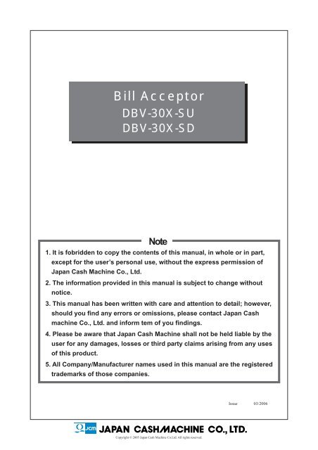
<strong>Bill</strong> <strong>Acceptor</strong><br />
DBV-30X-SU<br />
DBV-30X-SD<br />
Note<br />
1. It is fobridden to copy the contents of this manual, in whole or in part,<br />
except for the user’s personal use, without the express permission of<br />
Japan Cash Machine Co., Ltd.<br />
2. The information provided in this manual is subject to change without<br />
notice.<br />
3. This manual has been written with care and attention to detail; however,<br />
should you find any errors or omissions, please contact Japan Cash<br />
machine Co., Ltd. and inform tem of you findings.<br />
4. Please be aware that Japan Cash Machine shall not be held liable by the<br />
user for any damages, losses or third party claims arising from any uses<br />
of this product.<br />
5. All Company/Manufacturer names used in this manual are the registered<br />
trademarks of those companies.<br />
Issue 03/2006<br />
Copyright © 2005 Japan Cash Machine Co.Ltd. All rights reserved.
Preface/Documentation Conventions etc.<br />
Preface<br />
Thank you for purchasing the Japan Cash Machine <strong>Bill</strong> Accepter DBV-30X-SU/DBV-30X-SD (here after<br />
referred to as the “DBV-30X unit”). Please read this manual carefully as it explains, step by step, how to<br />
use the DBV-30X correctly and safely. Be sure to read this manual and any related materials thoroughly<br />
to understand the correct operation and functions of this unit.<br />
Documentation Conventions<br />
The list below describes the documentation convertions used in this manual.<br />
This icon indicates situations where slight bodily injury or equipment<br />
damage can occur.<br />
This icon indecates important information or procedures that must be<br />
followed for correct and risk-free unit operation.<br />
This icon indicates useful or recommended supplemental<br />
information.<br />
1), 2)<br />
This indicates steps in a procedure. Be sure to perform these steps in<br />
the order given.<br />
* This indicates useful or important supplemental information<br />
CE Marking Notes<br />
The DBV-301-SU is CE marked products.<br />
•Complies with the following Standard.<br />
EN61000-6-1: 2001 EN61000-4-2: 1995+A1 : 1998+A2 : 2001<br />
EN61000-4-3 : 2002+A1 : 2002<br />
EN61000-6-3 : 2001 EN55022 : 1998 (ClassB)<br />
2
Package Contents/Version Information<br />
Package Contents<br />
The DBV-30X unit’s packing box contains theitems listed below. Please check to confirm that all items<br />
shown below have been included.<br />
•DBV-30X-SX unit (1) •Harness (1)<br />
MDB Harness (EDP#: 128233) or<br />
Optional Harness (EDP#: 108233)<br />
MDB Harness<br />
Optional Harness<br />
Model and Serial No. Information<br />
To identify your DBV-30X unit’s model and serial number, see the metallic label attached to the left side<br />
of DBV-30X unit.<br />
MODEL DBV-301-SU-USA2-2111-D3<br />
SERIAL NO.* * * * * * * * * *<br />
DC 24-36V 0.9-0.6A<br />
MADE IN JAPAN<br />
3
Table of Contents<br />
Table of Contents<br />
CHAPTER 1<br />
Model Numbers and Specifications<br />
1-1. Precautions .............................................................................. 1-2<br />
1-2. Main Features........................................................................... 1-3<br />
1-2-1. Intelligent 3-way LED for Easy field Diagnosis .................................1-3<br />
1-2-2. Palm Programmable............................................................................1-3<br />
1-2-3. Built in Auditing Functions.................................................................1-3<br />
1-2-4. Optional <strong>Bill</strong> Recycler (RC-10) ...........................................................1-3<br />
1-3. DBV-30X Naming Composition ............................................... 1-4<br />
1-3-1. Model ....................................................................................................1-4<br />
1-3-2. Type ......................................................................................................1-4<br />
1-4. Component Names .................................................................. 1-5<br />
1-5. System Configuration.............................................................. 1-6<br />
1-5-1. DBV-301 System Configuration..........................................................1-6<br />
1-5-1. DBV-302 System Configuration..........................................................1-7<br />
1-6. Specifications .......................................................................... 1-8<br />
1-6-1. Technical Specifications .....................................................................1-8<br />
1-6-2. Environmental Specifications ............................................................1-8<br />
1-6-3. Electrical Specifications .....................................................................1-9<br />
1-6-4. Structural Specifications ....................................................................1-9<br />
1-7. Interface Connector and Pin Assignment............................ 1-10<br />
1-7-1. When using ID-0D3 Interface ............................................................1-10<br />
1-7-2. When using ID-003 Interface ............................................................1-12<br />
1-8. DIP Switch Settings ............................................................... 1-14<br />
1-8-1. DIP Switch 1 (SW1)............................................................................ 1-14<br />
1-8-2. DIP Switch 2 (SW2)............................................................................ 1-15<br />
1-9. Dimensions ............................................................................ 1-16<br />
1-9-1. DBV-30X-SU with 200 notes cash box ............................................. 1-16<br />
1-9-2. DBV-30X-SU with 300 notes cash box ............................................. 1-17<br />
1-9-3. DBV-30X-SU with 1,000 notes cash box .......................................... 1-18<br />
1-9-4. DBV-30X-SD with 200 notes cash box ............................................. 1-19<br />
1-9-5. DBV-30X-SD with 300 notes cash box ............................................. 1-20<br />
1-9-6. DBV-30X-SD with 1,000 notes cash box .......................................... 1-21<br />
4
Table of Contents<br />
CHAPTER 2<br />
Installation and Operation<br />
2-1. Installation ................................................................................ 2-2<br />
2-1-1. Installation ...........................................................................................2-2<br />
2-1-2. Changing the bill guides .....................................................................2-3<br />
2-1-3. Installing the Snack Mask ...................................................................2-4<br />
2-1-4. Installing the SD Module & SD Bracket ............................................. 2-6<br />
2-2. Operation Flowchart ................................................................ 2-4<br />
2-3. Collecting bills ......................................................................... 2-5<br />
2-4. Clearing <strong>Bill</strong> Jam...................................................................... 2-6<br />
2-4-1. When a bill jammed in Transport path............................................... 2-6<br />
2-4-2. When a bill jammed in <strong>Acceptor</strong> Head .............................................. 2-6<br />
2-5. Preventive Maintenance ......................................................... 2-7<br />
2-6. Technical Support ................................................................... 2-8<br />
CHAPTER 3<br />
Disassembly Instruction<br />
3-1. How to Remove CPU/Power Supply Board ........................... 3-2<br />
3-1-1. Removing the CPU/Power Sppuly board ..........................................3-2<br />
3-2-1. Removing the timing belts..................................................................3-5<br />
3-2. Disassembly of Pusher Mechanism Assembly ..................... 3-5<br />
3-2-2. Removing the Feed motor and stacker motor .................................. 3-7<br />
3-3-1. Removing the Sensor board ..............................................................3-9<br />
3-3-2. Removing the O-rings .......................................................................3-10<br />
3-3-3. Removing the Feed Small Boards ................................................... 3-12<br />
3-4. Disassembly of Down Guide................................................. 3-13<br />
3-4-1. Removing the MAG board ................................................................ 3-13<br />
CHAPTER 4<br />
Trouble Shooting and Diagnostics<br />
4-1. Error Code & Reject Code ....................................................... 4-2<br />
4-1-1. Error Codes ......................................................................................... 4-2<br />
4-1-2. Reject Codes........................................................................................ 4-3<br />
4-2. Trouble Shooting ..................................................................... 4-4<br />
4-2-1. General Problems................................................................................4-4<br />
4-2-2. Adjustment Problems .........................................................................4-5<br />
4-2-3. Communication Problems ..................................................................4-6<br />
5
Table of Contents<br />
4-3. Diagnostics .............................................................................. 4-7<br />
4-3-1. How to enter the Test Mode ................................................................4-7<br />
4-3-2. Feed Motor Forward/Reverse Rotation Test .....................................4-7<br />
4-3-3. Stacker Test .........................................................................................4-8<br />
4-3-4. Running Test........................................................................................4-9<br />
4-3-5. Continuous Insertion Protect Lever Test ........................................ 4-10<br />
4-3-6. <strong>Acceptor</strong> Sensor Test........................................................................4-10<br />
4-3-7. Stacker Sensor Test .......................................................................... 4-11<br />
4-3-8. <strong>Bill</strong> Acceptance Test ..........................................................................4-12<br />
4-3-9. Stacker Motor Forward/Reverse Rotation Test ...............................4-13<br />
4-3-10. DIP Switch Test................................................................................4-14<br />
4-4. Sensor, board and motor location........................................ 4-15<br />
4-5. Cable Diagram........................................................................ 4-16<br />
4-5-1. DBV-301 Cable Diagram....................................................................4-16<br />
4-5-2. DBV-302 Cable Diagram....................................................................4-17<br />
CHAPTER 5<br />
Software Download and Adjustment<br />
5-1. Software Download................................................................. 5-2<br />
5-1-1. Tools Required ....................................................................................5-2<br />
5-1-2. Initial Setting ........................................................................................5-2<br />
5-1-3. Starting Dwonload Program ...............................................................5-3<br />
5-2. Adjustment .............................................................................. 5-6<br />
5-2-1. Tools Required ....................................................................................5-6<br />
5-2-2. Installing the Adjustment Program (Cab300.exe) .............................5-6<br />
5-2-3. Initial Setting ........................................................................................5-6<br />
5-2-4. Adjustment Procedure ........................................................................5-7<br />
5-3. Using Palm ............................................................................ 5-13<br />
5-3-1. Items required ................................................................................... 5-13<br />
5-3-2. Installing File Conversion Program (PdbConvEn.CAB)................. 5-13<br />
5-3-3. Initial Setting required ......................................................................5-13<br />
5-3-4. Program Overview ............................................................................ 5-14<br />
5-3-5. Download the software program from Palm ................................... 5-15<br />
5-3-6. Getting the DBV-301 unit’s setting information .............................. 5-19<br />
5-3-7. Execute the Diagnostics ...................................................................5-20<br />
5-3-8. Get the Accepting Log from DBV-30X unit ......................................5-21<br />
5-3-9. Convert the Acceptance log data into the CSV format .................. 5-24<br />
6
Table of Contents<br />
CHAPTER 6<br />
Exploded View & Parts List<br />
6-1. Entire Unit............................................................................... 6-2<br />
6-1-1. Entire Unit Exploded View ................................................................. 6-2<br />
6-1-2. Entire Unit Parts List ........................................................................... 6-3<br />
6-2. Frame and Up/Down Guide .................................................... 6-4<br />
6-2-1. Frame and Up/Down Guide Exploded View .....................................6-4<br />
6-2-2. Frame and Up/Down Guide Parts List ............................................... 6-5<br />
6-3-1. Pusher Mechanism Exploded View ..................................................6-6<br />
6-3. Pusher Mechanism Assembly .............................................. 6-6<br />
6-3-2. Pusher Mechanism Parts List ............................................................6-7<br />
6-4. Cashbox Unit.......................................................................... 6-8<br />
6-4-1. 200 note cashbox Exploded View ..................................................... 6-8<br />
6-4-2. 200 note cashbox Parts List ............................................................... 6-9<br />
6-4-1. 300 note cashbox Exploded View ................................................... 6-10<br />
6-4-2. 300 notes cashbox Parts List ........................................................... 6-11<br />
6-5-1. 1,000 note cashbox Exploded View ................................................ 6-12<br />
6-5-2. 1,000 notes cashbox Parts List ........................................................ 6-13<br />
6-5. SD Module<br />
6-5-1. SD Module Exploded View<br />
6-5-2. SD Module Parts List<br />
6-6. Snack Mask<br />
6-6-1. Snack Mask Exploded View<br />
6-6-2. Snack Mask Parts List<br />
CHAPTER 7<br />
Optional <strong>Bill</strong> Recycler Unit (RC-10)<br />
7-1. Precautions .............................................................................. 7-2<br />
7-2. RC-10 Component Names ....................................................... 7-3<br />
7-3. Specifications .......................................................................... 7-4<br />
7-3-1. Technical Specifications ..................................................................... 7-4<br />
7-3-2. Environmental Specifications ............................................................7-4<br />
7-3-4. DIP Switch Settings.............................................................................7-5<br />
7
Table of Contents<br />
7-6. Installation and Operation....................................................... 7-8<br />
7-6-1. Installing/Removing the RC-10 unit ...................................................7-8<br />
7-6-2. Installing/Removing the Cash Box ....................................................7-9<br />
7-6-3. Autoloading <strong>Bill</strong>s ...............................................................................7-10<br />
7-6-4. Stacking <strong>Bill</strong>s ..................................................................................... 7-11<br />
7-6-5. Dispensing <strong>Bill</strong> .................................................................................. 7-12<br />
7-6-6. Clearing JAM <strong>Bill</strong> ...............................................................................7-13<br />
7-7. Diagnostic Code and Wiring Diagram.................................. 7-15<br />
7-7-1. LED Diagnostic Codes ......................................................................7-15<br />
7-7-2. Wiring Diagram ..................................................................................7-16<br />
7-8. Disassembly Instruction ....................................................... 7-17<br />
7-8-1. Removing Side Cover .......................................................................7-17<br />
7-8-2. Changing Recycle Board ..................................................................7-18<br />
7-8-3. Changing PT Board/LED Board .......................................................7-19<br />
7-8-5. Changing Encoder Board ................................................................. 7-21<br />
7-9. Exploded View and Parts List ............................................... 7-22<br />
7-9-1 Exploded View ................................................................................... 7-22<br />
7-9-2. RC-10 Parts List................................................................................. 7-23<br />
8
<strong>Bill</strong> <strong>Acceptor</strong><br />
DBV-30X Service Manual<br />
Chapter 1<br />
Model Numbers<br />
& Specifications<br />
1-1. Precautions<br />
1-2. Main Features<br />
1-3. DBV-30X Naming Composition<br />
1-4. Component Names<br />
1-5. System Configuration<br />
1-6. Specifications<br />
1-7. Interface Connector and Pin Assignment<br />
1-8. DIP Switches Settings<br />
1-9. Dimensions<br />
Issue 08/2007
DBV-30X Service Manual<br />
1-1. Precautions<br />
CHAPTER<br />
1<br />
- Do not insert a torn, folded, or wet bill, as this may cause bill jam inside the unit.<br />
- Do not expose the unit to water. The unit contains several precision electronic devices<br />
which can be damaged if water or any liquid is sprayed or spilled into the unit.<br />
- Do not install the unit in a dusty environment. Dust may affect the sensor performance.<br />
- When installing the unit, be sure to turn the power OFF.<br />
- When installing the DBV-30X unit, tighten mounting nuts until snug. DO NOT overtighten.<br />
- To avoid the electrical hazards and equipment damage, be sure to use only specified<br />
voltage.<br />
1-2<br />
© 2006 Japan Cash Machine Co.Ltd. All rights reserved.
DBV-30X Service Manual<br />
1-2. Main Features<br />
The DBV-30X has the following features.<br />
1-2-1. Intelligent 3-way LED for Easy<br />
field Diagnosis<br />
DBV-30X unit has intelligent 3-way LED. It<br />
blinks depending on the error. Color of LED<br />
and the number of blinking shows the error<br />
type.<br />
1<br />
CHAPTER<br />
1-2-2. Palm Programmable<br />
Palm can be connected to DBV-30X unit to<br />
download the software program, execute the<br />
diagnostic test and get the acceptance log<br />
data. For details about connecting to Palm,<br />
refer to 5-3. Using Palm.<br />
1-2-3. Built in Auditing Functions<br />
DBV-30X unit has the following built-in<br />
functions.<br />
- Jam Rate<br />
- Acceptance Rate<br />
- Internal Diagnostics<br />
- Money Auditing<br />
1-2-4. Optional <strong>Bill</strong> Recycler (RC-10)<br />
DBV-301-SU unit can attach an optional bill<br />
recycler unit (RC-10). It is the first bill<br />
acceptor for the vending industry with built-in<br />
intelligence for recycling of notes.<br />
© 2006 Japan Cash Machine Co.Ltd. All rights reserved.<br />
1-3
DBV-30X Service Manual<br />
1-3. DBV-30X Naming Composition<br />
CHAPTER<br />
1<br />
1-3-1. Model<br />
DBV - 3 0 1 - SU<br />
(1) (2) (3) (4) (5)<br />
(1) Model Name<br />
(2) Series Name<br />
(3) CPU Board Type<br />
0: JCM Standard<br />
(4) Power supply<br />
0: DC12V<br />
1: DC24V<br />
2: AC117V<br />
(5) Stacker Type<br />
SU: Upward vertical stacking<br />
SD: Downward vertical stacking<br />
1-3-2. Type<br />
* * * - * * * * * - **<br />
(6) (7) (8) (9) (10) (11) (12)<br />
(6) Country Code *1<br />
3-digit ISO code<br />
Ex RUS - Russia<br />
(7) Cash Box Capacity<br />
2: 200 Notes Cash Box<br />
3: 300 Notes Cash Box<br />
5: 500 Notes Cash Box<br />
A: 1000 Notes Cash Box<br />
(8) Bezel Type<br />
1: JCM Standard Bezel (SU/SD)<br />
2: Snack Mask (SU/SD)<br />
3: Euro Bezel (SU)<br />
4: Euro Bezel (SD)<br />
1-4<br />
© 2006 Japan Cash Machine Co.Ltd. All rights reserved.
DBV-30X Service Manual<br />
(9) Guide Width<br />
1: 67 mm<br />
3: 71 mm<br />
4: 73mm<br />
(10)Cash Box Type<br />
1: Upward bill ejection box<br />
1<br />
CHAPTER<br />
(11)Recycle Type (Optional)<br />
0: without bill recycler unit<br />
1: with bill recycler unit<br />
(12)Interface Type *1<br />
D3: ID-0D3 (MDB interface)<br />
03: ID-003 (Serial interface)<br />
44: ID-044 (OEM interface)<br />
*1 For another interface, please contact JCM.<br />
© 2006 Japan Cash Machine Co.Ltd. All rights reserved.<br />
1-5
DBV-30X Service Manual<br />
1-4. Component Names<br />
CHAPTER<br />
1<br />
Cash box cover<br />
Cash box release lever<br />
RC-10<br />
Connecotr<br />
Cash box<br />
Faceplate<br />
Communication Port<br />
Indication LED<br />
AC117V<br />
Power Supply<br />
Connector<br />
(For DBV-302 Only)<br />
DIP Switch 1<br />
Interface<br />
Connector<br />
<strong>Acceptor</strong> head<br />
DIP Switch 2<br />
Condition LED<br />
<strong>Acceptor</strong> head<br />
release lever<br />
1-6<br />
© 2006 Japan Cash Machine Co.Ltd. All rights reserved.
DBV-30X Service Manual<br />
1-5. System Configuration<br />
1-5-2. DBV-300 System Configuration<br />
CHAPTER<br />
1<br />
DBV-300<br />
Interface Connector<br />
Communication Port<br />
Harness<br />
(EDP# 116490, Part# 3280-03-15)<br />
Palm (R) Tungsten C *1<br />
(EDP# G00171)<br />
Download Adapter<br />
PC<br />
(OS: Windows (R) 98 SE/2000) *2<br />
JCM Power Supply Unit<br />
(EDP# 116477, Part# VM300)<br />
Host Machine<br />
Optional Harness<br />
(EDP# 108233, Part# 3210-05-05B)<br />
*1 Palm can be connected to download a software, perform the diagnostics and<br />
collect the accepting log data.<br />
*2 PC can be connected to download software and perform an adjustment. For<br />
details about software downloading and adjustment, refer to Chapter 5.<br />
© 2006 Japan Cash Machine Co.Ltd. All rights reserved.<br />
1-7
DBV-30X Service Manual<br />
1-5-2. DBV-301 System Configuration<br />
CHAPTER<br />
1<br />
DBV-301<br />
Interface Connector<br />
Communication Port<br />
RC-10 Connector<br />
Optional <strong>Bill</strong> Recycler Unit<br />
(RC-10) *1<br />
JCM’ s<br />
OPTIPAY CC *2<br />
Palm (R) Tungsten C *3<br />
Harness<br />
(EDP# 116490, Part# 3280-03-15)<br />
Download Adapter<br />
(EDP# G00171)<br />
PC<br />
(OS: Windows (R) 98 SE/2000) *4<br />
JCM Power Supply Unit<br />
(EDP# 116480, Part# VM301)<br />
or<br />
Host Machine<br />
Optional Harness<br />
(EDP# 108233, Part# 3210-05-05B)<br />
Serial/Paluse<br />
MDB Harness<br />
(EDP# 118761, Part# 3210-05-03A)<br />
MDB<br />
*1 The optional bill recycler unit (RC-10) can be installed with only DBV-301 unit<br />
which is using MDB interface, and which is connecting with JCM’s Coin Changer<br />
(OPTIPAY CC). For details about RC-10 unit, refer to Chapter 7.<br />
*2 For details about JCM’s Coin Changer (OPTIPAY CC), please contact JCM.<br />
*3 Palm can be connected to download a software, perform the diagnostics and<br />
collect the accepting log data.<br />
*4 PC can be connected to download software and perform an adjustment. For<br />
details about software downloading and adjustment, refer to Chapter 5.<br />
1-8<br />
© 2006 Japan Cash Machine Co.Ltd. All rights reserved.
DBV-30X Service Manual<br />
1-5-3. DBV-302 System Configuration<br />
CHAPTER<br />
1<br />
DBV-302<br />
Interface Connector<br />
Communication Port<br />
Harness<br />
(EDP# 116490, Part# 3280-03-15)<br />
Palm (R) Tungsten C *1<br />
(EDP# G00171)<br />
Download Adapter<br />
PC<br />
(OS: Windows (R) 98 SE/2000) *2<br />
Host Machine<br />
Optional Harness<br />
(EDP# 108233, Part# 3210-05-05B)<br />
*1 Palm can be connected to download a software, perform the diagnostics and<br />
collect the accepting log data.<br />
*2 PC can be connected to download software and perform an adjustment. For<br />
details about software downloading and adjustment, refer to Chapter 5.<br />
© 2006 Japan Cash Machine Co.Ltd. All rights reserved.<br />
1-9
DBV-30X Service Manual<br />
1-6. Specifications<br />
CHAPTER<br />
1<br />
1-6-1. Technical Specifications<br />
<strong>Bill</strong> Accepted<br />
Insertion Direction<br />
Acceptance Rate<br />
Processing Speed<br />
Cash Box Capacity<br />
Interface<br />
Escrow<br />
LED<br />
Width (min. 65 - max. 72 mm) *1<br />
Length (min. 120 - max. 160 mm)<br />
Refer to the software Information Sheet<br />
Refer to the software Information Sheet<br />
Approx. 2 seconds (from bill insertion to credit signal output)<br />
Approx. 3 seconds (from bill insertion to bill stack completion)<br />
200 Notes Cash Box<br />
300 Notes Cash Box<br />
500 Notes Cash Box<br />
1,000 Notes Cash Box<br />
Pulse/MDB *2/Serial<br />
1 <strong>Bill</strong><br />
Condition LED (Red/Yellow/Green) (Rear)<br />
Indication LED (Green) (Front)<br />
*1 <strong>Bill</strong>s narrower than 65 mm (width) or wider than 71mm (width) will need special<br />
bill guides. Contact your JCM sales representative for details.<br />
*2 When using MDB interface, the optional bill recycler unit (RC-10) can be attached.<br />
For details about RC-10 unit, refer to Chapter 7.<br />
1-6-2. Environmental Specifications<br />
Operation Temperature *1<br />
Storage Temperature<br />
Operation Humidity *1<br />
Storage Temperature<br />
Light disturbance<br />
Installation<br />
-15 o C to 60 o C<br />
-20 o C to 60 o C<br />
+15% to 95%RH (no condensing)<br />
+15% to 95%RH (no condensing)<br />
Direct sunlight shall be avoided<br />
Indoor and Outdoor<br />
(not exposed to wind and weather)<br />
*1 Be sure to satisfy the following temperature humidity conditions.<br />
Additional Range<br />
Range of operation<br />
temperature/humidity<br />
Additional Range<br />
1-10<br />
© 2006 Japan Cash Machine Co.Ltd. All rights reserved.
DBV-30X Service Manual<br />
1-6-3. Electrical Specifications<br />
Power Supply<br />
Power Consumption<br />
1-6-4. Structural Specifications<br />
Mounting<br />
Weight<br />
Outline Dimentions<br />
DBV-300 DBV-301 DBV-302<br />
DC12V (+5%)<br />
DC24V (+5% )<br />
AC117V<br />
2.5A (Recommended) 2.5A (Recommended) AC90V to AC123V<br />
(50/60Hz)<br />
Standby: 0.3A<br />
In Operation: 0.6A<br />
(Max: 1.5A)<br />
Standby: 0.2A<br />
In Operation: 0.4A<br />
(Max: 0.9A)<br />
Holizontal Mounting<br />
Approx. 1.2kg (with 200 Note Cash Box)<br />
Refer to 1-9. Dimensions<br />
Standby: 0.07A<br />
In Operation: 0.16A<br />
(Max: 0.45A)<br />
1<br />
CHAPTER<br />
© 2006 Japan Cash Machine Co.Ltd. All rights reserved.<br />
1-11
DBV-30X Service Manual<br />
1-7. Interface Connector and Pin Assignment<br />
CHAPTER<br />
1<br />
1 2<br />
3 4<br />
5 6<br />
7 8<br />
9 10<br />
11 12<br />
13 14<br />
15 16<br />
17 18<br />
Header(Dual Light Angle Type): 702290-3007 (US MOLEX)<br />
Recommended Housing: 70066-0113 (US MOLEX)<br />
Clip (Dual Type): 70013-0018 (US MOLEX)<br />
Terminal: 70058-0204 (US MOLEX)<br />
Recommended Wire: String AWG#24 to 26<br />
1-7-1. When using ID-0D3 (MDB) Interface<br />
•DBV-301<br />
Pin No. Signal Name I/O *1 Function<br />
1 VDD1 DC24V<br />
2 VSS1 GND<br />
3 NC Not Connected<br />
4 NC Not Connected<br />
5 TXD2 OUT Photo-coupler: Output Signal Line from <strong>Bill</strong> <strong>Acceptor</strong><br />
6 RXD2 IN Photo-coupler: Input Signal Line from <strong>Bill</strong> <strong>Acceptor</strong><br />
7 SG2 Photo-coupler: Signal Ground<br />
8 NC Not Connected<br />
9 NC Not Connected<br />
10 NC Not Connected<br />
11 NC Not Connected<br />
12 NC Not Connected<br />
13 NC Not Connected<br />
14 NC Not Connected<br />
15 NC Not Connected<br />
16 NC Not Connected<br />
17 NC Not Connected<br />
18 NC Not Connected<br />
*1 I/O (input/output) is the term from bill acceptor’s side.<br />
1-12<br />
© 2006 Japan Cash Machine Co.Ltd. All rights reserved.
DBV-30X Service Manual<br />
Photo Coupler-isoration Input/Output Circuit<br />
ACCEPTOR<br />
HOST CONTROLLER<br />
CHAPTER<br />
1<br />
© 2006 Japan Cash Machine Co.Ltd. All rights reserved.<br />
1-13
DBV-30X Service Manual<br />
CHAPTER<br />
1<br />
1-7-2. When using ID-003 (Serial) Interface<br />
•DBV-301<br />
Pin No. Signal Name I/O *1 Function<br />
1 VDD1 DC24V *2<br />
2 VSS1 DC24V GND *2<br />
3 NC Not Connected<br />
4 NC Not Connected<br />
5 TXD2 OUT Photo-coupler: Output Signal Line from <strong>Bill</strong> <strong>Acceptor</strong> *3<br />
6 RXD2 IN Photo-coupler: Input Signal Line from <strong>Bill</strong> <strong>Acceptor</strong> *3<br />
7 SG2 Photo-coupler: Signal Ground *3<br />
8 TXD1 OUT RS-232C: Output Signal Line from <strong>Bill</strong> <strong>Acceptor</strong> *3<br />
9 RXD1 IN RS-232C: Input Signal Line from <strong>Bill</strong> <strong>Acceptor</strong> *3<br />
10 SG RS-232C/TTL: Signal Ground *3<br />
11 TXD0 OUT TTL: Output Signal Line from <strong>Bill</strong> <strong>Acceptor</strong> *3<br />
12 RXD0 IN TTL: Input Signal Line from <strong>Bill</strong> <strong>Acceptor</strong> *3<br />
13 NC Not Connected<br />
14 NC Not Connected<br />
15 NC Not Connected<br />
16 NC Not Connected<br />
17 NC Not Connected<br />
18 NC Not Connected<br />
*1 I/O (input/output) is the term from bill acceptor’s side.<br />
*2 To avoid the electrical hazards and equipment damage, be sure to use only specified<br />
voltage.<br />
*3 The serial I/F level (Photo-coupler/RS-232C/TTL) can be selected with DIP Switch<br />
2. For details, refer to 1-8. DIP Switch Setting.<br />
•DBV-302<br />
Pin No. Signal Name I/O *1 Function<br />
1 NC Not Connected<br />
2 NC Not Connected<br />
3 NC Not Connected<br />
4 NC Not Connected<br />
5 TXD2 OUT Photo-coupler: Output Signal Line from <strong>Bill</strong> <strong>Acceptor</strong> *2<br />
6 RXD2 IN Photo-coupler: Input Signal Line from <strong>Bill</strong> <strong>Acceptor</strong> *2<br />
7 SG2 Photo-coupler: Signal Ground *2<br />
8 TXD1 OUT RS-232C: Output Signal Line from <strong>Bill</strong> <strong>Acceptor</strong> *2<br />
9 RXD1 IN RS-232C: Input Signal Line from <strong>Bill</strong> <strong>Acceptor</strong> *2<br />
10 SG RS-232C/TTL: Signal Ground *2<br />
11 TXD0 OUT TTL: Output Signal Line from <strong>Bill</strong> <strong>Acceptor</strong> *2<br />
12 RXD0 IN TTL: Input Signal Line from <strong>Bill</strong> <strong>Acceptor</strong> *2<br />
13 NC Not Connected<br />
14 NC Not Connected<br />
15 NC Not Connected<br />
16 NC Not Connected<br />
17 NC Not Connected<br />
18 NC Not Connected<br />
*1 I/O (input/output) is the term from bill acceptor’s side.<br />
*2 The serial I/F level (Photo-coupler/RS-232C/TTL) can be selected with DIP Switch<br />
2. For details, refer to 1-8. DIP Switch Setting.<br />
1-14<br />
© 2006 Japan Cash Machine Co.Ltd. All rights reserved.
DBV-30X Service Manual<br />
Photo-coupler isolation Input/Output Circuit<br />
ACCEPTOR<br />
HOST CONTROLLER<br />
CHAPTER<br />
1<br />
RS-232C Input/Output Circuit<br />
ACCEPTOR<br />
HOST CONTROLLER<br />
TTL Input/Output Circuit<br />
ACCEPTOR<br />
HOST CONTROLLER<br />
© 2006 Japan Cash Machine Co.Ltd. All rights reserved.<br />
1-15
DBV-30X Service Manual<br />
CHAPTER<br />
1<br />
1-7-3. When using ID-002 (Pulse) Interface<br />
•DBV-300<br />
Pin No. Signal Name I/O *1 Function Active<br />
1 NC Not Connected<br />
2 NC Not Connected<br />
3 VDD1 DC12V<br />
4 VSS1 DC12V GND<br />
5 NC Not Connected<br />
6 NC Not Connected<br />
7 NC Not Connected<br />
8 NC Not Connected<br />
9 NC Not Connected<br />
10 SG Signal Ground<br />
11 /VEND OUT Accepted denomination Signal Lo<br />
12 NC Not Connected<br />
13 NC Not Connected<br />
14 /ENABLE IN <strong>Bill</strong> Inhibit (Hi) / Accept (Lo) Signal Lo<br />
15 NC Not Connected<br />
16 /BUSY OUT <strong>Acceptor</strong> Operating Signal Lo<br />
17 /ABN OUT <strong>Acceptor</strong> Error Signal Lo<br />
18 /FULL OUT Cash Box Full signal Lo<br />
*1 I/O (input/output) is the term from bill acceptor’s side.<br />
•DBV-301<br />
Pin No. Signal Name I/O *1 Function Active<br />
1 VDD1 DC24V<br />
2 VSS1 DC24V GND<br />
3 NC Not Connected<br />
4 NC Not Connected<br />
5 NC Not Connected<br />
6 NC Not Connected<br />
7 NC Not Connected<br />
8 NC Not Connected<br />
9 NC Not Connected<br />
10 SG Signal Ground<br />
11 /VEND OUT Accepted denomination Signal Lo<br />
12 NC Not Connected<br />
13 NC Not Connected<br />
14 /ENABLE IN <strong>Bill</strong> Inhibit (Hi) / Accept (Lo) Signal Lo<br />
15 NC Not Connected<br />
16 /BUSY OUT <strong>Acceptor</strong> Operating Signal Lo<br />
17 /ABN OUT <strong>Acceptor</strong> Error Signal Lo<br />
18 /FULL OUT Cash Box Full signal Lo<br />
*1 I/O (input/output) is the term from bill acceptor’s side.<br />
1-16<br />
© 2006 Japan Cash Machine Co.Ltd. All rights reserved.
DBV-30X Service Manual<br />
•Sequence Chart<br />
Accept <strong>Bill</strong><br />
DISABLE/<br />
ENABLE<br />
BUSY<br />
1<br />
CHAPTER<br />
VEND<br />
ABN<br />
FULL<br />
DISABLE<br />
DRAWING BILL<br />
and VALIDATION<br />
STACKING<br />
VEND<br />
OUTPUT<br />
STAND BY<br />
INSERT BILL<br />
STAND BY<br />
Return <strong>Bill</strong><br />
DISABLE/<br />
ENABLE<br />
BUSY<br />
VEND<br />
ABN<br />
FULL<br />
DISABLE<br />
DRAWING BILL<br />
and VALIDATION<br />
RETRUN BILL<br />
DISABLE(INHIBIT)<br />
INSERT BILL<br />
STAND BY<br />
© 2006 Japan Cash Machine Co.Ltd. All rights reserved.<br />
1-17
DBV-30X Service Manual<br />
Stack <strong>Bill</strong><br />
DISABLE/<br />
ENABLE<br />
CHAPTER<br />
1<br />
BUSY<br />
VEND<br />
ABN<br />
FULL<br />
DISABLE<br />
DRAWING BILL<br />
and VALIDATION<br />
STACKING<br />
VEND<br />
OUTPUT<br />
STACKER FULL<br />
INSERT BILL<br />
STAND BY<br />
Jam <strong>Bill</strong><br />
DISABLE/<br />
ENABLE<br />
BUSY<br />
VEND<br />
ABN<br />
FULL<br />
DISABLE<br />
DRAWING BILL<br />
and VALIDATION<br />
REJECT<br />
BILL<br />
JAMMED BILL<br />
STAND BY<br />
INSERT BILL<br />
STAND BY<br />
REMOVED BILL<br />
1-18<br />
© 2006 Japan Cash Machine Co.Ltd. All rights reserved.
DBV-30X Service Manual<br />
1-8. DIP Switch Settings<br />
DBV-30X unit have 2 DIP Switches (SW 1/SW 2). They are located on the left side of<br />
DBV-30X unit. Verify the DIP switch settings before installing the DBV-30X unit. The DIP<br />
switch settings are determined by the software. See software specifications provided separately<br />
for DIP switch settings of your software.<br />
8<br />
1<br />
CHAPTER<br />
OFF<br />
1<br />
5<br />
5<br />
4<br />
2<br />
3<br />
6<br />
7<br />
8<br />
OFF<br />
1<br />
2<br />
3<br />
4<br />
6<br />
7<br />
DIP Swich 1<br />
DIP Swich 2<br />
1-8-1. DIP Switch 1 (SW1)<br />
SW 1 sets the accepted Denomination and mode. Depending on the software, the denomination<br />
settings will differ. Refer to the software specifications.<br />
No. Function ON OFF<br />
SW1-1 Denomination 1<br />
SW1-2 Denomination 2<br />
SW1-3 Denomination 3<br />
SW1-4 Denomination 4 Inhibit<br />
Accept<br />
SW1-5 Denomination 5<br />
SW1-6 Denomination 6<br />
SW1-7 Denomination 7<br />
SW1-8 Mode Setting Test Mode *1 Normal Mode<br />
*1 For details about Test Mode, refer to 4-3. Diagnostics.<br />
© 2006 Japan Cash Machine Co.Ltd. All rights reserved.<br />
1-19
DBV-30X Service Manual<br />
1-8-2. DIP Switch 2 (SW2)<br />
DIP Switch 2 sets the Communication method. For details, refer to the software specifications.<br />
CHAPTER<br />
1<br />
ID-0D3 (MDB) interface<br />
No. Function ON OFF<br />
SW2-1 -<br />
SW2-2 -<br />
SW2-3 -<br />
SW2-4 -<br />
SW2-5 -<br />
Always OFF<br />
SW2-6 -<br />
SW2-7 -<br />
SW2-8 -<br />
ID-002 (Pulse) interface<br />
No.<br />
Function<br />
SW2-1 SW2-2 PULSE WIDTH<br />
OFF OFF 50ms/300ms<br />
ON OFF 50ms/50ms<br />
OFF ON 80ms/120ms<br />
ON ON 150ms/180ms<br />
SW2-3 SW2-4 PULSE COUNT<br />
OFF OFF 1 Pulse<br />
ON OFF 4 Pulse<br />
OFF ON 10 Pulse<br />
ON ON 20 Pulse<br />
SW2-5 Always OFF -<br />
SW2-6 Always OFF -<br />
SW2-7 Always OFF -<br />
SW2-8 Always ON -<br />
ID-003 (Serial) interface<br />
No.<br />
Function<br />
SW2-1 SW2-2 Serial I/F Level<br />
OFF<br />
OFF<br />
Photo-coupler<br />
Isoration<br />
ON OFF TTL<br />
OFF ON RS-232C<br />
ON OFF RS-232C<br />
SW2-3 Always OFF -<br />
SW2-4 Always OFF -<br />
SW2-5 Always OFF -<br />
SW2-6 Always OFF -<br />
SW2-7 Always OFF -<br />
SW2-8 Always OFF -<br />
1-20<br />
© 2006 Japan Cash Machine Co.Ltd. All rights reserved.
DBV-30X Service Manual<br />
CHAPTER<br />
1<br />
1-9. Dimensions<br />
10.1<br />
22<br />
59.1 15.5<br />
10.5 (<strong>Bill</strong> Insertion Slot)<br />
+0.1<br />
116<br />
134.1<br />
4-5<br />
11.6<br />
59.7<br />
245.6<br />
174.3<br />
1-9-1. DBV-30X-SU with 200 Notes Cash Box<br />
88<br />
8.4<br />
2-5<br />
50.8 +0.1<br />
84 +0.1<br />
86<br />
98.2<br />
33<br />
41.5<br />
72<br />
113.5<br />
Unit : mm<br />
14.6 107<br />
4 18<br />
© 2006 Japan Cash Machine Co.Ltd. All rights reserved.<br />
1-21
DBV-30X Service Manual<br />
1-9-2. DBV-30X-SU with 300 Notes Cash Box<br />
88<br />
44<br />
2-5.4<br />
50.8<br />
CHAPTER<br />
1<br />
10.1<br />
22<br />
116 +0.1<br />
134.1<br />
86<br />
84<br />
33<br />
41.5<br />
72<br />
59.1<br />
14.6 107<br />
4 18<br />
15.5<br />
10.5 (<strong>Bill</strong> Insertion Slot)<br />
2-5.4<br />
11.6<br />
71.3<br />
249.6<br />
174.3<br />
178.3<br />
8.4<br />
98.2<br />
+0.1<br />
+0.1<br />
127<br />
Unit: mm<br />
1-22<br />
© 2006 Japan Cash Machine Co.Ltd. All rights reserved.
DBV-30X Service Manual<br />
1-9-3. DBV-30X-SU with 500 Notes Cash Box<br />
88 Unit: mm<br />
44<br />
2-5.4<br />
33<br />
41.5<br />
72<br />
153.5<br />
10.1<br />
14.6<br />
59.1<br />
15.5<br />
22 10.7 (<strong>Bill</strong> Insertion Slot)<br />
2-5.4<br />
116<br />
134.1<br />
107<br />
4 18<br />
11.6<br />
174.3<br />
71.3<br />
178.3<br />
249.6<br />
50.8 ±0.1<br />
84 ±0.1<br />
86<br />
8.4<br />
98.2<br />
CHAPTER<br />
1<br />
© 2006 Japan Cash Machine Co.Ltd. All rights reserved.<br />
1-23
DBV-30X Service Manual<br />
1-9-4. DBV-30X-SU with 1,000 Notes Cash Box<br />
88<br />
44<br />
86<br />
98.2<br />
CHAPTER<br />
1<br />
14.6<br />
4<br />
22<br />
59.1<br />
18<br />
134.1<br />
107<br />
15.5<br />
10.5 (<strong>Bill</strong> Insertion Slot)<br />
84 0.1<br />
33 72<br />
41.5<br />
10.1 116 0.1<br />
11.6<br />
179.3<br />
66.3 183.3<br />
249.6<br />
2-5.4<br />
50.8<br />
8.4<br />
250<br />
2-5.4<br />
0.1<br />
Unit : mm<br />
1-24<br />
© 2006 Japan Cash Machine Co.Ltd. All rights reserved.
DBV-30X Service Manual<br />
CHAPTER<br />
1<br />
1-9-5. DBV-30X-SD with 200 Notes Cash Box<br />
98.2<br />
86<br />
84<br />
<br />
2-5.4<br />
8.4<br />
33<br />
41.5<br />
72<br />
<br />
15.5<br />
134.1<br />
+0.1<br />
116 10.1<br />
107<br />
59.1<br />
18<br />
22<br />
4<br />
14.6<br />
174.3<br />
269.1<br />
11.6<br />
71.3<br />
+0.1<br />
+0.1<br />
2-5.4<br />
90<br />
113.5<br />
Unit : mm<br />
© 2006 Japan Cash Machine Co.Ltd. All rights reserved.<br />
1-25
DBV-30X Service Manual<br />
1-9-6. DBV-30X-SD with 300 Notes Cash Box<br />
98.2<br />
86<br />
84<br />
50.8<br />
2-5.4<br />
8.4<br />
<br />
<br />
<br />
CHAPTER<br />
1<br />
<br />
2-5.4<br />
15.5<br />
134.1<br />
+0.1<br />
116 10.1<br />
107<br />
59.1<br />
18<br />
22<br />
<br />
<br />
<br />
<br />
<br />
11.6<br />
<br />
+0.1<br />
+0.1<br />
90<br />
<br />
Unit: mm<br />
1-26<br />
© 2006 Japan Cash Machine Co.Ltd. All rights reserved.
DBV-30X Service Manual<br />
CHAPTER<br />
1<br />
1-9-7. DBV-30X-SD with 500 Notes Cash box and SD Bracket<br />
2-5.4<br />
10.7 (<strong>Bill</strong> Insertion Slot)<br />
15.5<br />
116 ±0.1 24.5<br />
61.6<br />
107 17.1<br />
18 4<br />
174.3<br />
178.3<br />
271.7<br />
14.1<br />
73.8<br />
103.2 5.9<br />
86<br />
84 ±0.1<br />
50.8 ±0.1<br />
2-5.4<br />
41.5 153.5<br />
33 72<br />
1.6<br />
Unit: mm<br />
12.6<br />
© 2006 Japan Cash Machine Co.Ltd. All rights reserved.<br />
1-27
DBV-30X Service Manual<br />
1-9-8. DBV-30X-SD with 1,000 Notes Cash Box and SD Bracket<br />
86<br />
<br />
50.8<br />
6-φ5.4<br />
33<br />
41.5<br />
72<br />
250<br />
CHAPTER<br />
1<br />
<br />
15.5<br />
<br />
107<br />
18<br />
17.1<br />
4<br />
183.3<br />
179.3<br />
107.2 3.9<br />
24.5<br />
12.6<br />
271.7<br />
14.1<br />
68.8<br />
0.1<br />
0.1<br />
1.6<br />
Unit : mm<br />
0.1<br />
61.6<br />
1-28<br />
© 2006 Japan Cash Machine Co.Ltd. All rights reserved.
DBV-30X Service Manual<br />
CHAPTER<br />
1<br />
1-9-9. DBV-30X-SD with 200 Notes Cash Box and Lock Module<br />
98.2<br />
84.7<br />
84<br />
8.4<br />
2-5.4<br />
9.5 (<strong>Bill</strong> Insertion Slot)<br />
15.5<br />
107.3<br />
59.1<br />
27<br />
14.2<br />
4.4<br />
269.1<br />
11.6<br />
71.3<br />
50.8<br />
2-5.4<br />
34.5<br />
13<br />
91.1<br />
134.1<br />
116<br />
22<br />
10.1<br />
174.3<br />
132.6<br />
85<br />
90<br />
19.6<br />
24.4<br />
137.6<br />
Unit: mm<br />
© 2006 Japan Cash Machine Co.Ltd. All rights reserved.<br />
1-29
DBV-30X Service Manual<br />
1-9-10. DBV-30X-SD with 300 Notes Cash Box and Lock Module<br />
98.2<br />
8.4<br />
84.7<br />
CHAPTER<br />
1<br />
2-5.4<br />
9.5 (<strong>Bill</strong> Insertion Slot)<br />
15.5<br />
107.3<br />
59.1<br />
27<br />
14.2<br />
4.4<br />
269.1<br />
11.6<br />
71.3<br />
84 ±0.1<br />
50.8 ±0.1<br />
2-5.4<br />
34.5<br />
13<br />
91.1<br />
134.1<br />
116 ±0.1<br />
22<br />
10.1<br />
174.3<br />
178.3<br />
146.1<br />
85<br />
90<br />
19.6<br />
24.4<br />
137.6<br />
Unit: mm<br />
1-30<br />
© 2006 Japan Cash Machine Co.Ltd. All rights reserved.
DBV-30X Service Manual<br />
CHAPTER<br />
1<br />
178.3<br />
1-9-11. DBV-30X-SD with 500 Note Cash Box, SD Bracket and Lock Module<br />
41.5 153.5<br />
33<br />
72<br />
1.6<br />
116 ±0.1<br />
2-5.4<br />
10.7 (<strong>Bill</strong> Insertion Slot) 24.5<br />
15.5<br />
61.6<br />
107<br />
17.1<br />
18 4<br />
174.3<br />
14.1<br />
12.6<br />
73.8<br />
303.1<br />
103.2 5.9<br />
86<br />
Unit: mm<br />
84 ±0.1<br />
50.8 ±0.1<br />
2-5.4<br />
© 2006 Japan Cash Machine Co.Ltd. All rights reserved.<br />
1-31
DBV-30X Service Manual<br />
1.6<br />
CHAPTER<br />
1<br />
183.3<br />
14.1<br />
68.8<br />
103.2<br />
±0.1<br />
±<br />
2-5.4<br />
5.9<br />
34.5<br />
13<br />
91.1<br />
269.1<br />
116 ±0.1<br />
107.3<br />
4-5.4<br />
61.6<br />
24.5<br />
14.2<br />
27 4.4<br />
271.7<br />
1-9-12. DBV-30X-SD with 1,000 Notes Cash Box, SD Bracket and Lock Module<br />
9.5 (<strong>Bill</strong> Insertion Slot)<br />
15.5<br />
12.6<br />
85<br />
90<br />
19.6<br />
24.4<br />
137.6<br />
Unit: mm<br />
1-32<br />
© 2006 Japan Cash Machine Co.Ltd. All rights reserved.
<strong>Bill</strong> <strong>Acceptor</strong><br />
DBV-30X Service Manual<br />
Chapter 2<br />
Installation<br />
& Operation<br />
2-1. Installation<br />
2-2. Operation Flowchart<br />
2-3. Collecting <strong>Bill</strong>s<br />
2-4. Clearing <strong>Bill</strong> Jam<br />
2-5. Preventive Maintenance<br />
2-6. Technical Support<br />
Issue 08/2007
DBV-30X Service Manual<br />
2-1. Installation<br />
2-1-1. Installation<br />
1) Remove the cash box and down guide.<br />
CHAPTER<br />
2<br />
2) Insert the DBV-30X unit into the panel cut<br />
out from behind the Vending machine’s<br />
door.<br />
Vending machine<br />
3) Insert the attachment screws into the<br />
DBV-30X unit’s four insertion slots.<br />
Use a screw driver to tighten each attachment<br />
screws and secure the DBV-30X<br />
unit in place.<br />
4) Install the down guide and cash box.<br />
2-2<br />
© 2006 Japan Cash Machine Co., Ltd.. All rights reserved.
DBV-30X Service Manual<br />
2-1-2. Changing the bill guides<br />
1) Remove the cash box and down<br />
guide.<br />
SB Guide Left<br />
SB Guide Right<br />
2<br />
CHAPTER<br />
2) Remove the SB guide Left/Right in<br />
the arrow (1) and (2) direction.<br />
3) Remove the faceplate.<br />
4) Remove the FB guide in the arrow<br />
(3) direction.<br />
FB Guide<br />
© 2006 Japan Cash Machine Co., Ltd. All rights reserved.<br />
2-3
DBV-30X Service Manual<br />
2-1-3. Installing the Snack Mask<br />
1) Remove the standard faceplate.<br />
CHAPTER<br />
2<br />
2) Place the Window Spacer on the DBV-<br />
30X unit.<br />
3) Then place the FP Bracket on it.<br />
2-4<br />
© 2006 Japan Cash Machine Co., Ltd.. All rights reserved.
DBV-30X Service Manual<br />
4) Insert the attachment screws into four<br />
(4) insertion slots are located on the<br />
rear of the DBV-30X unit. Use a<br />
screw driver to tighten each attachment<br />
screws and secure them in place.<br />
CHAPTER<br />
2<br />
5) Place the Snack Mask and insert the<br />
attachment screws into three (3) insertion<br />
slots. Use a screw driver to tighten<br />
each attachment screws and secure the<br />
snack mask in place.<br />
© 2006 Japan Cash Machine Co., Ltd. All rights reserved.<br />
2-5
DBV-30X Service Manual<br />
2-1-4. Installing the SD Module and SD<br />
Bracket<br />
1) Prepare the SD Module.<br />
- Be sure not to<br />
loose the spring.<br />
CHAPTER<br />
2<br />
2) Remove the cash box and take off the box<br />
stopper from the DBV-30X unit.<br />
Box Stopper<br />
3) Turn the DBV-30X unit upside down and<br />
slide the DBV-30X unit backward until it<br />
is locked.<br />
2-6<br />
© 2006 Japan Cash Machine Co., Ltd.. All rights reserved.
DBV-30X Service Manual<br />
- The step 4) need to be followed only<br />
when attaching the 500 Note<br />
Cashbox and 1000 Note Cash Box.<br />
4) Attach the SD Bracket and insert the attachment<br />
screws into three (3) insertion slots. Use a<br />
screw driver to tighten each attachment screws<br />
and secure them in place.<br />
CHAPTER<br />
2<br />
© 2006 Japan Cash Machine Co., Ltd. All rights reserved.<br />
2-7
DBV-30X Service Manual<br />
2-1-5. Installing the Lock Module<br />
1) Attach the Lock Frame C to the bottom of<br />
the SD module and insert the attachment<br />
screws into two (2) insertion slots. Use a<br />
screw driver to tighten each attachement<br />
screws and secure the lock module in place.<br />
Screws<br />
Lock Frame C<br />
CHAPTER<br />
2<br />
SD Module<br />
Bottom view of the SD module<br />
Screws<br />
Top View of the SD module<br />
2) Attach the Lock Module to the SD Module<br />
and insert the attachment screws into three<br />
(3) insertion slots. Use a screw driver to<br />
tighten each attachment screws and secure<br />
the lock module in place.<br />
3) Turn the DBV-30X unit upside down and slid<br />
backward until it is locked to attach the Lock<br />
Assy .<br />
2-8<br />
© 2006 Japan Cash Machine Co., Ltd.. All rights reserved.
DBV-30X Service Manual<br />
- Even when installing the lock<br />
module to DBV-30X-SU type<br />
unit, the SD module is also required.<br />
Follow the steps above to<br />
install the lock module to the<br />
DBV-30X-SU type unit.<br />
CHAPTER<br />
2<br />
© 2006 Japan Cash Machine Co., Ltd. All rights reserved.<br />
2-9
DBV-30X Service Manual<br />
CHAPTER<br />
2<br />
0.04<br />
2-1-6. Installing the Waterproof Kit<br />
1) Remove the base cover and the cashbox<br />
from the DBV-30X unit.<br />
2) Attach the base cover, gasket 1 and<br />
gasket 2 to the DBV-30X.<br />
3) Attach the top cover sliding until it clicks.<br />
- When installing the RC-10 unit,<br />
this step does not required.<br />
2-10<br />
© 2006 Japan Cash Machine Co., Ltd.. All rights reserved.
DBV-30X Service Manual<br />
2-2. Operation Flowchart<br />
CHAPTER<br />
2<br />
© 2006 Japan Cash Machine Co., Ltd. All rights reserved.<br />
2-11
DBV-30X Service Manual<br />
2-3. Collecting <strong>Bill</strong>s<br />
1) Pull the cash box release<br />
lever in the arrow (1)<br />
direction.<br />
2) Lift the cash box in the<br />
arrow (2) direction and<br />
remove it.<br />
CHAPTER<br />
2<br />
3) Open the cash box cover<br />
and remove the bills.<br />
2-12<br />
© 2006 Japan Cash Machine Co., Ltd.. All rights reserved.
DBV-30X Service Manual<br />
2-4. Clearing <strong>Bill</strong> Jam<br />
2-4-1. When a bill jammed in<br />
Transport path<br />
1) Remove the cash box (Refer to<br />
“2-3. Collecting <strong>Bill</strong>s”).<br />
2) Remove the jammed bill.<br />
CHAPTER<br />
2<br />
2-4-2. When a bill jammed in<br />
<strong>Acceptor</strong> Head<br />
1) Pull out the down guide, raising<br />
the acceptor head release lever.<br />
2) Remove the jammed bill.<br />
Down guide<br />
<strong>Acceptor</strong> head<br />
release lever<br />
© 2006 Japan Cash Machine Co., Ltd. All rights reserved.<br />
2-13
DBV-30X Service Manual<br />
2-5. Preventive Maintenance<br />
It is important to keep the bill path, rollers, and belts clean. The sensor lenses are transparent,<br />
and made of polymer material. Handle them with care. Use a soft lint-free cloth or cotton bud to<br />
wipe out dirt and stain on the surface of magnetic and optical sensors, rollers and belts. Repeat<br />
the cleaning process as needed until the transport path is free of contaminants.<br />
- Do not use alcohol or thinner for cleaning.<br />
CHAPTER<br />
2<br />
Sensor<br />
Roller<br />
Belt<br />
- JCM does not recommend cleaning cards, cleaning pads, or cleaning solutions of<br />
any kind.<br />
Up Guide and Stacker Section<br />
Down Guide<br />
Cash Box<br />
2-14<br />
© 2006 Japan Cash Machine Co., Ltd.. All rights reserved.
DBV-30X Service Manual<br />
2-6. Technical Support<br />
-Japan-<br />
Japan Cash Machine Co., Ltd. (Headquarters) Phone: +81-66-703-8406<br />
No. 3-15, Nishiwaki 2-Chome, Hirano-ku, Fax: +81-66-704-7843<br />
Osaka, 547-0035,<br />
URL: www.jcm-hq.co.jp<br />
Japan<br />
- Americas & Oceania -<br />
JCM American Corporation Phone: +1-702-651-0000<br />
925 Pilot Road, Las Vegas, NV 89119 Fax: +1-702-644-5512<br />
U.S.A.<br />
e-mail: sales@jcm-american.com<br />
URL: www.jcmamerican.com<br />
2<br />
CHAPTER<br />
- Europe, Russia, Middle East, Africa -<br />
Japan Cash Machine Germany GmbH Phone: +49-211-530-645-60<br />
Mündelheimer Weg 60 Fax: +49-211-530-645-85<br />
D-40472 Düsseldorf Germany e-mail: info@jcm-germany.com<br />
URL: www.jcm-germany.com<br />
- UK & Ireland -<br />
JCM United Kingdom Ltd. Phone: +44-(0)870-770-2863<br />
Unit B, Third Avenue, Fax: +44 (0) 190-837-7834<br />
Denbigh West Business Park<br />
e-mail: info@jcm-uk.com<br />
Bletchley, Milton Keynes,<br />
URL: www.jcm-uk.com<br />
Buckinghamshire MK1 1EJ, UK<br />
- Asia -<br />
JCM Gold (HK) Ltd. Phone: +852-2429-7187<br />
Unit 1-7, 3/F., Favor Industrial Centre Fax: +852-2929-7003<br />
2-6 Kin Hong Street, Kwai Chung, e-mail: cs@jcmgold.com.hk<br />
N.T. Hong Kong<br />
URL: www.jcmgold.com.hk<br />
© 2006 Japan Cash Machine Co., Ltd. All rights reserved.<br />
2-15
DBV-30X Service Manual<br />
NOTE<br />
CHAPTER<br />
2<br />
2-16<br />
© 2006 Japan Cash Machine Co., Ltd.. All rights reserved.
<strong>Bill</strong> <strong>Acceptor</strong><br />
DBV-30X-SU<br />
DBV-30X-SD<br />
CHAPTER 3<br />
Contents<br />
Disassembly Instruction<br />
3-1. How To Remove the CPU/Power Supply Board<br />
3-2. How To Remove the Pusher Mechanism<br />
3-3. Disassembly of Up Guide<br />
3-4. Disassembly of Down Guide<br />
Issue 03/2006<br />
Copyright © 2005 Japan Cash Machine Co.Ltd. All rights reserved.
CHAPTER 3<br />
Disassembly Instruction<br />
3-1. How to Remove CPU/Power Supply Board<br />
3-1-1. Removing the CPU/Power<br />
Sppuly board<br />
1) Pull the cash box release lever in the arrow<br />
(1) direction and remove the cash box in the<br />
arrow (2) direction.<br />
Cash Box Releace Lever<br />
Cash Box<br />
2) Pull out the down guide lifting the acceptor<br />
head release lever.<br />
<strong>Acceptor</strong> Head Release Lever<br />
3 - 2
CHAPTER 3<br />
Disassembly Instruction<br />
3) Slide upward the base cover to remove the cover.<br />
4) Remove 4 screws to remove the face plate.<br />
5) Remove 6 screws and disconnect 4 connectors.<br />
6) Remove the board assembly in the arrow direction.<br />
3 - 3
CHAPTER 3<br />
Disassembly Instruction<br />
7) Disconnect the connector from the CPU board.<br />
Release the lock and remove the flexible connector.<br />
- When disconnecting the flexible connector,<br />
be sure to handle it carefully otherwise<br />
the nail of connector breaks.<br />
8) Disconnect the connector and separate the CPU<br />
board and the Power Supply board.<br />
CPU Board<br />
Power Supply Board<br />
3 - 4
CHAPTER 3<br />
Disassembly Instruction<br />
3-2. Disassembly of Pusher Mechanism Assembly<br />
3-2-1. Removing the timing belts<br />
1) Remove the CPU board and power supply board<br />
Refer to 3-1. How to Remove Power Supply/CPU<br />
Board.<br />
2) Remove the SB guide Left/Right in the arrow (1)<br />
direction and the arrow (2) direction.<br />
SB Guide Left<br />
SB Guide Right<br />
3) Remove the front FB guide in the arrow (3)<br />
direction.<br />
FB Guide<br />
3 - 5
CHAPTER 3<br />
Disassembly Instruction<br />
4) Remove the screw and remove the pusher<br />
mechanism assembly in the arrow direction.<br />
5) Remove 2 timing belts and rollers from the<br />
pusher mechanism assembly.<br />
- When removing the timing belts<br />
from the pusher mechanism, be<br />
sure not to loose the rollers.<br />
3 - 6
CHAPTER 3<br />
Disassembly Instruction<br />
3-2-2. Removing the Feed motor and stacker<br />
motor<br />
1) Remove 2 E-rings and pull out the shaft from<br />
pusher plate.<br />
2) Slide the pusher plate in the arrow direction and<br />
remove the plate.<br />
3) Remove the E-ring and pull out the shaft from the<br />
pusher arm. Remove 2 spacers.<br />
3 - 7
CHAPTER 3<br />
Disassembly Instruction<br />
4) Lift the pusher arm and remove 5 screws<br />
and remove the motor guide.<br />
5) Remove the feed motor and stacker motor<br />
from the motor guide.<br />
3 - 8
CHAPTER 3<br />
Disassembly Instruction<br />
3-3. Disassembly of Up Guide<br />
3-3-1. Removing the Sensor board<br />
1) Remove the pusher mechanism assembly<br />
Refer to 3-2. Disassembly of Pusher<br />
Mechanism Assembly.<br />
2) Remove 2 screws and pull out the up<br />
guide.<br />
3) Pull out 2 shafts and remove 4 gears.<br />
3 - 9
CHAPTER 3<br />
Disassembly Instruction<br />
4) Remove 2 screws and remove the Sensor board.<br />
5) Release the lock and remove the flexible connector<br />
from the sensor board.<br />
- When disconnecting the flexible connector,<br />
be sure to handle it carefully otherwise<br />
the nail of connector breaks.<br />
Sensor Board<br />
3-3-2. Removing the O-rings<br />
1) Pull out 2 shafts and remove 2 gears.<br />
3 - 10
CHAPTER 3<br />
Disassembly Instruction<br />
2) Pull out the shaft and remove 2 gears.<br />
3) Pull out the shaft and remove 2 gears, 2 springs,<br />
2 bushings, 2 polly sliders and actuator.<br />
4) Remove 2 O-rings from each gears.<br />
3 - 11
CHAPTER 3<br />
Disassembly Instruction<br />
3-3-3. Removing the Feed Small Boards<br />
1) Remove the screws and both Left and Right<br />
Feed Small Board in the allow direction<br />
3 - 12
CHAPTER 3<br />
Disassembly Instruction<br />
3-4. Disassembly of Down Guide<br />
3-4-1. Removing the MAG board<br />
1) Remove the screw to remove the down guide<br />
cover in the arrow direction.<br />
2) Remove 2 screws from the MAG board.<br />
3) Disconnect the connector and remove the MAG<br />
board.<br />
MAG Board<br />
3 - 13
<strong>Bill</strong> <strong>Acceptor</strong><br />
DBV-30X-SU<br />
DBV-30X-SD<br />
CHAPTER 4<br />
Contents<br />
Trouble Shooting and Diagnostics<br />
4-1. Error Codes and Reject Codes<br />
4-2. Trouble Shooting<br />
4-3. Diagnostics<br />
4-4. Sensor, Board and Motor Locations<br />
4-5. Cable Diagrams<br />
Issue 03/2006<br />
Copyright © 2005 Japan Cash Machine Co.Ltd. All rights reserved.
CHAPTER 4 Trouble Shooting and Diagnostics<br />
4-1. Error Code & Reject Code<br />
This section explains the error code and the reject code. The following tables lists the Condition LED's color, the<br />
number of blinking and their meanings. When an error and rejection occurs, check the Condition LED’s color and<br />
the number of blinking and detect the cause.<br />
4-1-1. Error Codes<br />
Condition<br />
LED<br />
Discription<br />
R Y G<br />
Stacker Full<br />
1<br />
2 Stacker JAM<br />
<strong>Acceptor</strong> JAM<br />
3<br />
(When recycler working)<br />
4 <strong>Acceptor</strong> JAM<br />
5 Feed Motor Speed Error<br />
6 Feed Motor Lock<br />
Instruction waiting from host when the bill<br />
7<br />
is escrow<br />
Solution<br />
Cash box is full. Collect the bill. Refer to<br />
2-3. Collect the bill.<br />
Remove the Jam bill. Refer to 2-4.<br />
Clearing <strong>Bill</strong> Jam.<br />
Perform the Diagnostic. Refer to 4-3.<br />
Diagnostic.<br />
8 Reserved<br />
Remove the Jam bill. Refer to 2-4.<br />
9 Continuous Insertion Protect Lever JAM<br />
Clearing <strong>Bill</strong> Jam.<br />
10 Box is not set.<br />
11 Box Sensor Error<br />
Set the cash box properly. When the<br />
error is not reset, perform the Diagnostic.<br />
Refer to 4-3. Diagnostic.<br />
12 Cheating<br />
Cheating was occurred. When reset the<br />
error, remove/install the cash box.<br />
13 Down Guide is not set. Set the Down Guide properly.<br />
14<br />
Reserved<br />
EEPROM Read Error is occurred. When<br />
reset the error, remove/install the cash<br />
15 EEPROM Read Error<br />
box. When the error is not reset, adjust<br />
the DBV-30X unit. Refer to 5-2.<br />
Adjustment.<br />
4 - 2
CHAPTER 4 Trouble Shooting and Diagnostics<br />
4-1-2. Reject Codes<br />
Condition<br />
LED<br />
Description<br />
R Y G<br />
1 Insertion Error<br />
2 Magnetic Error<br />
3 Paper detected inside acceptor at standby<br />
4 Adjustment/Magnification Error<br />
5 Reject by Feed Error<br />
6 Denomination Select Error<br />
7 Photo Pattern Error (1)<br />
8 Photo Level Error<br />
9 Inhibited <strong>Bill</strong><br />
10 Return direction from host machine<br />
11 Foreign substances detection of the exit sensor<br />
12 Escrow Position Error<br />
13 <strong>Bill</strong> Length Error<br />
14 Photo Pattern Error (2)<br />
15 Incompatible <strong>Bill</strong> Error<br />
4 - 3
CHAPTER 4 Trouble Shooting and Diagnostics<br />
4-2. Trouble Shooting<br />
4-2-1. General Problems<br />
Symptoms/Error Messages Possible Causes Corrective Action<br />
<strong>Bill</strong> <strong>Acceptor</strong> is not working<br />
(does not take any bills).<br />
<strong>Bill</strong> is jamming often.<br />
Low acceptance rates.<br />
No external power is applied to the<br />
bill acceptor<br />
Wrong or inappropriate connections<br />
Software is not downloaded.<br />
Sensor/MAG/CPU/Power Supply<br />
board failure.<br />
Entrance Sensor is not working or<br />
foreign object in the entrance.<br />
Drive belts are dirty or damaged.<br />
Pressure roller spring is loose or<br />
missing.<br />
Foreign object in the transport path<br />
and inside the Cash Box.<br />
<strong>Bill</strong> guide is not inappropriate.<br />
<strong>Bill</strong> is wider than 72 mm or narrower<br />
than 65mm<br />
(out of DBV-30X specifications).<br />
Dirt and stain on the rollers, belts and<br />
lenses.<br />
Sensors need to be clean and adjust.<br />
The unit has been disassembled and<br />
the Adjustment is not done after it is<br />
reassembled.<br />
Using wrong software or old version<br />
software.<br />
<strong>Bill</strong>s are not to be accepted in this<br />
software.<br />
Verify that the appropriate input voltage and<br />
ground are connected to appropriate pins on<br />
the main connector.<br />
Check the connections of all harnesses and<br />
connectors. Check for any bent, missing or<br />
damaged pins in the connectors. Check the<br />
specified voltage is used in appropriate pin.<br />
Download the correct software. Refer to<br />
chapter 5 for download instructions.<br />
Refer to 5-2. Diagnostics and conduct Running<br />
Test. If the test result is NG, replace<br />
Sensor/MAG/CPU/Power Supply board. Make<br />
sure to adjust the sensors after Sensor<br />
/MAG/CPU/Power Supply board is replaced.<br />
Remove the foreign object and clean the<br />
sensor. Perform the acceptor sensor test. Refer<br />
to 4-3-6. <strong>Acceptor</strong> Sensor Test. If the test result<br />
is NG, replace CPU board. Refer to 3-1. How<br />
to Remove the Circuit Board.<br />
Clean the drive belts and the pressure rollers.<br />
Replace as necessary. Refer to 2-5.<br />
Preventive Maintenance.<br />
Check the pressure roller springs with finger<br />
and replace as necessary.<br />
Clean the transport path and the cash box to<br />
remove the foreign object. Refer to 2-5.<br />
Preventive Maintenance.<br />
Seat the transport unit all the way back so that<br />
the latches of transport unit release levers are<br />
locked in the frame.<br />
Use only bills within DBV-30X specifications.<br />
Clean the transport path. Refer to 2-5.<br />
Preventive Maintenance.<br />
Clean the transport path. Refer to 2-5.<br />
Preventive Maintenance.<br />
Follow the instructions on 5-1. Adjustment to<br />
adjust the sensors.<br />
Make sure to adjust the sensors after reassemble<br />
the DBV-30X.<br />
Make sure if the programmed software is the<br />
latest version and it supports the bills you wish to<br />
be accepted.<br />
Check the specifications, and make sure the bills<br />
are to be accepted in the software (check<br />
denomination/issuing year).<br />
4 - 4
CHAPTER 4 Trouble Shooting and Diagnostics<br />
Symptoms/Error Messages Possible Causes Corrective Action<br />
Wrong software (different currency).<br />
Download correct software. Refer to 5-1.<br />
Software Download.<br />
Wrong DIP switch settings.<br />
Enable the denominations by setting DIP<br />
switches OFF<br />
<strong>Bill</strong> acceptance is inhibited by the<br />
All bills are rejected.<br />
command from host controller.<br />
Enable the bill acceptance by the command.<br />
Sensor/MAG/CPU board failure.<br />
Change the Sensor/MAG/CPU board. Refer to<br />
3-5. How to remove Circuit Boards.<br />
Refer to 2-5. Preventive Maintenace to clean<br />
Sensors need to be clean and<br />
the sensors. Follow the instructions on 5-2.<br />
adjusted.<br />
Adjustment to adjust the DBV-30X.<br />
The motor rotates several time and<br />
stops.<br />
Can not enter the TEST mode.<br />
CPU board failure.<br />
Wrong DIP switch settings.<br />
Dip switch failure.<br />
CPU Board failure.<br />
Refer to the 3-1. How to Remove the Circuit<br />
Board.<br />
Set the switch SW1-8 ON, and then supply<br />
power to the DBV-30X unit.<br />
Refer to the 4-2. Diagnostics and conduct DIP<br />
Switch TEST to check if the DIP switch has a<br />
failure.<br />
Change the CPU board. Refer to 3-5. How to<br />
Remove Circuit Boards.<br />
4-2-2. Adjustment Problems<br />
Symptoms/Error Messages Possible Causes Corrective Action<br />
Our Adjustment program supports only Windows<br />
Can not start the Cab300.exe<br />
OS is not applicable.<br />
98 Second Edition/2000.<br />
program by double-clicking.<br />
The program files are corrupted. Ask JCM for the correct programs.<br />
Check the connections of PC and DBV-30X<br />
Wrong or inappropriate connections connectors. Check for any bent, missing or<br />
damaged pins in the connectors.<br />
Set the DBV-30X unit's DIP switches SW1-1 to<br />
DIP switch setting of DBV-301 is not<br />
SW1-7 OFF and SW1-8 ON, and turn on the<br />
correct.<br />
power of VM30X.<br />
Communication Error.<br />
Refer to the 4-2. Diagnostics and conduct DIP<br />
DIP switch failure.<br />
Switch Test.<br />
CPU board failure.<br />
Change the CPU board. Refer to 3-1. How to<br />
Remove Circuit Boards.<br />
Power is not supplied.<br />
Change the Power Supply board. Refer to 3-1.<br />
How to Remove Circuit Boards.<br />
Harness failure IFU-002 is broken. Please exchange it.<br />
Adjustment Error.<br />
Wrong reference paper.<br />
Follow the instruction on the Adj300.exe<br />
program and use the correct reference paper.<br />
Sensor/MAG/CPU boards failure.<br />
Change the Sensor/MAG/CPU board. Refer to<br />
3-5. How to Remove Circuit Boards.<br />
4 - 5
CHAPTER 4 Trouble Shooting and Diagnostics<br />
4-2-3. Communication Problems<br />
Symptoms/Error Messages Possible Causes Corrective Action<br />
DIP switch settings are wrong. Set all DIP switches OFF.<br />
Connectors are disconnected or<br />
loosely connected.<br />
Firmly connect all the connectors.<br />
Check for any bent, missing or damaged pins in<br />
Damaged connector pins.<br />
Can not communicate with host.<br />
the connectors.<br />
CPU/Power Supply board is<br />
corrupted.<br />
Replace CPU/Power Supply board. Refer to<br />
Chapter 3 Disassembly Instructions.<br />
Wrong interface.<br />
Check if the interface is the same for the host<br />
machine and the bill acceptor.<br />
4 - 6
CHAPTER 4 Trouble Shooting and Diagnostics<br />
4-3. Diagnostics<br />
DBV-30X is equipped with diagnostic feature to aid in repair and maintenance. This section describes<br />
the test procedure of each function using DIP switch to identify the cause of failure<br />
condition. To identify the cause of failure condition, DBV-30X need to be entered in the Test mode.<br />
4-3-1. How to enter the Test Mode<br />
1) Set SW1-8 ON and SW1-1 to SW1-7 OFF then supply the DBV-301 power ON.<br />
2) The Indication LED located on the faceplate is blinking and the Condition LED (green, yellow and<br />
red) located on the rear of the unit lights. This indicates the unit is in the Test mode.<br />
3) Set the DIP switches SW1-1 to SW1-7 depending on the test you wish to execute.<br />
(See 4-2-2 to 4-2-10)<br />
4) Set the SW1-8 OFF to start the test. When the test starts, Indication LEDs turns OFF and all green,<br />
yellow and red Condition LEDs turns OFF. After few seconds, the Condition LEDs turn ON/OFF<br />
depending on the condition of the part that the test is executed.<br />
5) To finish the test, set the SW1-8 ON. When finishes the test, the indication LED blinks and all green,<br />
yellow and red Condition LEDs turn OFF.<br />
4-3-2. Feed Motor Forward/Reverse Rotation Test<br />
This detects the motor speed of forward/reverse rotation. Confirm the motor operates smoothly<br />
without abnormal noise.<br />
1 2 3 4 5 6 7 8 1 2 3 4 5 6 7 8<br />
ON<br />
ON<br />
Forward Rotation<br />
Reverse Rotation<br />
Feed Motor Forward/Reverse Rotation Error Code<br />
Condition<br />
LED Motor Condition Causes and Solution<br />
R Y G<br />
1 1 1 Normal -<br />
2 2 2 Fast Contact JCM.<br />
3 3 3 Slow<br />
Power Supply Board failure may occurs. Refer to 3-1. How to<br />
Remove Circuit Board to change the Power Supply Board.<br />
6 6 6 Abnormal<br />
Motor encoder sensor does not detect. Check all harnesses and<br />
connectors. The CPU board failure may occur. Change the CPU<br />
board. Refer to Chapter 3. Disassembly Instructions.<br />
4 - 7
CHAPTER 4 Trouble Shooting and Diagnostics<br />
4-3-3. Stacker Test<br />
This detects the stacker condition. When the test starts, the pushing mechanism is working constantly.<br />
When no LED lights, it means the stacker is working properly. When the red and yellow LEDs light, refer<br />
to Stacker Test Error Code shown below and detects the error.<br />
1 2 3 4 5 6 7 8<br />
ON<br />
Stacker Error Code<br />
Conditon<br />
LED Stakcer Condition Causes and Solution<br />
R Y G<br />
Normal -<br />
1 Stacker Full<br />
Check the cash box. Check all harnesses and connectors.<br />
Change the MAG/CPU board if required. Refer to Chapter 3.<br />
Disassembly Instructions.<br />
Check all harnesses and connector. CPU/Feed small board<br />
2 Stacker JAM/Lock<br />
failure may occur. Change the CPU/Feed small board if required.<br />
Stacker Motor may be corrupted. Change the motor if required.<br />
Refer to Chapter 3. Disassembly Instructions.<br />
Set the cash box properly.Check all harness and connectors.<br />
10 Box is not set MAG/CPU board failure may occur. Change the MAG/CPU<br />
board if required.<br />
4 - 8
CHAPTER 4 Trouble Shooting and Diagnostics<br />
4-3-4. Running Test<br />
This detects the DBV-30X’s operating condition. When the test starts, the operation from the bill<br />
insarted to stacked are repeated. If no LED lights, it means the DBV-30X unit operates properly. If<br />
the red or yellow LED lights, refer to Running Test Error Code shown below and detects the error.<br />
1 2 3 4 5 6 7 8<br />
ON<br />
Running Error Code<br />
Conditon<br />
Stacker<br />
LED<br />
Condition<br />
R Y G<br />
Causes and Solution<br />
Normal -<br />
1 Stacker Full<br />
Check all harnesses, connectors and cash box. Change the<br />
MAG/CPU board if required. Refer to Chapter 3. Disassembly<br />
Instruction.<br />
CPU/Feed small board failure may occur. Check all harnesses<br />
2 Stacker JAM/Lock<br />
and connector and change the CPU/Feed small board if required.<br />
Stacker motor may be corrupted. Change the motor if required.<br />
Refer to Chapter 3. Disassembly Instruction.<br />
4 <strong>Acceptor</strong> JAM Contact JCM.<br />
5 Motor Speed<br />
Power Supply Board failure may occurs. Refer to 3-1. How to<br />
Remove Circuit Board to change the Power Supply Board.<br />
6 Motor Lock<br />
Motor encoder sensor does not detect. Check all harnesses and<br />
connectors. The CPU board failure may occur. Change the CPU<br />
board. Refer to Chapter 3. Disassembly Instructions.<br />
Set the cash box properly. MAG/CPU board failure may occur.<br />
10 Box is not set. Check all harness and connectors. Change the MAG/CPU board<br />
if required. Refer to Chapter 3. Disassembly Instruction.<br />
11 Box Sensor Error<br />
Check whether the foreign object is between transport path and<br />
cash box. MAG/CPU board failure may occur. Check all<br />
harness and connectors. Change the MAG/CPU board if<br />
required. Refer to chapter 3. Disassembly Instruction.<br />
Set the down guide properly. MAG/CPU board failure may<br />
13<br />
Down Guide is not occure. Check all harness and connectors. Change the<br />
set. MAG/CPU board if required. Refer to chapter 3. Disassembly<br />
Instruction.<br />
4 - 9
CHAPTER 4 Trouble Shooting and Diagnostics<br />
4-3-5. Continuous Insertion Protect Lever Test<br />
This detects the DBV-30X unit’s Continuous Insertion Protect Lever condition. When the test<br />
starts, the lever is working constantly. When the red, yellow and green LEDs of the Condition<br />
LED blink, refer to the following the Error Code and detects the error.<br />
1 2 3 4 5 6 7 8<br />
ON<br />
Continuous Insertion Protect Lever Error Code<br />
Conditon<br />
Continuous Insertion<br />
LED<br />
Protect Lever Condition<br />
R Y G<br />
Causes and Solution<br />
Normal -<br />
6 6 6 Motor Lock<br />
Transport Motor encoder sensor does not ditect.Check all<br />
harnesses and connectors. The Transport Motor/CPU board<br />
failure may occur. Change the Transport Motor/CPU board.<br />
Refer to Chapter 3. Disassembly Instructions.<br />
9 9 9 Sensor Abnormal<br />
Check the lever and harness. Check the spring is installed<br />
properly.<br />
4-3-6. <strong>Acceptor</strong> Sensor Test<br />
This detects <strong>Acceptor</strong> sensors condition. To check the <strong>Acceptor</strong> sensors condition, set the DIP<br />
Switch ON depending on the sensor as shown below. For details about sensor location, refer to<br />
4-4. Sensor, board and motor location.<br />
- The acceptor sensor test can test more than one specifying sensor at the same time.<br />
1 2 3 4 5 6 7 8<br />
ON<br />
SW No.<br />
Sensor Name<br />
SW1-1 Continuous Insertion Protect Lever sensor (PI1)<br />
SW1-2 Enterance sensor<br />
SW1-3 <strong>Acceptor</strong> sensor's PSML (l1t_rd:Red Left 1)<br />
SW1-4 <strong>Acceptor</strong> sensor's PSMR (r1t_rd:Red Right 1)<br />
SW1-5 <strong>Acceptor</strong> sensor's PSL (l3t_ir:Red Left 3)<br />
SW1-6 Acceptro sensor's PSR (r3t_ir:Ret Right 3)<br />
SW1-7 Exit sensor<br />
4 - 10
CHAPTER 4 Trouble Shooting and Diagnostics<br />
4-3-7. Stacker Sensor Test<br />
This detects stacker sensor condition. To check the stacker sensor condition, set the DIP switch<br />
depending on the sensor as shown below. For details about sensor location, refer to 4-4. Sensor,<br />
board and motor location.<br />
- The stacker sensor test can test only one specifying sensor.<br />
1 2 3 4 5 6 7 8<br />
ON<br />
SW No.<br />
SW1-1<br />
SW1-2<br />
SW1-3<br />
SW1-4<br />
SW1-5<br />
SW1-6<br />
SW1-7<br />
Sensor Name<br />
Transport senosr Left<br />
Reserved<br />
Transport sensor Right<br />
Stacker Home sensor<br />
BOX sensor<br />
Stacker Motor Encoder sensor<br />
Feed Motor Encoder sensor<br />
4 - 11
CHAPTER 4 Trouble Shooting and Diagnostics<br />
4-3-8. <strong>Bill</strong> Acceptance Test<br />
This detects the acceptance of bills. After setting the DIP switch SW1- 8 OFF to start the test,<br />
insert a bill to detects the acceptance of bill. If the green LED blinks, refer to <strong>Bill</strong> Acceptance Error<br />
Code shown below and detects the error.<br />
1 2 3 4 5 6 7 8<br />
ON<br />
<strong>Bill</strong> Acceptance Error Code<br />
Condition<br />
LED Possible Causes Causes and Solutions<br />
R Y G<br />
1 Insertion Error Insert the bill straight.<br />
2 Magnetic Error<br />
Check MAG sensor if there are any dirt. Clean the sensor and rollers. To<br />
clean the sensors and rollers refer to 2-5.Preventive Maintenance.<br />
MAG board failure may occur. Check all harnesses and connectors. To<br />
change the MAG board, refer to 3-5. How To Remove Circuit Boards.<br />
3<br />
4<br />
Paper detected inside<br />
acceptor at standby<br />
Adjustment/Magnification<br />
Error<br />
5 Transportation Error<br />
Denomination Distinction<br />
6<br />
Error<br />
7 Photo Pattern Error (1)<br />
8 Photo Level Error<br />
9 Inhibited bill<br />
10<br />
Return instruction from the<br />
host machine<br />
11 Exit Sensor Error<br />
12 Escrow Position Error<br />
13 <strong>Bill</strong> length Error<br />
14 Photo Pattern Error (2)<br />
15 Incompatible <strong>Bill</strong> Error<br />
Remove the paper from the acceptor and clean the lenses. Refer to 2-5.<br />
Preventive Maintenance. Sennsor/MAG boards failure may occur. Check all<br />
harnesses and connectors. To change the Sensor/MAG board, refer to 3-5.<br />
How To Remove Circuit Boards.<br />
Insert the bill properly. Set the down guide properly. Check all lenses if there<br />
are any dirt of scratches. To clean the sensors refer to 2-5.Preventive<br />
Maintenance. Sensor/CPU board failure may occur. Check all harnesses<br />
and connectors. To change the Sensor/CPU board, refer to 3-5. How To<br />
Remove Circuit Boards.<br />
Remove the bill from the acceptor clean the lenses. Refer to 2-5. Preventive<br />
Maintenance. Sensor/MAG boards failure may occur. Check all harnesses<br />
and connectors. To change the Sensor/MAG board, refer to Chapter 3.<br />
Disassembly Instructions.<br />
Set the DIP switch properly. Refer to 1-4. Component Names and Software<br />
Specifications.<br />
Does not the return instruction come from the outside?<br />
Are there any foreign object around the exit sensor? Clean the exit sensor.<br />
Refer to 2-5. Preventive Maintenance. MAG/CPU board failure may occur.<br />
Change the MAG/CPU board if required. Refer to Chapter 3. Disassembly<br />
Instructions.<br />
Are there any darts on the belts and rollers. Clean the belts and rollers.<br />
Refer to 2-5. Preventive Maintenance. Check the Input power voltage is<br />
specified voltage. Change the CPU/ Power Supply board if required. Refer<br />
to Chapter 3. Disassembly Instructions.<br />
Check all belts and rollers on the transport path. To clean the belts and<br />
rollers, refer to 2-5. Preventive maintenance. To change the belts and rollers,<br />
refer to chapter 3. Disassembly Instructions.<br />
Remove the bill from the acceptor and clean the lenses. Refer to 2-5.<br />
Preventive Maintenance. Sensor/MAG boards failure may occur. Check all<br />
harnesses and connectors. To change the Sensor/MAG board, refer to 3-5.<br />
How To Remove Circuit Boards.<br />
4 - 12
CHAPTER 4 Trouble Shooting and Diagnostics<br />
4-3-9. Stacker Motor Forward/Reverse Rotation Test<br />
This detects the Stacker Motor’s forward/reverse rotation condition. If the red, yellow and green<br />
LED lights, refer to Stacker Motor Forward/Reverse Rotation Error Code shown below and detects<br />
the error.<br />
1 2 3 4 5 6 7 8<br />
ON<br />
1 2 3 4 5 6 7 8<br />
ON<br />
Forward Rotation<br />
Reverse Rotation<br />
Stacker Motor Forward/Reverse Rotation Error Code<br />
Condition<br />
LED Motor Condition Causes and Solution<br />
R Y G<br />
1 1 1 Normal -<br />
2 2 2 Fast Contact JCM.<br />
3 3 3 Slow<br />
Power Supply Board failure may occurs. Refer to 3-1. How to<br />
Remove Circuit Board to change the Power Supply Board.<br />
6 6 6 Abnormal<br />
Motor encoder sensor does not detect. Check all harnesses and<br />
connectors. The CPU board failure may occur. Change the CPU<br />
board. Refer to Chapter 3. Disassembly Instructions.<br />
4 - 13
CHAPTER 4 Trouble Shooting and Diagnostics<br />
4-3-10. DIP Switch Test<br />
This detects the DIP switch condition. Perform the test given in the following steps.<br />
1) Set all switches of the DIP switch 1 ON and supply the power to the DBV-30X. Check the Indication<br />
LEDs located on the faceplate are blinking and Condition LED’s red, yellow and green LED light.<br />
2) Set the SW1-8 OFF to start the test. The blinking LEDs turn OFF.<br />
3) Set the DIP Switch SW1-1 to SW1-7 ON. Confirm the red, yellow and green LEDs are blinking once.<br />
1 2 3 4 5 6 7 8<br />
DIP Switch 1<br />
ON<br />
Condition LED<br />
R Y G<br />
1 1 1<br />
4) Set the DIP Switch SW1-1 to SW1-7 and SW2-1 to SW2-8 ON. Confirm the red, yellow and green<br />
LEDs are blinking twice.<br />
1 2 3 4 5 6 7 8 1 2 3 4 5 6 7<br />
ON<br />
DIP Switch 1 DIP Switch 2<br />
8<br />
ON<br />
Condition LED<br />
R Y G<br />
2 2 2<br />
5) Set the even swiches (SW1-2, SW1-4, SW1-6, SW2-2, SW2-4, SW2-6 and SW2-8) OFF. Confirm the<br />
red yellow and green LEDs are blinking three times.<br />
1 2 3 4 5 6 7 8 1 2 3 4 5 6 7<br />
ON<br />
DIP Switch 1 DIP Switch 2<br />
8<br />
ON<br />
Condition LED<br />
R Y G<br />
3 3 3<br />
6) Set the odd switches (SW1-1, SW1-3, SW1-5, SW1-7, SW2-1, SW2-3, SW2-5 SW2-7) OFF. Confirm<br />
the red, yellow and green LEDs are all OFF.<br />
1 2 3 4 5 6 7<br />
8<br />
ON<br />
1 2 3 4 5 6 7<br />
8<br />
ON<br />
Condition LED<br />
R Y G<br />
DIP Switch 1 DIP Switch 2<br />
7) This is the end of the DIP Switch Test. To finish the test, set the DIP Switch SW1-8 OFF and turn<br />
the DBV-30X unit’s power OFF.<br />
- If any of the LED status are different from above, the DIP switch/CPU board failure may<br />
occur. To change the CPU board, refer to 3-5. How To Remove Circuit Board. If the erorr is<br />
not solved, contact JCM.<br />
4 - 14
CHAPTER 4 Trouble Shooting and Diagnostics<br />
4-4. Sensor, board and motor location<br />
Power supply board<br />
Feed sensor<br />
Feed small board Left/Right<br />
Stacker home sensor<br />
CPU board<br />
Feed motor encoder sensor<br />
Feed motor<br />
Stacker motor<br />
Stacker motor encoder sensor<br />
Indication LED<br />
Enterance sensor<br />
Box sensor<br />
Exit sensor<br />
MAG sensor<br />
Condition LED<br />
MAG board<br />
<strong>Acceptor</strong> sensor<br />
Sensor board<br />
Continuous Insertion Protect Lever sensor<br />
4 - 15
CHAPTER 4 Trouble Shooting and Diagnostics<br />
4-5. Cable Diagram<br />
4-5-1. DBV-301 Cable Diagram<br />
4 - 16
CHAPTER 4 Trouble Shooting and Diagnostics<br />
4-5-2. DBV-302 Cable Diagram<br />
4 - 17
<strong>Bill</strong> <strong>Acceptor</strong><br />
DBV-30X-SU<br />
DBV-30X-SD<br />
CHAPTER 5<br />
Contents<br />
Software Download and Adjustment<br />
5-1. Software Download<br />
5-2. Adjustment<br />
5-3. Using Palm<br />
Issue 03/2006<br />
Copyright © 2005 Japan Cash Machine Co.Ltd. All rights reserved.
CHAPTER 5<br />
Software Download and Adjustment<br />
5-1. Software Download<br />
This section describes how to download a software program from your PC to DBV-30X unit. When<br />
upgrading the software or replacing the CPU board, please download the software.<br />
When downloading the software program from your Palm to DBV-301 unit, refer to 5-3. Using Palm.<br />
5-1-1. Tools Required<br />
When downloading the software program, the following items are required.<br />
- DBV-30X unit<br />
- JCM Power Supply unit (VM300 (DC12V), Part No.:116477) or (VM301 (DC24V), Part No.: 1164480)<br />
- JCM Communication cable (IFU-002, Part No.: 100157) or<br />
(3280-03-15 Box 12V Relay Harness, Part No.:116490)<br />
- PC (Windows (R) 98 SE/2000/MS-DOS (R) Version 5.x/6.x with RS-232C serial port)<br />
- Download Program (DWN.exe or DOWNLOAD(V***).exe)<br />
- Software Program (Ex.: DBV301SU.USA)<br />
AC-Power<br />
Serial Port<br />
JCM Communication Cable<br />
(IFU-002)<br />
JCM Power Supply Unit<br />
(VM300 (DC12V) or<br />
VM301 (DC24V))<br />
DBV-30X<br />
PC<br />
(OS: Windows (R) 98 SE/2000)<br />
5-1-2. Initial Setting<br />
Before downloading the software, perform the following steps.<br />
1) Refer to the diagram above to connect the cables/harnesses properly.<br />
- When connecting the harness to the DBV-30X unit, be sure the power of VM30X is OFF.<br />
Failure to do so may cause electric shock and/or permanent damage to the device.<br />
2) Set the DIP switches SW1-1, 1-6, 1-7 and 1-8 ON and SW1-2 to 1-5 OFF.<br />
Location of DIP switches<br />
OFF<br />
1<br />
2<br />
5<br />
5<br />
4<br />
3<br />
6<br />
7<br />
8<br />
OFF<br />
1<br />
2<br />
3<br />
4<br />
6<br />
7<br />
8<br />
DIP Swich 1<br />
DIP Swich 2<br />
3) Supply the power to the DBV-30X unit.<br />
4) Check the Indication LEDs are blinking and the Condition LED’s Red, Green and Yellow LEDs light<br />
alternately. This indicates the DBV-30X unit is in the Download Mode.<br />
5 - 2
CHAPTER 5<br />
Software Download and Adjustment<br />
5-1-3. Starting Dwonload Program<br />
There are 2 procedures, [A] and [B], to download the software program. Depending on the download<br />
program you are using, refer to the procedure [A] or [B].<br />
[A] When using the download program (DWN.exe).<br />
1) Turn your PC Power ON.<br />
2) Insert the floppy disk containing the download program (DWN.exe) and the software program<br />
(Ex.DBV301SU.USA2) to your PC’s floppy disk drive.<br />
3) Start MS-DOS/MS-DOS Prompt/Command Prompt. For detail, see your PC and MS-DOS/Windows<br />
manuals .<br />
4) When the menu appears, type your PC’s floppy drive name and press [ENTER].<br />
For example, if your floppy drive is “A” type as:<br />
A: [ENTER]<br />
5) To get the list of file names in the floppy disk, type as:<br />
DIR [ENTER]<br />
6) Find the file name of software program and enter the parameters as shown in the diagram below. For<br />
example, if the file name is DBV301SU.USA2 and your PC’s COM Port No. is 1, type as:<br />
DWN DBV301SU.USA2 2 252 246 1 [ENTER]<br />
COM Port No.<br />
Fixed Number<br />
Software Program Name<br />
- Please change the file name of the software program if necessary.<br />
Microsoft (R) Windows 98<br />
(C) Copyright Microsoft Corp 1981-1999<br />
4)<br />
5)<br />
C:/Windows>A:<br />
A:/>DIR<br />
DBV301SU USA2 524,288 01-12-15 21:21 DBV301SU.USA2<br />
DWN EXE 57,863 98-08-28 11:45 DWN.EXE<br />
6)<br />
A:/>DWN DBV301SU.USA2 2 252 246 1<br />
Space Space Donwload Program Software Program<br />
5 - 3
CHAPTER 5<br />
Software Download and Adjustment<br />
7) When the program starts, the following screen appears.<br />
- If the download file is correct, “VCF430” appears on the top line.<br />
Selected serial port No.<br />
Entered download filename.<br />
If the download file is correct, "VCF430" is shown here.<br />
Start End Baud rate<br />
Address Address<br />
Dev.=fc Port=1 File=DBV301SU.USA2 VCF430:00C00000:00CFFFFF CRC 38400bps RUN 1<br />
DOWN LOAD PROGRAM Ver. 215-00 16/JUL/'03 JCM<br />
I: Addressed Reset<br />
G: Global Reset<br />
F: File Download<br />
V :Version Information Request<br />
Ctrl - X: Abort<br />
P: Program Check Verify<br />
S: Set Start Addr. & Seed Val.<br />
Ctrl - f: File Download (Selection) (Start Addr.: 000000 Seed Val.: 0000)<br />
Device Ver. :<br />
Vaildator Status: Disable<br />
Comm Status: OK Poll - - ->
CHAPTER 5<br />
Software Download and Adjustment<br />
2) Press the [BROUSE] button and then the Open File Window will appear (See Fig-46). Select the<br />
software you want to download.<br />
3) Select your PC’s COM Port No. from A and then Press the [Start Download] button.<br />
A<br />
4) When the downloading is completed, the following message will appear.<br />
5) Press [OK] button to close the message. This is the end of the software download.<br />
5 - 5
CHAPTER 5<br />
Software Download and Adjustment<br />
5-2. Adjustment<br />
This section describes how to adjust the DBV-30X unit. When the DBV-301 unit's Acceptance Rate get<br />
lower or DBV-30X unit’s CPU/MAG/Sensor board is replaced, please be sure to adjust the DBV-301 unit.<br />
5-2-1. Tools Required<br />
When adjusting the DBV-30X unit, the following items are required.<br />
- DBV-30X (with cash box)<br />
- PC (Windows (R) 98 SE/2000 with RS-232C Communication Port)<br />
- JCM Power Supply unit (VM300 (DC12V), Part No.:116477 or VM301 (DC24V), Part No.: 1164480)<br />
- JCM Communication cable (IFU-002, Part No.:100157) or<br />
(3280-03-15 Box 12V Relay Harness, Part No.:116490)<br />
- Adjustment Program Installer (setup.exe/SETUP.LST/Cab300.CAB)<br />
- White Reference Paper (KS-059, Part No.:111542)<br />
- Black Reference Paper 1 (KS-060, Part No.:111541)<br />
- Black Reference Paper 2 (KS-061, Part No.:111540)<br />
5-2-2. Installing the Adjustment Program (Cab300.exe)<br />
When installing the adjustment program (Cab300.exe), follow the staps as shown below.<br />
1) Copy the adjustment program installer (setup.exe/SETUP.LST/Cab300.CAB) to your PC.<br />
2) Double click the setup.exe to start the installation.<br />
3) Follow the instruction as shown on the screen and complete the installing.<br />
5-2-3. Initial Setting<br />
Before adjusting the DBV-30X unit, perform the following procedure.<br />
AC-Power<br />
Serial Port<br />
JCM Communication Cable<br />
(IFU-002)<br />
JCM Power Supply Unit<br />
(VM300 (DC12V) or<br />
VM301 (DC24V))<br />
DBV-30X<br />
PC<br />
(OS: Windows (R) 98 SE/2000)<br />
1) Refer to the diagram below to connect the cables/harnesses properly.<br />
- When connecting the harness to the DBV-30X unit, be sure the power of VM30X is OFF.<br />
Failure to do so may cause electric shock and/or permanent damage to the device.<br />
2) Set the SW1-8 ON and turn the VM30X unit’s power ON.<br />
3) Check the indication LEDs are blinking and the condition LED’s green, yellow and red LEDs light.<br />
This indicates the DBV-30X unit in the Test mode.<br />
5 - 6
CHAPTER 5<br />
Software Download and Adjustment<br />
5-2-4. Adjustment Procedure<br />
When adjusting the DBV-30X unit, follow the instruction below.<br />
- If an error occurs while adjusting the DBV-30X unit, follow the instruction of the Adjustment<br />
program or turn the DBV-30X unit's power OFF and the perform the adjustment<br />
again.<br />
1) Double click the Adjustment Program (Cab300.exe), then the following window will appear. Set your<br />
PC’s COM Port No. and click [OK] Button.<br />
2) Then the DBV-300 Adjustment program will appear.<br />
5 - 7
CHAPTER 5<br />
Software Download and Adjustment<br />
- When replace the CPU board, be sure to write the Serial No. into the DBV-30X unit.<br />
Check the DBV-30X unit’s Srial No. and write from the menu bar’s [Help]-[Change<br />
Serial No.].<br />
3) Click [Start] Button to start the adjustment. The Motor Speed Check (Adjusment item 1) will<br />
start.<br />
- Be sure to set the cash box in the DBV-30X unit.<br />
4) When finish the Motor Speed Check, the following message window will appear.<br />
5 - 8
CHAPTER 5<br />
Software Download and Adjustment<br />
5) Remove the cash box and set the White reference paper to the down guide. To start the White<br />
Paper Adjustment (Adjustment item 2), click [Yes] Button.<br />
White Calibration Paper<br />
(KS-059)<br />
Down guide<br />
<strong>Acceptor</strong> head<br />
release lever<br />
6) When finish the White Paper Adjustment, the following message window will appear.<br />
7) Open the down guide and remove the White Reference Paper. Set the Black Reference Paper 1 to the<br />
down guide and insert the Black Reference Paper 2 to the bill insertion slot.<br />
Black Calibration Paper 1<br />
(KS-060)<br />
Black Calibration Paper 2<br />
(KS-061)<br />
Down guide<br />
<strong>Acceptor</strong> head<br />
release lever<br />
8) To start the Black Paper Adjustment (Adjutment item 3), click the [Yes] Button.<br />
5 - 9
CHAPTER 5<br />
Software Download and Adjustment<br />
9) When finish the Black Paper Adjustment, the following message w indow will appear.<br />
10) Remove the Black Reference Paper 1 and 2 and set the White Reference Paper to the down guide.<br />
Then click [OK] Button to start the White level adjustment of the White/Black Paper Adjustment<br />
(Adjustment item 4).<br />
- Be sure not to forget to remove the Black Reference Papaer 2 from the faceplate.<br />
White Calibration Paper<br />
(KS-059)<br />
Down guide<br />
<strong>Acceptor</strong> head<br />
release lever<br />
11) When finish the White level adjustment of the White/Black Paper Adjustment, the following<br />
message window will appear.<br />
5 - 10
CHAPTER 5<br />
Software Download and Adjustment<br />
12) Remove the White Reference from the down guide and set the Black Reference Paper 1. Then click<br />
[OK] Button to start the Black level adjustment of the White/Black Paper Adjustment.<br />
Black Calibration Paper 1<br />
(KS-060)<br />
Down guide<br />
<strong>Acceptor</strong> head<br />
release lever<br />
13) When repeat from the step 9) to step 12) several time, then the following message window will<br />
appear.<br />
14) Remove Black ReferencePpaper from the down guide and set the cash box in the DBV-30X unit.<br />
15) Click the [Yes] Button to starts Non Paper Adjustment (Adjustment item 5). Then the following<br />
message window will appear.<br />
16) Remove the cash box and click [OK] Button to start the Non Paper adjustment.<br />
17) When finish the Non Paper Adjustment, the following message window will appear.<br />
5 - 11
CHAPTER 5<br />
Software Download and Adjustment<br />
18) Click [Yes] Button to write the adjustment data to the DBV-30X unit.<br />
19) When finish the data writing, the following message window will appear.<br />
20) This is the end of the adjustment.<br />
5 - 12
CHAPTER 5<br />
Software Download and Adjustment<br />
5-3. Using Palm<br />
This section describes how to use the Palm connecting with DBV-30X unit. When usin the Palm, the<br />
following features can be used.<br />
- Download the software program to the DBV-30X unit<br />
- Execute the DBV-30X unit’s diagnostic<br />
- Get the DBV-30X Accepting Log<br />
5-3-1. Items required<br />
When using the Palm, the following items are required.<br />
- DBV-30X unit<br />
- Palm (R) ’s Tungsten TM C<br />
- Communication Cable (3280-03-15 Box 12V Relay Harness, Part No.:116490)<br />
- File Conversion Program Installer (setup.exe/SETUP.LST/PdbConvEN.CAB)<br />
- Palm Setting Program (ID003.prc)<br />
- Download Program (ID003DWN.prc)<br />
- Software program (Example:DBV301SU.USA2)<br />
5-3-2. Installing File Conversion Program (PdbConvEn.CAB)<br />
Install the File Conversion Program (PdbConvEn.CAB) follow the procedure as shown below.<br />
1) Copy the File Conversion Program Installer (setup.exe/SETUP.LST/PdbConvEN.CAB) to your PC.<br />
2) Double click setup.exe to start the installation.<br />
3) Follow the instruction as shown on the screen and complete the installing.<br />
5-3-3. Initial Setting required<br />
Before connecting the palm to DBV-30X, perform the following procedure.<br />
1) Install the Palm Setting Program (ID003.prc) and Download Program (ID003DWN.prc) to your Palm.<br />
For details about installing, refer to your Palm’s manual.<br />
2) Connect your Palm to the DBV-30X unit with JCM’s Box 12V Relay Harness.<br />
Host Machine<br />
JCM’s<br />
Box 12V Relay Harness<br />
(EDP#: 116490,<br />
Part#3280-03-15)<br />
Palm (R) ’s Tungsten C<br />
DBV-30X<br />
5 - 13
CHAPTER 5<br />
Software Download and Adjustment<br />
5-3-4. Program Overview<br />
DWN-03(Program Download)<br />
DWN-03 can be downloaded the software<br />
program with Palm similarly to doing with<br />
PC. Please set DIP swith to Download<br />
Mode when downloading a software. for<br />
Download Mode, rere to 5-1-3. Initial<br />
Setting.<br />
PSP-03 (Palm Setting Program)<br />
PSP-03 can be performed the following<br />
features.<br />
- Execute the diagnostics<br />
- Get the Accepting Log from DBV-301<br />
unit<br />
- Download the software whil communicating<br />
the host.<br />
5 - 14
CHAPTER 5<br />
Software Download and Adjustment<br />
5-3-5. Download the software program from Palm<br />
You can download the software program from your palm to DBV-30X unit. Before downloading a software<br />
program, you need to convert the software program file into the Palm format.<br />
•File Conversion Procedure<br />
1) Double click the PdbConvEn.exe and the following window appear.<br />
2) Check the [Download File] Tab is selected.<br />
3) Click [...] Button and then select the software program you want to download. Then click [Open(O)]<br />
Button.<br />
5 - 15
CHAPTER 5<br />
Software Download and Adjustment<br />
5) Click [Convert PDB] Button to start the file conversion. Palm format file (DBV301SUUSA2.pdb) is<br />
created in the same folder.<br />
6) When finish the file conversion, click the [Finish] Button to close the window.<br />
7) Install the DBV301SU. pdb to your palm.<br />
5 - 16
CHAPTER 5<br />
Software Download and Adjustment<br />
•Download Procedure<br />
There are two procedures (A) and (B) to download the software program.<br />
(A) Download the software program in the download mode.<br />
1) Turn the power OFF, then set the DBV-30X unit DIP Switches SW1-1, 1-6, 1-7 and 1-8 ON and SW1-2<br />
to 1-5 OFF.<br />
2) Check the indication LEDs are blinking and the condition LED’s green, yellow and red LEDs light<br />
alternately. This indicates the DBV-301 unit in the Test mode.<br />
3) Supply the power to the DBV-301 unit.<br />
4) Tap the DWN-03 (Download Program) icon, then the following screen will appear.<br />
5) Tap the <strong>Acceptor</strong>’s area (A) or [REC] Button to get the name of the present software and boot in the<br />
DBV-30X unit.<br />
6) Tap the Down Load File’s area (B) to select the software program you want to download.<br />
7) Tap [send] Button to start downloading.<br />
8) When downloading is completed successfully, the screen will return to the Program Download<br />
screen automatically.<br />
- While downloading the software program, be sure not to have any impact to the DBV-30X<br />
unit and the palm.<br />
5 - 17
CHAPTER 5<br />
Software Download and Adjustment<br />
(B) Download the software program while communicating with a host machine.<br />
1) Tap on the Palm Setting Program (PSP-03) icon, then the following screen will appear.<br />
2) Tap the [Program Download] Button, then the following screen will appear.<br />
3) Tap the <strong>Acceptor</strong> area (A) to get the name of the present software and boot in the DBV-30X unit.<br />
4) Tap on the Down Load File area (B) to select the software program you want to download.<br />
5) Tap [send] Button to start downloading.<br />
- While downloading the software, be sure not to have any impact to the DBV-30X unit and<br />
the palm.<br />
- When cancelled downloading, PSP-03 (Palm Setting Program) cannot retry downloading<br />
the software program. In this case, set the DIP switches to enter the download mode and<br />
download the software program with Dwonload Program (DWN-03). For details, refer (A)<br />
Download the software program in the download mode.<br />
6) When downloading is complete successfully, the screen will return to the Program Download<br />
screen automatically.<br />
5 - 18
CHAPTER 5<br />
Software Download and Adjustment<br />
5-3-6. Getting the DBV-301 unit’s setting information<br />
1) When you want to get the DBV-30X unit’s setting information depending on the denomination,<br />
Palm Setting Program the [Setting] Button. When tap the [Setting] Button, the following screen will<br />
appear.<br />
- When tap the [<strong>Acceptor</strong>] Button, the<br />
<strong>Acceptor</strong> setting screen appears.<br />
Although you can change the acceptor<br />
setting with <strong>Acceptor</strong> Setting screen,<br />
be sure NOT to change the settings.<br />
Use this feature as reference only,<br />
otherwise the settings of DBV-30X<br />
unit will change.<br />
2) Tap the [Information...] Button, the DBV-30X unit’s setting information will be displayed.<br />
Display the software program name and<br />
boot installed in DBV-30X unit.<br />
No<br />
Indicate the allocated number depending<br />
on the denomination.<br />
Country<br />
Indicate the Country code.<br />
Denomi<br />
Indicate the denomination.<br />
Ena<br />
Indicate the denomination setting<br />
information.<br />
: Enabled<br />
: Disabled<br />
: Not used<br />
Secu<br />
Indicate the security level.<br />
: Normal<br />
: High<br />
5 - 19
CHAPTER 5<br />
Software Download and Adjustment<br />
5-3-7. Execute the Diagnostics<br />
You can execute the diagnostics from your Palm. Tap the [Diagnostics] Button of the Palm Setting<br />
Program, then the following screen will appear. Tap the Button to start the diagnostics you wan to<br />
execute. Tap any Button to finish the test.<br />
FWD<br />
Execute the Transport Motor Forward<br />
Rotation Test.<br />
REV<br />
Execute the Transport Motor Reverse<br />
Rotation Test.<br />
STK<br />
Execute the Stacker Test.<br />
If the test result is OK, [OK] will appear. If<br />
an error occurs, [NG + Error code] will<br />
appear. For details about Error Code, refer<br />
to ID-003 Communication Specification.<br />
RUN<br />
Execute the Running Test.<br />
If the test result is OK, [OK] will appear. If<br />
an error occurs, [NG + Error code] will<br />
appear. For details about Error Code, refer<br />
to ID-003 Communication Specification.<br />
SOL<br />
Execute the Solenoid Test<br />
If the test result is OK, [OK] will appear. If<br />
an error occurs, [NG + Error code] will<br />
appear. For details about Error Code, refer<br />
to ID-003 Communication Specification.<br />
SEN1/ SEN2<br />
Display the Sensor’s status.<br />
DIP<br />
Display the Dip Switch status.<br />
Clear<br />
Clear the Diagnostics screen.<br />
Back<br />
Return to the Setting Program Screen.<br />
5 - 20
CHAPTER 5<br />
Software Download and Adjustment<br />
5-3-8. Get the Accepting Log from DBV-30X unit<br />
You can get an accepting log data of the DBV-30X unit with Palm.<br />
•How to receive an accepting log data<br />
1) Tap on the Palm Setting Program’s [Accepting Log]<br />
Button.<br />
- You can group the data from [Menu] -<br />
[Option] - [GroupNo...]. Set the Group<br />
No. and click on the [Send] Button.<br />
Accepting Log<br />
Group 1 Group 2 Serial No.<br />
2) Tap on the [Rec] Button to receiving the DBV-301<br />
unit’s log data.<br />
3) Tap on the received log data, then the Accepting<br />
Log (1) screen will appear.<br />
You can see the Date of received log data, Group<br />
No., Serial No., Number of supplying the power,<br />
inserting bill, unknown error, warning and abnormal.<br />
Tap the [Next] Button.<br />
If you want to return to the previous screen, Tap the<br />
[Back] Button.<br />
5 - 21
CHAPTER 5<br />
Software Download and Adjustment<br />
4) Accepting Log (2) screen shows the denomination<br />
and insertion direction of the last 16<br />
billsaccepted .<br />
Dir FA : Forward A<br />
FB : Forward B<br />
RA : Reverse A<br />
RB : Reverse B<br />
Tap [Next] Button to continue.<br />
5) Accepting Log (3) screen shows Number of<br />
the accepting/Rejecting depending on each<br />
denomination.<br />
Tap the [Next] Button to continue.<br />
6) Accepting Log (4) screen shows Number of<br />
LED blink and frequency error occurred.<br />
No : Number of LED blinking.<br />
Abn : The frequency where the error of the<br />
error code occurs is counted.<br />
War : An error not related to accept the bill of<br />
the reject code is counted.<br />
RC : Optional Recycler (RC-10) unit’s LED<br />
For example, see the enclosed with red square<br />
in the diagram on the left.<br />
This indicates the DBV-30X unit’s Red LED’s<br />
three-time-blinking occurred twice.<br />
5 - 22
CHAPTER 5<br />
Software Download and Adjustment<br />
7) Accepting Log (5) screen shows optional recycler<br />
(RC-10) unit’s log data.<br />
<strong>Bill</strong>s in Recycler<br />
Number of bills in RC-10 unit.<br />
Recycle <strong>Bill</strong> Count<br />
The number of bills stored to RC-10 unit during<br />
normal transaction (not included the bills autoloaded<br />
to RC-10 by pushing the SW#3).<br />
Payout <strong>Bill</strong> Count<br />
Total number of bills payed out from RC-10 unit<br />
during normal transaction (not included the bills<br />
dispensed from RC-10 by pushing the SW#1).<br />
Dispense Note (SW#1)<br />
The number of bills dispensed from RC-10 by<br />
pushing the DIP Switch SW#1.<br />
Stack Note (SW#2)<br />
The number of bills stacked to cash box by pushing<br />
the DIP Switch SW#2.<br />
AutoLoad (SW#3)<br />
The number of bills autoloaded to RC-10 by pushing<br />
the DIP Switch SW#3.<br />
Empty<br />
Frequency RC-10 unit went empty.<br />
Full<br />
Frequency RC-10 unit went full.<br />
Cash Box Stack<br />
The number of bills cannot store to RC-10 unit;<br />
- Damaged bills<br />
- Dog-eared bills<br />
- Too soft bills<br />
- Shorter bill<br />
However, in the following cases, it is not counted.<br />
- The denomination is not accepted for recycle.<br />
- RC-10 is FULL.<br />
- An abnormal error occurs in RC-10 unit.<br />
- RC-10 is not connected to DBV-301 unit.<br />
Abnormal<br />
The number of errors occurred in the RC-10 unit.<br />
Recycle <strong>Bill</strong> to Stacker<br />
The number of bills going to RC-10 unit, but stacked<br />
in the cash box.<br />
Payout <strong>Bill</strong> to Stacker<br />
The number of bills paying out from RC-10, but<br />
stacked in the cash box.<br />
5 - 23
CHAPTER 5<br />
Software Download and Adjustment<br />
5-3-9. Convert the Acceptance log data into the CSV format<br />
You can convert the log file get from the DBV-30X unit into the CSV format.<br />
•File Conversion Procedure<br />
1) Double click the PdbConvEn.exe and check the Accepting Log Tab is selected.<br />
2) Click [...] Button and then select the log file (0418040000_000000000041200001807) you want to<br />
convert into CSV format.<br />
The log data files are saved as [Program Files] - [Palm] - [your palm’s name] - [Backup] Folder. Then<br />
click [Convert CSV] Button.<br />
3) When the file conversion finished, click [Finish] Button to close the window.<br />
4) CSV file (0418040000_000000000041200001807.csv) is saved in the same folder as the log file.<br />
5 - 24
<strong>Bill</strong> <strong>Acceptor</strong><br />
DBV-30X Service Manual<br />
Chapter 6<br />
Exploded View<br />
& Parts List<br />
6-1. Entire Unit<br />
6-2. Frame and Up/Down Guide<br />
6-3. Pusher Mechanism<br />
6-4. Cash Box Unit<br />
6-5. SD Module<br />
6-6. Snack Mask<br />
6-7. Lock Module<br />
6-8. Euro SD Type Faceplate<br />
6-9. Waterproof Kit<br />
Issue 08/2007
DBV-30X Service Manual<br />
6-1. Entire Unit<br />
6-1-1. Entire Unit Exploded View<br />
4<br />
5<br />
3<br />
2<br />
CHAPTER<br />
6<br />
1<br />
11<br />
6-2<br />
© 2006 Japan Cash Machine Co.Ltd. All rights reserved.
DBV-30X Service Manual<br />
9<br />
7<br />
8<br />
8<br />
12<br />
6<br />
10<br />
13<br />
14<br />
6<br />
CHAPTER<br />
© 2006 Japan Cash Machine Co.Ltd. All rights reserved.<br />
6-3
DBV-30X Service Manual<br />
6-1-2. Entire Unit Parts List<br />
No. EDP No. Part No. Description Remarks<br />
1 118761 3210-05-03A MDB Harness DBV-301 Only<br />
2 111023 200 Notes Cash Box<br />
3 118171 300 Notes Cash Box<br />
4 134057 500 Notes Cash Box<br />
5 115148 1000 Notes Cash Box<br />
6 120827 SD Module DBV-30X-SD Only<br />
120460 4047PT0401 SD Bracket for Snack Mask DBV-30X-SD Only<br />
7<br />
SD Bracket for Standard & Euro<br />
125719 4047PT0402<br />
Bezel<br />
DBV-30X-SD Only<br />
8 017052 M3x8 Plate Bis DBV-30X-SD Only<br />
9 119008 Snack Mask Kit<br />
10 121494 Lock Module<br />
11 118746 3210-05-05C Optional Harness R<br />
12 133864 Euro SD type Faceplate Kit<br />
13 132773 DBV-30X-SU Waterproof Kit<br />
14 132774<br />
DBV-30X-SU with RC-10<br />
Waterproof Kit<br />
CHAPTER<br />
6<br />
6-4<br />
© 2006 Japan Cash Machine Co.Ltd. All rights reserved.
DBV-30X Service Manual<br />
6-2. Frame and Up/Down Guide<br />
6-2-1. Frame and Up/Down Guide Exploded View<br />
156<br />
155<br />
133<br />
144<br />
119<br />
157<br />
140<br />
151<br />
151<br />
138<br />
151<br />
139<br />
151<br />
136<br />
152<br />
151<br />
151<br />
153<br />
151<br />
152 137<br />
153<br />
137 151<br />
121<br />
141<br />
124<br />
152<br />
151<br />
147<br />
148<br />
135<br />
146<br />
147<br />
121<br />
149<br />
134<br />
130<br />
142<br />
120<br />
105<br />
121 108<br />
107<br />
105<br />
107<br />
118<br />
121<br />
150<br />
108<br />
151<br />
131<br />
153<br />
153<br />
132<br />
130<br />
151<br />
151<br />
101<br />
109<br />
145<br />
115<br />
111<br />
145<br />
154<br />
145 113<br />
114<br />
124<br />
123 122<br />
125<br />
124<br />
125<br />
101<br />
116<br />
116<br />
117<br />
122<br />
123<br />
145 109<br />
151<br />
121<br />
107<br />
105<br />
105 107 121<br />
104<br />
151<br />
126<br />
110<br />
127<br />
128<br />
128<br />
127<br />
108<br />
108<br />
108<br />
124<br />
106<br />
151<br />
105 112<br />
107<br />
110<br />
114<br />
113<br />
102<br />
145<br />
103<br />
101<br />
145<br />
101<br />
154<br />
129<br />
151<br />
143<br />
CHAPTER<br />
6<br />
© 2006 Japan Cash Machine Co.Ltd. All rights reserved.<br />
6-5
DBV-30X Service Manual<br />
CHAPTER<br />
6<br />
6-2-2. Frame and Up/Down Guide Parts List<br />
No. EDP No. Part No. Description Remarks<br />
101 118648 4019GE0103A GEAR C R<br />
102 116850 4019-3210-06-03D-01 SENSOR PCB ASSY R<br />
103 095378 FFC28PIN 60MM FLEXIBLE HARNESS<br />
104 118652 4019RE0102B UP GUIDE R<br />
105 118723 4019RO0101A ROLLER A R<br />
106 066077 0643CS0102A TRANSPORT ROLLER SP<br />
107 118658 4019RE0107A ROLLER GUIDE B R<br />
108 118657 4019RE0106A ROLLER GUIDE A R<br />
109 095532 4019SH0103 ROLLER SHAFT B<br />
110 095531 4019SH0102 ROLLER SHAFT A<br />
111 118668 4019RE0114A SENSOR GUIDE C R<br />
112 118666 4019RE0112A SENSOR GUIDE A R<br />
113 107876 4019CS0101A LEVER SPRING<br />
114 101151 Z3240-6115 PBT BUSH<br />
115 118663 4019RE0110A LEVER R<br />
116 118645 4019GE0101A GEAR A R<br />
117 118646 4019GE0102A GEAR B R<br />
118 116846 4019-3210-06-02G-01 MAG PCB ASSY R<br />
119 121239 3210-05-01C HARNESS R<br />
120 118709 4019RE0103B DOWN GUIDE R<br />
121 075183 C-125 SPRING (NO.1024)<br />
122 107893 4019CS0102 ROLLER TENSION SPRING<br />
123 118660 4019RE0108A ROLLER GUIDE C R<br />
124 118724 4019RO0102A ROLLER B R<br />
125 092230 2X12 PARALELL PIN<br />
126 095530 4019SH0101 LOCK SHAFT<br />
127 003707 E-RING φ3 SUS<br />
128 064533 C-147 SPRING (NO.1052)<br />
129 118655 4019RE0105B DOWN GUIDE COVER R<br />
130 116852 4019-3210-06-05A-01 SMALL PCB ASSY R<br />
131 118743 3210-05-06C TRANSPORT HARNESS L R<br />
132 118745 3210-05-07A TRANSPORT HARNESS R R<br />
133 118711 4019RE0101E BASE FRAME R<br />
134 118664 4019RE0111A BOX STOPPER R<br />
135 095880 DC-097 SPRING<br />
136<br />
137<br />
118684<br />
118686<br />
4019RE0401A<br />
4019RE0402A<br />
FACE PLATE R<br />
LED GUIDE R<br />
120443<br />
120444<br />
4019RE0415<br />
4019RE0416<br />
SU-EURO F.P<br />
E-F.P LED GUIDE<br />
For Euro, RMB<br />
For Euro, RMB<br />
138 118789 4019PT0401C FP BRACKET<br />
139 116842 4019-3210-06-01F-01 CPU PCB ASSY R<br />
140 095376 LSEP1114A1 DC24V POWER SUPPLY ASSY DBV-301 Only<br />
140 115124 FP2281A AC117V POWER SUPPLY ASSY DBV-302 Only<br />
141 118687 4019RE0403A FB GUIDE-67 R<br />
141 108887 4019RE0409A FB GUIDE-71 R<br />
141 115705 4019RE0412A FB GUIDE-73 R<br />
142 118688 4019RE0404A SB GUIDE-67L R<br />
142 108888 4019RE0410A SB GUIDE-71L R<br />
142 115706 4019RE0413A SB GUIDE-73L R<br />
143 118690 4019RE0405A SB GUIDE-67R R<br />
143 108889 4019RE0411A SB GUIDE-71R R<br />
143 115707 4019RE0414A SB GUIDE-73R R<br />
144 118654 4019RE0104A BASE COVER R<br />
145 095876 0-RING P-16 (EPDM70)<br />
6-6<br />
© 2006 Japan Cash Machine Co.Ltd. All rights reserved.
DBV-30X Service Manual<br />
No. EDP No. Part No. Description Remarks<br />
146 118667 4019RE0113A SENSOR GUIDE B R<br />
147 101906 4019PE0103 SG REFLECT SEAL<br />
148 118661 4019RE0109A ROLLER GUIDE D R<br />
149 095533 4019SH0104 ROLLER SHAFT C<br />
150 118915 0666RE0126B PRISM GUIDE<br />
151 055413 2.6X6 BINDING P TIGHT<br />
152 005332 3X5 FLAT HEAD VIS CM<br />
153 046976 3X8 SCREW W/WASHER FE CM<br />
154 099953 POLLY SLIDER φ 3 x 6 x 0.2<br />
155 115146 3210-05-15A AC117V CONNECTING HARNESS DBV-302 Only<br />
156 115147 BU-3270-L CORD BUSH DBV-302 Only<br />
157 057401 BK-01 BLACK CONVEX<br />
CHAPTER<br />
6<br />
© 2006 Japan Cash Machine Co.Ltd. All rights reserved.<br />
6-7
DBV-30X Service Manual<br />
CHAPTER<br />
6<br />
6-3. Pusher Mechanism<br />
6-3-1. Pusher Mechanism Exploded View<br />
224<br />
223<br />
203<br />
206<br />
202<br />
206<br />
206<br />
206<br />
204<br />
205<br />
206<br />
238<br />
238<br />
210<br />
201<br />
208<br />
209<br />
239<br />
206<br />
202<br />
209<br />
237<br />
208<br />
223<br />
220<br />
224<br />
207<br />
204<br />
210<br />
222<br />
223<br />
243<br />
233<br />
213<br />
242<br />
219<br />
226<br />
244<br />
214<br />
225<br />
223<br />
221<br />
240<br />
216<br />
212<br />
223<br />
232<br />
224<br />
213<br />
223<br />
241<br />
217<br />
222<br />
234<br />
223<br />
224<br />
215 214<br />
229<br />
211<br />
212<br />
241<br />
212 213<br />
240<br />
240<br />
240<br />
240<br />
233<br />
214<br />
223<br />
213<br />
217<br />
218<br />
244<br />
214<br />
206<br />
227<br />
228<br />
220<br />
242<br />
243<br />
215<br />
230<br />
235<br />
223<br />
231<br />
237<br />
223<br />
223<br />
236<br />
223<br />
6-8<br />
© 2006 Japan Cash Machine Co.Ltd. All rights reserved.
DBV-30X Service Manual<br />
6-3-2. Pusher Mechanism Parts List<br />
No. EDP No. Part No. Description Remarks<br />
201 107944 4019PT0201A MOTOR GUIDE C<br />
202 118640 4040GE0202A WORM<br />
203 118670 4019RE0201A MOTOR GUIDE A R<br />
204 118643 4019GE0202A GEAR E R<br />
205 095542 4019SH0209 GEAR SHAFT A<br />
206 107847 2.1X6.5X0.2 POLLY WASHER<br />
207 095544 4019SH0211 GEAR SHAFT C<br />
208 095382 182331-218-G-3 DC MOTOR<br />
209 118676 4019GE0201A GEAR D R<br />
210 118712 4019RE0208A ENCORDER R<br />
211 095534 4019SH0201 DRIVE SHAFT<br />
212 095877 1.2X6 WAVE SPRING PIN<br />
213 003707 E-RING φ3 SUS<br />
214 118677 4019RE0209A BUSH R<br />
215 118649 4019GE0205A GEAR F R<br />
216 095536 4019SH0203 ARM SHAFT A<br />
217 118685 4019GE0204A WORM WHEEL R<br />
218 118674 4019RE0207A PUSHER ARM DR R<br />
219 118691 4019RE0210A PUSHER ARM DL R<br />
220 118673 4019RE0206B PUSHER ARM C R<br />
221 109922 4019RE0202C MOTOR GUIDE B R<br />
222 095541 4019SH0208 IDLE SHAFT B<br />
223 003705 E-RING φ2 SUS<br />
224 118651 4019PU0201A PULLY A R<br />
225 061095 C-170 SPRING (NO.1035)<br />
226 095535 4019SH0202 IDLE SHAFT A<br />
227 118718 4019RE0205C PUSHER ARM B R<br />
228 109928 4019KS0201A PUSHER SPRING<br />
229 095540 4019SH0207 ARM SHAFT E<br />
230 118671 4019RE0204B PUSHER ARM A R<br />
231 095539 4019SH0206 ARM SHAFT D<br />
232 095537 4019SH0204 ARM SHAFT B<br />
233 095875 C-303 SPACER<br />
234 095878 3X15 PARALELL PIN<br />
235 118706 4019RE0203C PUSHER PLATE R<br />
236 095538 4019SH0205 ARM SHAFT C<br />
237 015519 170MXL W4.0 TIMING BELT<br />
238 118727 4019RO0201A ROLLER C<br />
239 095543 4019SH0210 GEAR SHAFT B<br />
240 055413 2.6X6 BINDING P TIGHT<br />
241 095877 1.2x6 PARALLEL PIN<br />
242 132048 4019PT0202 IDLER ROLLER GUIDE<br />
243 132047 4019SH0212 IDLER SHAFT C<br />
244 126662 C-305 SPACER<br />
6<br />
CHAPTER<br />
© 2006 Japan Cash Machine Co.Ltd. All rights reserved.<br />
6-9
DBV-30X Service Manual<br />
6-4. Cash Box Unit<br />
6-4-1. 200 Notes Cash Box Eexploded View<br />
317<br />
319<br />
318<br />
302<br />
306<br />
304<br />
322<br />
305<br />
308<br />
310<br />
309<br />
310<br />
308<br />
301<br />
303 307<br />
310<br />
310<br />
307<br />
320<br />
305 310<br />
310<br />
CHAPTER<br />
6<br />
312<br />
311<br />
315<br />
316<br />
314<br />
323<br />
321<br />
313<br />
6-10<br />
© 2006 Japan Cash Machine Co.Ltd. All rights reserved.
DBV-30X Service Manual<br />
6-4-2. 200 Notes Cash Box Parts List<br />
No. EDP No. Part No. Description Remarks<br />
301 118716 4019RE0301E BOX FRAME A R<br />
302 118678 4019RE0304A BOX FRAME D R<br />
303 095547 4019SH0302A BOX FRAME SHAFT<br />
304 115145 4019KS0304 BOX SPRING D<br />
305 118701 4019RE0311A SENSOR GUIDE D R<br />
306 118680 4019RE0306A BR GUIDE-L R<br />
307 115143 4019KS0302A BOX SPRING B<br />
308 115144 4019KS0303A BOX SPRING C<br />
309 118681 4019RE0307A BR GUIDE-R R<br />
310 118780 4019RO0301A ROLLER D R<br />
311 118720 4019RE0303B BOX FRAME C R<br />
312 118715 4019RE0309B BOX LEVER R<br />
313 095533 4019SH0104 ROLLER SHAFT C<br />
314 095546 4019SH0301 FG SHAFT<br />
315 061095 C-170 SPRING (NO.1035)<br />
316 118683 4019RE0308A BF GUIDE R<br />
317 118703 4019RE0302B BOX FRAME B R<br />
318 107950 4019CS0301A BOX SPRING A<br />
319 118705 4019RE0305C BOX PLATE R<br />
320 118713 4019RE0310B BF SENSOR GUIDE R<br />
321 102024 4019KS0305 BOX LEVER SPRING<br />
322 003704 E-RING φ1.5 SUS<br />
323 104872 2x4x0.3 FLAT WASHER<br />
CHAPTER<br />
6<br />
© 2006 Japan Cash Machine Co.Ltd. All rights reserved.<br />
6-11
DBV-30X Service Manual<br />
6-4-3. 300 Notes Cash Box Exploded View<br />
412<br />
416<br />
401<br />
415<br />
414<br />
423<br />
423<br />
406<br />
405<br />
424<br />
409<br />
403<br />
417<br />
407<br />
417<br />
403<br />
422<br />
419 404<br />
417<br />
417<br />
404<br />
410<br />
409 417<br />
417<br />
CHAPTER<br />
6<br />
411<br />
413<br />
408<br />
421<br />
425<br />
420<br />
402<br />
418<br />
6-12<br />
© 2006 Japan Cash Machine Co.Ltd. All rights reserved.
DBV-30X Service Manual<br />
6-4-4. 300 Notes Cash Box Parts List<br />
No. EDP No. PART No. Description Remark<br />
401 107950 4019CS0301A Box Spring A<br />
402 102024 4019KS0305 Box Lever Spring<br />
403 115143 4019KS0302A BOX Spring B<br />
404 115144 4019KS0303A BOX Spring C<br />
405 115145 4019KS0304 BOX Spring D<br />
406 118680 4019RE0306A BR Guide-L R<br />
407 118681 4019RE0307A BR Guide-R R<br />
408 118683 4019RE0308A BF Guide R<br />
409 118701 4019RE0311A Sensor Guide D R<br />
410 118713 4019RE0310B BF Sensor Guide R<br />
411 118715 4019RE0309B Box lever R<br />
412 118291 4019RE0312A 300 Note Box Frame B<br />
413 115006 4048RE0102A 1000 Note Box Frame C<br />
414 118294 4019RE0313A 300 note Box Frame D R<br />
415 115008 4048RE0104 Door Lock<br />
416 118705 4019RE0305C Box Plate R<br />
417 118780 4019RO0301A Roller D R<br />
418 095533 4019SH0104 Roller Shaft C<br />
419 095547 4019SH0302A Box Frame Shaft<br />
420 117741 4019SH0303 300 note Box FG Shaft<br />
421 061095 C-170 Spring (NO.1035)<br />
422 118716 4019RE0301E Box Frame A R<br />
423 095880 DC-097 Spring (NO.1035)<br />
424 003704 E-ring φ1.5 SUS<br />
425 104872 2X4.3X0.3 Flat Washer<br />
CHAPTER<br />
6<br />
© 2006 Japan Cash Machine Co.Ltd. All rights reserved.<br />
6-13
DBV-30X Service Manual<br />
6-4-5. 500 Notes Cash Box Exploded View<br />
1113<br />
1116<br />
1101<br />
1101<br />
1116<br />
1115<br />
1124<br />
1124<br />
1107<br />
1102<br />
1118<br />
1108<br />
1104<br />
1127<br />
1106<br />
1112<br />
1112<br />
1103<br />
1118<br />
1118<br />
1118<br />
1102<br />
1120<br />
1118<br />
1103<br />
1118<br />
1111<br />
CHAPTER<br />
6<br />
1126<br />
1126<br />
1110<br />
1105<br />
1114<br />
1125<br />
1122<br />
1119<br />
1109<br />
1119<br />
6-14<br />
© 2006 Japan Cash Machine Co.Ltd. All rights reserved.
DBV-30X Service Manual<br />
6-4-6. 500 Notes Cash Box Parts List<br />
No. EDP No. Part No. Description Remarks<br />
1101 134055 4019CS0302 C Box Spring<br />
1102 115143 4019KS0302A Box Spring B<br />
1103 115144 4019KS0303A Box Spring C<br />
1104 115145 4019KS0304 Box Spring D<br />
1105 102024 4019KS0305 Box Lever Spring<br />
1106 118716 4019RE0301E Box Frame A R<br />
1107 095500 4019RE0306A BR Guide-L R<br />
1108 095501 4019RE0307A BR Guide-R R<br />
1109 095502 4019RE0308 BF Guide<br />
1110 109934 4019RE0309A Box Lever<br />
1111 109933 4019RE0310B BF Sensor Guide R<br />
1112 100446 4019RE0311A Sensor Guide D R<br />
1113 134054 4019RE0314A C Box Frame B<br />
1114 115006 4048RE0102A 1000 Note Box Frame C<br />
1115 115007 4048RE0103A 1000 Note Box Frame D R<br />
1116 115008 4048RE0104 Door Lock<br />
1117 115009 4048RE0105A 1000 Note Box Plate<br />
1118 095527 4019RO0301 Roller D<br />
1119 095533 4019SH0104 Roller Shaft C<br />
1120 095547 4019SH0302A BOX Frame Shaft<br />
1121 134052 4019SH0304 C Box FG Shaft<br />
1122 061095 C-170 Spring<br />
1124 107893 DC-097 Spring<br />
1125 104872 2X4.3X0.3 Flat Washer<br />
1126 063250 2.6X6 Bind P Tight Screw<br />
1127 091518 φ1.5 E-Ring<br />
CHAPTER<br />
6<br />
© 2006 Japan Cash Machine Co.Ltd. All rights reserved.<br />
6-15
DBV-30X Service Manual<br />
6-4-7. 1,000 Notes Cash Box Exploded View<br />
512<br />
501<br />
516<br />
515<br />
501<br />
514<br />
523<br />
523<br />
506<br />
505<br />
524<br />
509<br />
503<br />
517<br />
507<br />
517<br />
503<br />
522<br />
519 504<br />
517<br />
517<br />
504<br />
510<br />
509 517<br />
517<br />
CHAPTER<br />
6<br />
511<br />
513<br />
521<br />
525<br />
508<br />
502<br />
518<br />
520<br />
6-16<br />
© 2006 Japan Cash Machine Co.Ltd. All rights reserved.
DBV-30X Service Manual<br />
6-4-8. 1,000 Notes Cash Box Parts List<br />
No. EDP No. Part No. Description Remarks<br />
501 115059 4048CS0101 1,000 notes Box Spring A<br />
502 102024 4019KS0305 Box Lever Spring<br />
503 115143 4019KS0302A Box Spring B<br />
504 115144 4019KS0303A Box Spring C<br />
505 115145 4019KS0304 Box Spring D<br />
506 118680 4019RE0306A BR Guide L R<br />
507 118681 4019RE0307A BR Guide R R<br />
508 118683 4019RE0308A BF Guide R<br />
509 118701 4019RE0311A Sensor Guide D R<br />
510 118713 4019RE0310B BF Sensor Guide R<br />
511 118715 4019RE0309B Box Lever R<br />
512 115005 4048RE0101C 1,000 notes Box Frame B<br />
513 115006 4048RE0102A 1,000 notes Box Frame C<br />
514 115007 4048RE0103A 1,000 notes Box Frame D<br />
515 115008 4048RE0104 Door Lock<br />
516 115009 4048RE0105A 1,000 notes Box Plate<br />
517 118780 4019RO0301A Roller D R<br />
518 095533 4019SH0104 Roller Shaft C<br />
519 095547 4019SH0302A Box Frame Shaft<br />
520 115141 4048SH0101 1,000 notes Box FG Shaft<br />
521 061095 C-170 Spring<br />
522 118716 4019RE0301E Box Frame A R<br />
523 095880 DC-097 Spring<br />
524 003704 E-ring φ1.5 SUS<br />
525 104872 2 x 4.3 x 0.3 Washer<br />
CHAPTER<br />
6<br />
© 2006 Japan Cash Machine Co.Ltd. All rights reserved.<br />
6-17
DBV-30X Service Manual<br />
6-5. SD Module<br />
6-5-1. SD Module Exploded View<br />
603<br />
604<br />
608<br />
602<br />
607<br />
605<br />
607<br />
604<br />
603<br />
606<br />
601<br />
CHAPTER<br />
6<br />
6-5-2. SD Module Parts List<br />
No. EDP No. Part No. Description Remarks<br />
601 116943 4047RE0101A SD Stopper Guide<br />
602 129241 4047RE0102C SD Box Stopper<br />
603 116945 4047RE0103 SD Stopper Lever<br />
604 120459 4047KS0101 SD Lever Spring<br />
605 120677 4047SH0101 SD Lever Shaft<br />
606 120447 C-152 Spring (No.1053)<br />
607 003705 φ2 E-ring<br />
608 125266 2.6X5 Washer Head B Type<br />
6-18<br />
© 2006 Japan Cash Machine Co.Ltd. All rights reserved.
DBV-30X Service Manual<br />
6-6. Snack Mask<br />
6-6-1. Snack Mask Exploded View<br />
703<br />
701<br />
702<br />
703<br />
704<br />
137 151<br />
152<br />
152<br />
137<br />
152<br />
6-6-2. Snack Mask Parts List<br />
No. EDP No. Part No. Description Remarks<br />
701 120985 4019RE0701 Window Spacer<br />
702 109931 4019PT0401C FP Bracket R<br />
703 004006 M3x25 W Sems<br />
704 120986 4019RE0702 Window Bezel<br />
CHAPTER<br />
6<br />
© 2006 Japan Cash Machine Co.Ltd. All rights reserved.<br />
6-19
DBV-30X Service Manual<br />
6-7. Lock Module<br />
6-7-1. Lock Module Exploded View<br />
812<br />
810<br />
808<br />
809<br />
810<br />
808<br />
SD-KIT<br />
807<br />
806<br />
804<br />
808<br />
808<br />
806<br />
801<br />
807<br />
808<br />
805<br />
803<br />
811<br />
802<br />
6-7-2. Lock Module Parts List<br />
CHAPTER<br />
6<br />
No. EDP No. Part No. Description Remarks<br />
801 121398 4047PT0201A Lock Frame A<br />
802 121399 4047PT0202 Lock Frame B<br />
803 121400 4047PT0203 Lock Frame C<br />
804 121401 4047PT0204 Lock Frame D<br />
Only for 1000 notes cash<br />
box<br />
805 121402 4047PT0205 Lock Plate<br />
806 121403 4047CO0201 Lock Frame Collar<br />
807 040464 AD-42 Blind Rivet Shield Type<br />
808 003598 Sems Screw 2.6×6<br />
809 049261 W Sems Screw 2.6×8<br />
810 028607 Plate Screw M2.6×6<br />
811 032057 C-88-1 COIN LOCK<br />
812 124155 4047PT0206 Lock Frame E<br />
Only for 200 notes cash<br />
box<br />
6-20<br />
© 2006 Japan Cash Machine Co.Ltd. All rights reserved.
DBV-30X Service Manual<br />
6-8. Euro SD Type Faceplate<br />
6-8-1. Euro SD Type Faceplate<br />
901<br />
903<br />
902<br />
6-8-2. Euro SD Type Faceplate Parts List<br />
No. EDP No. Parts No. Description Remarks<br />
901 132830 4047RE0104 Euro SD type faceplate 1<br />
DBV-30X-SD Only for<br />
EUR, RMB<br />
902 132831 4047RE0105 Euro SD type faceplate 2<br />
DBV-30X-SD Only for<br />
EUR, RMB<br />
903 132832 4047RE0106 Prism for Euro SD type faceplate<br />
DBV-30X-SD Only for<br />
EUR, RMB<br />
CHAPTER<br />
6<br />
© 2006 Japan Cash Machine Co.Ltd. All rights reserved.<br />
6-21
DBV-30X Service Manual<br />
6-9. Waterproof Kit<br />
6-9-1. Waterproof Kit Exploded View<br />
1001<br />
1004<br />
0.04<br />
1003<br />
1002<br />
1003<br />
1005<br />
CHAPTER<br />
6<br />
6-9-2. Waterproof Kit Parts List<br />
No. EDP No. Part No. Description Remarks<br />
1001 132767 4019RE0417 Top cover for Waterproofing Module<br />
1002 132768 4019RE0418 Base Cover for Waterpoofing Module<br />
1003 132769 4019RE0419 Side Cover for Waterproofing Module<br />
1004 132770 4019RE0420 Gasket 1 for Waterproofing Module<br />
1005 132771 4019RE0421 Gasket 2 for Waterproofing Module<br />
6-22<br />
© 2006 Japan Cash Machine Co.Ltd. All rights reserved.
<strong>Bill</strong> <strong>Bill</strong> <strong>Acceptor</strong><br />
DBV-30X-SU<br />
DBV-30X-SU<br />
DBV-30X-SD<br />
CHAPTER 7<br />
Contents<br />
Optional <strong>Bill</strong> Recycler Unit (RC-10)<br />
7-1. Precautions<br />
7-2. RC-10 Component Names<br />
7-3. Specifications<br />
7-4. Connector and Pin Assignment<br />
7-5. Disassembly Instruction<br />
Issue 03/2006<br />
Copyright © 2005 Japan Cash Machine Co.Ltd. All rights reserved.
CHAPTER 7<br />
Optional Recycler Unit (RC-10)<br />
7-1. Precautions<br />
- RC-10 unit is an optional bill recycler unit for DBV-301-SU unit. When installing the<br />
RC-10 unit with DBV-301-SU unit, the interface must be ID-0D3 (MDB interface) and<br />
connected to JCM’s Coin Changer (OPTIPAY CC). For details, please contact JCM.<br />
- Please install the RC-10 unit in the DBV-301-SU unit properly, otherwise the bill jam<br />
is occured at the time of dispensing.<br />
- Turn OFF the power of DBV-301-SU unit when installing the RC-10 unit, otherwise it<br />
may cause damage.<br />
- Do not disassemble/remodel the RC-10 unit. There is high-pressure spring inside and<br />
it is very dangerous. Please contact JCM when it is necessary to disassemble it at the<br />
time of exchanging parts.<br />
7 - 2
CHAPTER 7<br />
Optional Recycler Unit (RC-10)<br />
7-2. RC-10 Component Names<br />
DIP Switch<br />
DBV-301 Connector<br />
Display LED<br />
Dispense Button<br />
Stack Button<br />
Auto Load Button<br />
R Base Cover A<br />
MDB Connector<br />
R Base Cover D<br />
R Base Cover C<br />
Cover Sotpper<br />
R Base Cover B<br />
Cable Harness<br />
RC-10 Installation<br />
Lever<br />
Cash Box<br />
Release Lever<br />
7 - 3
CHAPTER 7<br />
Optional Recycler Unit (RC-10)<br />
7-3. Specifications<br />
7-3-1. Technical Specifications<br />
Recycler Note *1<br />
Recycler Capacity *2<br />
Processing Speed<br />
Interface<br />
LED<br />
*1 The following bills are not accepted as recycler bill.<br />
- Damaged bills<br />
- Dog-eared bills<br />
- Too soft bills<br />
- Shorter bills<br />
*2 The following condition may change the maximum number of recycler bills.<br />
- Operation Temperature is under -5 o C.<br />
- Operation Humidity is under +30%RH.<br />
- When the retry operation occurs depending on the condition of the bills at the stacking<br />
time.<br />
7-3-2. Environmental Specifications<br />
$1US or $5US<br />
10 Notes (Max.)<br />
Approx. 4 Seconds (from the bill insertion to stacking completion)<br />
Approx. 4 Seconds(All processes from the bill dispensing beginning to completion)<br />
MDB Interface (Protocol:Coin Hopper)<br />
Display LED (Green)<br />
Operation Temperature *1<br />
Storage Temperature<br />
Operation Humidity *1<br />
Storage Humidity<br />
Light Disturbance<br />
Installation<br />
-15 o C to 60 o C<br />
-20 o C to 60 o C<br />
+15% to +95%RH (no condensing)<br />
+15% to +95%RH (no condensing)<br />
Direct sunlight shall be avoided.<br />
Indoor and Outdoor(not exposed to wind and weather)<br />
*1 Be sure to satisfy the following temperature humidity conditions.<br />
Additional Range<br />
Range of operation<br />
temperature/humidity<br />
Additional Range<br />
7 - 4
CHAPTER 7<br />
Optional Recycler Unit (RC-10)<br />
7-3-3. Structural Specifications<br />
Mounting<br />
Weight *1<br />
Outline Dimentions *1<br />
Holizontal Mounting<br />
Approx. 2.1Kg<br />
104.5mm(W) x 426.0mm(H) x 155mm(D)<br />
*1 It is a data when RC-10 unit is installed to DBV-301-SU unit.<br />
7-3-4. DIP Switch Settings<br />
ON/OFF setting of the SW1 determines the denomination of the recycler bill.<br />
No. Function ON OFF<br />
SW 1 Denomination of Recycler <strong>Bill</strong> $5US $1US<br />
SW 2<br />
SW 3<br />
Always OFF<br />
SW 4<br />
7 - 5
CHAPTER 7<br />
Optional Recycler Unit (RC-10)<br />
7-4. Connector and Pin Assigment<br />
4 3<br />
2<br />
1<br />
Header (Light Angle Type) : 5569-04A1(US MOLEX)<br />
Reccommended Housing : 5557-04F (US MOLEX)<br />
Terminal : 5556TL (US MOLEX)<br />
Recommended Wire : String UL1007AWG#22 to 24<br />
Pin No. Signal Name I/O Function<br />
1 NC Not Connected<br />
2 SG Signal Ground<br />
3 TXD OUT Output Signal Line from Recycler to Controller<br />
4 RXD IN Input Signal Line from Recycler to Controller<br />
Recycler Input/Output Circuit<br />
Recycler<br />
Controller<br />
7 - 6
CHAPTER 7<br />
Optional Recycler Unit (RC-10)<br />
7-5. Dimension<br />
Unit : mm<br />
5 88 7 5.5 107.5<br />
59.1 15.5<br />
10.5 (<strong>Bill</strong> Insertion Slot)<br />
22<br />
84 +0.1<br />
86<br />
8.4 98.2<br />
4-5<br />
10.1 116<br />
134.1<br />
107<br />
2-5<br />
33 72<br />
50.8 +0.1 41.5<br />
14.6<br />
(437.6)<br />
4 18<br />
192<br />
+0.1<br />
113.5<br />
174.3<br />
11.6 59.7<br />
245.6<br />
7 - 7
CHAPTER 7<br />
Optional Recycler Unit (RC-10)<br />
7-6. Installation and Operation<br />
7-6-1. Installing/Removing the RC-10 unit<br />
1) Pull the DBV-301-SU unit’s Cash Box Lerease<br />
Lever in the arrow (1) direction and remove the<br />
cash box in the arrow (2) direction.<br />
2) Pull the RC-10 Install Lever in the arrow (1)<br />
direction and slide the RC-10 unit in the<br />
arrow (2) direction until it is locked.<br />
- Please install the RC-10 unit in the<br />
DBV-301 unit properly, otherwise<br />
the bill jam is occured at the time of<br />
dispensing.<br />
- When removing the RC-10 unit,<br />
pull the RC-10 Install Lever in the<br />
arrow (1) direction and remove the<br />
RC-10 unit in the arrow (2) reverse<br />
direction.<br />
7 - 8
CHAPTER 7<br />
Optional Recycler Unit (RC-10)<br />
7-6-2. Installing/Removing the Cash Box<br />
1) Pull the RC-10 unit’s cash box release lever in the<br />
arrow (1) direction and remove the cash box in<br />
the arrow (2) direction.<br />
- When installing the cash box to the<br />
DBV-301 unit, install the cash box in<br />
the arrow (2) reverse direction. The<br />
operation of the Cash Box Release<br />
Lever is not required.<br />
7 - 9
CHAPTER 7<br />
Optional Recycler Unit (RC-10)<br />
7-6-3. Autoloading <strong>Bill</strong>s<br />
When auto-loading the bill to the RC-10 unit, follow<br />
the instruction as shown below.<br />
1) Check the RC-10 unit’s display LED lights.<br />
Display LED<br />
- Whe the display LED is blinking,<br />
an error occurs in the RC-10 unit.<br />
After clearing the error, auto-load<br />
the bill. For details about error,<br />
refer to 7-7-1. LED Diagnostic<br />
Code.<br />
2) Press the Auto-load Button and check the<br />
display LED is blinking (Auot-loading<br />
Mode).<br />
Auto-load<br />
Button<br />
3) Insert a bill from DBV-301-SU unit’s bill<br />
insertion slot and auto-load the bill to the RC-<br />
10 unit.<br />
7 - 10
CHAPTER 7<br />
Optional Recycler Unit (RC-10)<br />
7-6-4. Stacking <strong>Bill</strong>s<br />
When stacking the bill in the RC-10 unit to the DBV-301-<br />
SU unit’s Cash Box, follow the instruction as shown below.<br />
Check the RC-10 unit’s display LED lights.<br />
Display LED<br />
- Whe the display LED is blinking, an error<br />
occurs in the RC-10 unit. After clearing<br />
the error, auto-load the bill. For details<br />
about error, refer to 7-7-1. LED Diagnostic<br />
Code.<br />
2) Press the Stack Button. One bill in the RC-10 unit<br />
will be stacked to the Cash Box in pressing the<br />
button once.<br />
Stack<br />
Button<br />
7 - 11
CHAPTER 7<br />
Optional Recycler Unit (RC-10)<br />
7-6-5. Dispensing <strong>Bill</strong><br />
When dispensing a bill from the RC-10 unit compulsorily,<br />
follow the instruction as shown below.<br />
1) Check the RC-10 unit’s display LED lights.<br />
Display LED<br />
- Whe the display LED is blinking, an<br />
error occurs in the RC-10 unit. After<br />
clearing the error, auto-load the bill.<br />
For details about error, refer to 7-7-1.<br />
LED Diagnostic Code.<br />
2) Press the Dispense Button. A bill in the RC-10<br />
unit is despensed from the bill insertion slot in<br />
pressing the button once.<br />
Dispense<br />
Button<br />
7 - 12
CHAPTER 7<br />
Optional Recycler Unit (RC-10)<br />
7-6-6. Clearing JAM <strong>Bill</strong><br />
When a jammed bill occur and the Display LED is<br />
blinking, Clear the error following the instruction as<br />
shown below.<br />
Display LED<br />
1) Rotate the Cover Stopper in the arrow direction.<br />
Cover Stopper<br />
2) Remove the R Base Cover C in the arrow direction.<br />
R Base Cover C<br />
7 - 13
CHAPTER 7<br />
Optional Recycler Unit (RC-10)<br />
3) Remove the jammed bill in the arrow direction.<br />
- Be sure not to take out the belt together<br />
when takeing out the bill.<br />
4) Remove the Cash Box. Pull up the R Base Cover<br />
D in the arrow direction and check the belts is in<br />
the ditch between the Roller A and B (the belt is<br />
not on the O-rings).<br />
R Base Cover D<br />
- If the belt is not set at the gap between<br />
the roller A and B, a jammed bill<br />
occurs again at the time of dispensing.<br />
For position of the belts, refer to the<br />
diagram as shown below.<br />
Ditches of the Roller<br />
(Belts must be in the ditch<br />
between roller A and B)<br />
O-Rings<br />
O-Rings<br />
Roller A<br />
Roller A<br />
Roller B<br />
Roller B<br />
O-Rings<br />
O-Rings<br />
7 - 14
CHAPTER 7<br />
Optional Recycler Unit (RC-10)<br />
7-7. Diagnostic Code and Wiring Diagram<br />
7-7-1. LED Diagnostic Codes<br />
When the Display LED is blinking, an error occurs in the RC-10 unit. Clear the error refering the<br />
following chart.<br />
Display<br />
LED<br />
Code *1<br />
Discription<br />
Solid - State that can be operated<br />
- Initial processing and state of acceptor error<br />
1 WARNING Recycler FULL<br />
2 ABN Recycler JAM Initial Processing<br />
3 ABN Recycler JAM Dispensing<br />
4 ABN Recycler JAM (Stacking<br />
5 ABN Recycler Motor Speed Error<br />
6 ABN Recycler Motor Lock Error<br />
7 ABN Recycler Sensor Error (Enterance)<br />
8 ABN Recycler Sensor Error (Empty<br />
9 ABN Recycler Sensor Error (FULL)<br />
10 - Reserved<br />
11 - Reserved<br />
12 - Reserved<br />
13 ABN DBV-301-SU Feed Motor Speed Error<br />
14 ABN Unit Error<br />
15 ABN Communication Error<br />
*1 WARNING : Stacking operation is impossible.<br />
ABN : Taking and dispensing operation are impossible.<br />
7 - 15
CHAPTER 7<br />
Optional Recycler Unit (RC-10)<br />
7-7-2. Wiring Diagram<br />
7 - 16
CHAPTER 7<br />
Optional Recycler Unit (RC-10)<br />
7-8. Disassembly Instruction<br />
7-8-1. Removing Side Cover<br />
1) Rotate the cover stopper in the arrow direction.<br />
Cover Stopper<br />
2) Remove the R Base Cover C in the arrow direction.<br />
R Base Cover C<br />
7 - 17
CHAPTER 7<br />
Optional Recycler Unit (RC-10)<br />
7-8-2. Changing Recycle Board<br />
1) Disconnect the Cable Harness.<br />
2) Remove a tapping bis (M2.6 x 6).<br />
3) Remove the R Base Cover A sliding in the blue<br />
arrow direction.<br />
Cable Harness<br />
Tapping Bis<br />
R Base Cover A<br />
4) Disconnect three connectors from the RECY-<br />
CLER board.<br />
5) Remove Three tapping bises(M2.6 x 6).<br />
6) Remove the RECYCLER board.<br />
Tapping Bises<br />
Connectors<br />
7 - 18
CHAPTER 7<br />
Optional Recycler Unit (RC-10)<br />
7-8-3. Changing PT Board/LED Board<br />
1) Removing a tapping bis (M2.6 x 6) that is<br />
holding the sensor guide.<br />
Tapping Bis<br />
Sensor Guide<br />
2) Disconnect two connectors on both sides of<br />
the sensor guide.<br />
Connectors<br />
Tapping Bis<br />
3) Remove the tapping bises (M2.6 x 6) that is<br />
holding the PT and LED boards.<br />
PT Board<br />
Tapping Bis<br />
LED Board<br />
7 - 19
CHAPTER 7<br />
Optional Recycler Unit (RC-10)<br />
7-8-4. Changing Motor Board and Motor Unit<br />
1) Remove the tapping bis (M2.6 x 6) that is holding<br />
the R Base Cover B.<br />
2) Remove the R Base Cover sliding in the arrow<br />
direction.<br />
Tapping Bis<br />
R Base Cover B<br />
3) Disconnect two connectors on the FULL-EM<br />
board.<br />
4) Remove two tapping bises (M2.6 x 6) and<br />
remove the FULL-EM board.<br />
Tapping Bises<br />
Connectors<br />
RULL-EMP Board<br />
5) Remove two tapping bises (M2.6 x 6) that is<br />
holding the motor unit.<br />
6) Remove the motor unit sliding in the arrow<br />
direction.<br />
<br />
<br />
<br />
<br />
7 - 20
CHAPTER 7<br />
Optional Recycler Unit (RC-10)<br />
7-8-5. Changing Encoder Board<br />
1) Disconnect the connector on the ENC board.<br />
2) Remove the tapping bis that is holding the ENC<br />
board.<br />
Motor Unit<br />
Tapping Bis<br />
Connector<br />
7 - 21
<strong>Bill</strong> <strong>Acceptor</strong><br />
DBV-30X Service Manual<br />
Chapter 8<br />
Exploded View &<br />
Parts List for RC-10<br />
8-1. RC-10 Unit<br />
Issue 01/2007
DBV-30X Service Manual<br />
8-1. RC-10 Unit<br />
8-1-1. Exploded View<br />
23<br />
13<br />
98<br />
21<br />
108<br />
86<br />
40<br />
78<br />
29<br />
14<br />
98<br />
105<br />
6<br />
79<br />
50<br />
24<br />
14<br />
92<br />
29<br />
105<br />
35<br />
98<br />
6<br />
52<br />
18<br />
98<br />
105<br />
23<br />
14<br />
14<br />
91<br />
83<br />
41 81<br />
36<br />
105<br />
98<br />
49<br />
50<br />
92<br />
14<br />
6<br />
84<br />
14<br />
93<br />
5<br />
38<br />
80 13<br />
13 73<br />
34<br />
A<br />
43<br />
6<br />
45<br />
39<br />
62 109<br />
8<br />
14<br />
87<br />
71<br />
69<br />
34<br />
14<br />
5<br />
12<br />
13<br />
84<br />
85<br />
12<br />
32<br />
70<br />
12<br />
76 65<br />
13 60<br />
14<br />
75 82 14<br />
85<br />
41<br />
53<br />
56<br />
98<br />
72<br />
107<br />
41<br />
14<br />
47<br />
4<br />
103<br />
33<br />
37<br />
15<br />
107<br />
27<br />
63<br />
5<br />
96<br />
57<br />
13<br />
90<br />
30 90 63<br />
77<br />
102<br />
11<br />
12<br />
12<br />
12<br />
16<br />
92<br />
14<br />
12<br />
52<br />
5<br />
98<br />
94<br />
89<br />
19<br />
12<br />
14<br />
54<br />
98<br />
101<br />
26<br />
31<br />
67<br />
20<br />
98<br />
94<br />
31<br />
17<br />
3<br />
14<br />
28<br />
58<br />
95<br />
52<br />
22<br />
25<br />
9<br />
58<br />
1<br />
98<br />
61<br />
111<br />
98<br />
2<br />
106<br />
99<br />
98<br />
98<br />
98<br />
7<br />
104<br />
100<br />
64<br />
98<br />
105<br />
101<br />
98<br />
98<br />
68<br />
36<br />
48<br />
12<br />
5<br />
94<br />
12<br />
42<br />
5<br />
46<br />
14<br />
88<br />
110<br />
12<br />
66<br />
13<br />
51<br />
59<br />
12<br />
74<br />
12<br />
10<br />
A<br />
12<br />
- When exchanging the red<br />
numbered parts, R Frame A<br />
and B have to be removed.<br />
When removing, please take<br />
a JCM specified training.<br />
This is because there is<br />
high-pressure spring inside.<br />
55<br />
97<br />
Chapter<br />
8<br />
8-2<br />
© 2006 Japan Cash Machine Co.Ltd. All rights reserved.
DBV-30X Service Manual<br />
8-1-2. RC-10 Parts List<br />
No. EDP No. Parts Name Description Remarks<br />
1 118760 3270-05-01B Cable Harness R<br />
2 118763 3270-05-02B Entrance Sensor Harness Cannot be disassembled<br />
3 118764 3270-05-03B FULL-EMP Harness R<br />
4 118765 3270-05-04A ENC Harness R<br />
5 104050 THF-512ZZ-4.5 Bearing<br />
6 104038 TA-4C BRR15X2500 PS Belt R Frame A and B need to be removed.<br />
7 104111 108MXL W3.2UV Timing Belt R Frame A and B need to be removed.<br />
8 102729 C-191 Spring (NO.1081) R Frame A and B need to be removed.<br />
9 104086 4040CS0101A R Arm SP<br />
10 005846 2.6X5 Plate Head Screw<br />
11 005555 2.6X6 Pan Head W Sems Small Screw<br />
12 025196 2.6X6 Pan Head W Sems Large Screw<br />
13 003707 E Ring φ3 SUS<br />
14 003708 E Ring φ4 SUS R Frame A and B need to be removed.<br />
15 118640 4040GE0202A Worm R<br />
16 118641 4040GE0111A R Gear L R<br />
17 118644 4040GE0112A R Gear M R<br />
18 118647 4040GE0104A R Gear D R R Frame A and B need to be removed.<br />
19 118650 4040GE0106B R Gear F R<br />
20 118653 4040GE0201A R Gear K R<br />
21 118656 4040GE0110B R Gear J R R Frame A and B need to be removed.<br />
22 118659 4040GE0105B R Gear E R<br />
23 118662 4040GE0108A R Gear H R R Frame A and B need to be removed.<br />
24 118665 4040GE0109A R Gear I R R Frame A and B need to be removed.<br />
25 118669 4040GE0103A R Gear C R<br />
26 118672 4040GE0102B R Gear B R<br />
27 118642 4019GE0201A Gear D R<br />
28 118679 4040GE0101B R Gear A R<br />
29 118682 4040GE0107A R Gear G R R Frame A and B need to be removed.<br />
30 118685 4019GE0204A Worm Foil R<br />
31 103069 4040KS0101 Stopper Spring A<br />
32 103070 4040KS0102 Stopper Spring B R Frame A and B need to be removed.<br />
33 103606 182331-218-G-3A RC-10 *P (Motor)<br />
34 081620 P11(EPDM70) O Ring R Frame A and B need to be removed.<br />
35 104315 CSP100-J Conston SP100 Black R Frame A and B need to be removed.<br />
36 104316 CSP200-J Conston SP200 White R Frame A and B need to be removed.<br />
37 104054 4040PT0201 R Motor Guide C<br />
38 104058 4040PT0101 Stopper Blacket R Frame A and B need to be removed.<br />
39 107940 4040PT0103 R Pulley A Blacket R Frame A and B need to be removed.<br />
40 110063 4040PT0102A Gear Guide R Frame A and B need to be removed.<br />
41 118689 4040PU0104A R Pulley D R R Frame A and B need to be removed.<br />
42 118692 4040PU0109A R Pulley I R<br />
43 118693 4040PU0102B R Pulley B<br />
45 118696 4040PU0108A R Pulley H R R Frame A and B need to be removed.<br />
46 118697 4040PU0106A R Pulley F R<br />
47 118699 4040PU0110A R Pulley J R<br />
48 118700 4040PU0105A R Pulley E R R Frame A and B need to be removed.<br />
49 118704 4040PU0101C R Pulley A R R Frame A and B need to be removed.<br />
50 118708 4040PU0103A R Pulley C R R Frame A and B need to be removed.<br />
51 104031 4φ Wave Washer SUS<br />
52 099746 5.2X10X0.2 Polyslider R Frame A and B need to be removed.<br />
8<br />
Chapter<br />
© 2006 Japan Cash Machine Co.Ltd. All rights reserved.<br />
8-3
DBV-30X Service Manual<br />
Chapter<br />
8<br />
No. EDP No. Parts Name Description Remarks<br />
53 118675 4019RE0208A Encoder R<br />
54 118714 4040RE0106A R Base Cover C R<br />
55 118719 4040RE0103A R Base Frame C R<br />
56 118722 4040RE0201A R Motor Guide A R<br />
57 118725 4040RE0202A R Motor Guide B R<br />
58 118729 4040RE0110A R Box Stopper B R<br />
59 118733 4040RE0112A Cover Stopper R<br />
60 118737 4040RE0109C R Box Stopper A R Frame A and B need to be removed.<br />
61 118738 4040RE0108B R Arm R<br />
62 118740 4040RE0107A Belt Guide R R Frame A and B need to be removed.<br />
63 118742 4040RE0203A R Bearing R<br />
64 118744 4040RE0115A Sensor Guide R<br />
65 118749 4040RE0101C R Base Frame A R R Frame A and B need to be removed.<br />
66 118751 4040RE0102C R Base Frame B R<br />
67 118753 4040RE0104B R Base Cover A R<br />
68 118755 4040RE0105B R Base Cover B R<br />
69 118756 4040RE0111B R Box Stopper C R R Frame A and B need to be removed.<br />
70 118758 4040RE0113B R Base Cover D R R Frame A and B need to be removed.<br />
71 118759 4040RE0114B R Box Stopper D R R Frame A and B need to be removed.<br />
72 095543 4019SH0210 Gear Shaft B<br />
73 103079 4040SH0108 R SH8 R Frame A and B need to be removed.<br />
74 103087 4040SH0114 R SH14<br />
75 103088 4040SH0115 R SH15 R Frame A and B need to be removed.<br />
76 103089 4040SH0116 R SH16 R Frame A and B need to be removed.<br />
77 103090 4040SH0201 R SH17<br />
78 110065 4040SH0113A R SH 13 R Frame A and B need to be removed.<br />
79 103071 4040SH0101 R SH1 R Frame A and B need to be removed.<br />
80 103072 4040SH0102B R SH2 R Frame A and B need to be removed.<br />
81 103074 4040SH0103 R SH3 R Frame A and B need to be removed.<br />
82 103075 4040SH0104 R SH4 R Frame A and B need to be removed.<br />
83 103076 4040SH0105 R SH5 R Frame A and B need to be removed.<br />
84 103077 4040SH0106 R SH6 R Frame A and B need to be removed.<br />
85 103078 4040SH0107 R SH7 R Frame A and B need to be removed.<br />
86 103081 4040SH0110 R SH10 R Frame A and B need to be removed.<br />
87 103083 4040SH0111 R SH11 R Frame A and B need to be removed.<br />
88 103084 4040SH0112 R SH12 R Frame A and B need to be removed.<br />
89 110067 4040SH0117 R SH 18<br />
90 095877 1.2X6 Parallel Pin<br />
91 104023 1.2X8 Parallel Pin SUS R Frame A and B need to be removed.<br />
92 074672 2X8 Parallel Pin SUS R Frame A and B need to be removed.<br />
93 2X20 Parallel Pin R Frame A and B need to be removed.<br />
94 110066 4040ST0103A Stud 3<br />
95 103092 4040ST0102A Stud 2<br />
96 061070 2.6X5 Bind P Tight Black Screw<br />
97 091795 2.6X5 Pan Head Tapping P Tight Screw<br />
98 055413 2.6X6 Bind P Tight Screw R Frame A and B need to be removed.<br />
99 066192 E-506 Spring (NO.2046)<br />
100 116872 4040-3270-06-04B-01 HK FULL-EMP BOARD<br />
101 116875 4040-3270-06-03A-01 HK LED BOARD<br />
102 116877 4040-3270-06-02A-01 HK PT BOARD<br />
103 116879 4040-3270-06-05A-01 HK ENC BOARD<br />
104 116881 4040-3270-06-01E-01 HK RECYCLE BOARD<br />
105 000666 φ2.6×7.5×0.5 Flat Washer<br />
106 104005 2.6X6 Bind Screw with F Lock<br />
8-4<br />
© 2006 Japan Cash Machine Co.Ltd. All rights reserved.
DBV-30X Service Manual<br />
No. EDP No. Parts Name Description Remarks<br />
108 076462 4X8X0.2 Polly Slider R Frame A and B need to be removed.<br />
109 091534 2.6X8 W Sems Secrew<br />
110 116829 4040MA0201 Instruction Lable<br />
111 116830 4040MA0202 Switch Label<br />
112 104030 2X8 Wave Spring Pin<br />
8<br />
Chapter<br />
© 2006 Japan Cash Machine Co.Ltd. All rights reserved.<br />
8-5