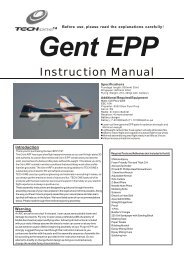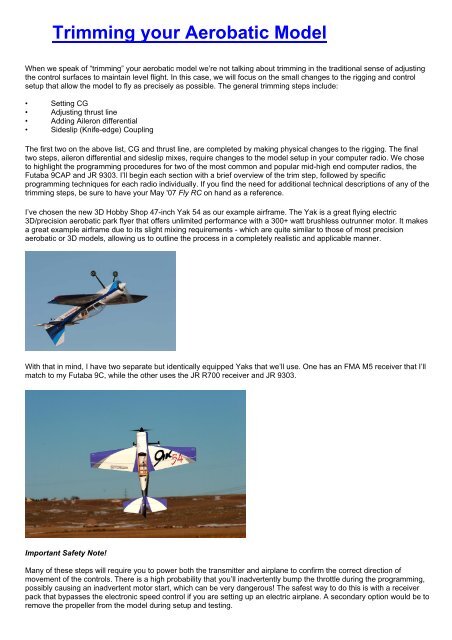
Trimming your Aerobatic Model - RC World
Trimming your Aerobatic Model - RC World
Trimming your Aerobatic Model - RC World
- No tags were found...

Create successful ePaper yourself
Turn your PDF publications into a flip-book with our unique Google optimized e-Paper software.
Aileron DifferentialIf you think back to the trimming process outlined in the companion print article, by the time you’ve reached the need foraileron differential you already set both the CG and the thrust line of <strong>your</strong> model. As a refresher on aileron differentialI’ve included an excerpt from the print article below:“With the CG and thrust lines set, the next step is to make <strong>your</strong> model roll axially as if on a string by adjusting ailerondifferential. Barring any manufacturer specific direction, I generally recommend symmetrical throws as a good startingpoint. Some models, however, just won’t roll axially with symmetrical throws, and aileron differential is a great solution.I find the best way to test for axial roll characteristics is on vertical down-lines. With the throttle closed, establish adown-line and begin a constant roll. Note any barreling of the roll. Perfectly trimmed, the model should maintain astraight vertical down-line while rolling axially as if on a taught string. To correct for a barreled roll, start by reducingthe throw of the down aileron for that roll direction incrementally. I find that small changes in differential - often just acouple of degrees, are enough. Don’t forget to also test the roll in the opposite rolling direction, as it isn’t uncommonfor the two rolling directions to be slightly different.Note, I recommend testing for axial rolls only on vertical downlines - not on level lines. The reason for this is that onvertical down lines there is no “up” or “down.” Any non-axial rolling tendencies noticed on the vertical line relate only tothe rolling characteristics of the model, not the effects of gravity. Also, unlike upright level flight where the wing is at aslightly positive or negative AOA, vertical lines are close to zero AOA. At zero AOA, we can truly assess whether themodel needs differential to roll axially.”So the burning question – how do we modify the aileron throws to allow differential? Different radio manufacturers giveyou different tools to accomplish this, so we’ll look at two of the more common techniques available.Before we do, however, I’d like to show you a really cool tool we’ll use to precisely measure control throw – the throwmeter.Several different versions are available, but the AeroWorks throw meter is one of my favorites. It uses a large clothespinas its attachment device which may be unacceptable for smaller models, but is ideal for the larger models I prefer.We’ll use the throw meter for measuring aileron differential, but it is also a great tool for setting dual rates and measuringcontrol throw in general.If an airplane displays the need for aileron differential, the most common corrective change is a reduction of the “down’aileron, i.e. reducing the throw of the throw on each aileron as it travels below the wing when viewed from above themodel. Once you establish the need for differential to make <strong>your</strong> model roll axially, you need to decide which of thefollowing two techniques will work with <strong>your</strong> transmitter setup – electronic differential or end point adjustment. The JR9303 allows differential while using dual aileron servos as flaperons, so that’s the first technique I’ll cover. The Futaba9CAP inhibits the differential function during flaperon use, so we’ll focus the end point technique for that radio.JR 9303 – Aileron Differential FunctionThe first step in setting up differential with the 9303 is to ensure that you are using the Flaperon mode to control the twoindividual aileron servos. Enter the system menu by holding the ENT button as you turn on the radio.
Select the Wing Type menu using the scroll wheel and ENT button.Scroll to the Wing: Icon and select Flaperon. With the radio now set toFlaperon mode, each aileron servo uses its individual slot in the receiverand the differential function is available to individually set the throw ofeach aileron.Exit the System menu by turning the radio off and back on again. Enter the Function menu by pushing the List button.Scroll to and select the Aileron Differential function.Notice the two separate “Position” settings – Pos 0 and Pos 1. These relate to the position of the dual rate switches, onesetting for each of the two dual rate positions. Initially the two settings will both indicate a linear mix, i.e. the same travelup and down. We need to change that to reduce the total travel of the aileron that moves below the wing. Selecting thefirst position (Pos 0) with the radio powered and the ailerons fully deflected, change the setting in either direction andnote which aileron moves and in which direction. If the up aileron moves, roll the setting the other direction until thedown aileron begins to reduce its throw towards neutral. I generally start with around 2-3% of differential and adjust asnecessary to fine tune the setting.In this instance after testing and resetting, I ended up with a differential of 7%, meaning that the aileron travels 7%further up than down. Also be sure to set both the Pos 0 and Pos 1 settings to the final mix. The photos below illustratethe magnitude of aileron throw reduction.
Neural aileron with the surface centered and the tail propped up to show zero degrees of throw on the throw meter30 degrees of throw up aileron.Approximately 28 degrees of down aileron throw.With this setting, the Yak rolls perfectly axially on both up and down lines.Futaba 9CAP – End Point Aileron DifferentialAs I mentioned earlier, the aileron differential function on the Futaba 9CAP is inhibited when using dual aileron servos inthe flaperon model, which is the mode I recommend for most aerobatic models. The aileron differential function on theFutaba 9CAP is designed to be used with multi servo sailplane wings. The solution is to set each aileron servos endpoint individually. The first step in that sequence is to ensure flaperons are selected. Enter the programming mode bypushing and holding the Mode/Page button. The screen will change to the Basic/Acro menu.
Pushing the Mode/Page button a second time puts the radio into the Advance/Acro function menu, which is where we’llactivate the flaperon function, allowing each aileron to be controlled independently.Highlight and select the Flaperon function.The flaperon is inhibited initially, so you’ll need to activate it along the top left side of that page. Next, ensure all aileronrates are set to 100% as shown in the picture above.With flaperons activated, each aileron servo can be controlled independently by adjusting the end point of eachindividual servo direction. Push the END button to return to the Advanced/Acro menu. Push the <strong>Model</strong>/Page button toreturn to the Basic/Acro menu. Highlight and select the End Point Function.Select the aileron channel. With the radio powered, input full aileron throw and reduce the end point watching whichaileron moves. If the up aileron moves, return its end point to the previous setting and attempt it in the opposite direction.You will want to reduce the down aileron throw by approximately 2-3% initially. This time I ended up with an 8%reduction.
Now for the confusing part – all you’ve adjusted to this point is the down aileron throw of one aileron. You need to repeatthis process for the other aileron. Using the Futaba 9CAP, I chose channel 5 for the second aileron servo, so I had testand set the end point for that servo as well. Note in the photo below that Channel 5 is selected, and although it showsthat channel as the Gear, it is the second aileron servo. Depending upon <strong>your</strong> particular setup, the second aileron servocould be assigned any of channels 5, 6 or 7.Sideslip (KE) CouplingMost models require some mixing for perfectly clean knife-edge flight and the modern computer radio makes this step aseasy as it can be. There are several different methods available to test for the need for sideslip (KE) coupling mixesincluding knife-edge flight and level flight rudder usage. If coupling is apparent in one, it is generally apparent in both.Again, let's look to the print article to more completely describe that process:“Sideslip coupling, more commonly known as knife-edge coupling, is the last trim adjustment I make. Some pilots startmaking this adjustment right away, but I find both CG and thrust line have an effect on sideslip coupling, so settingthose first, then coming back to sideslip mixing makes the most sense. Any adjustments to the sideslip coupling on<strong>your</strong> model are done through mixing functions on <strong>your</strong> transmitter. In reality, all we are doing is mixing in a certainamount of elevator or aileron with rudder deflection to compensate for sideslip coupling.Before we get too far into the discussion I think it’s important to clarify a misnomer – specifically that knife-edgecoupling only occurs during knife-edge flight. In reality, if a model displays knife-edge coupling, the same couplingexists anytime the model is flown in a sideslip condition. So what’s a sideslip condition? Uncoordinated flight would bethe technical answer to that question, but in layman’s terms, sideslip flight occurs virtually every time you deflect therudder in <strong>your</strong> model with the lone exception of coordinated turns. Next time you’re at the field, take a model withknown knife-edge coupling issues and aggressively deflect the rudder while in level flight. If <strong>your</strong> model pitches to thelanding gear and rolls with the rudder in knife-edge flight, it will also pitch to the gear and roll with the rudder from levelflight with rudder usage.The easiest test to determine the need for a sideslip mix is to simply apply rudder from level flight. If the model pitchesor rolls you’ll need to apply a mix with the rudder channel as the master, and the correction as the slave. Mostaerobatic models tend to pitch to the landing gear and roll one direction or the other. I generally start by mixing out thepitch coupling first, then focus on roll coupling. As a secondary test, fly knife-edge lines both directions and fine tune<strong>your</strong> previous adjustments. While I’ll discuss the technical aspects of setting sideslip mixes in a future article, itsimportant to note that you should never try to make any adjustments to <strong>your</strong> computer radio while flying – don’t ask, itsbeen attempted before with less than stellar results. I’ve found better luck drafting a flying buddy for scribe dutiesduring each flight to accurately record impressions, making adjustments after each flight. In most cases, I canaccurately tune sideslip mixes in less than 10 flights.One item to note, sideslip coupling is rarely identical from left to right. With one wing high in knife-edge flight, themodel may pitch to the landing gear slightly, and with the other wing high may pitch to the canopy. Simply adjust <strong>your</strong>mixes to match <strong>your</strong> particular model’s needs. Finally, I recommend you set up <strong>your</strong> sideslip mixes to be active during
all phases of flight. For precision aerobatics, there are very few instances in which the mix would hamper the precisionof <strong>your</strong> flight, as sideslip coupling applies any time the rudder is used.”So let’s apply that knowledge towards programming both the JR9303 and Futaba 9CAP. Both radios use programmablemixes that allow virtually any channel to be mixed with any other channel at either a specified linear ratio or along amulti-point curve (which allows adding an exponential component to the mix.) Applied to KE coupling, our goal is to mixsmall percentages of elevator and aileron with rudder to compensate for the coupling traits of each model. In the case ofthe 3D Hobby Shop Yak 54, in perfect knife-edge flight, the Yak pitches slightly to its belly and rolls slightly into therudder (left rudder gives left roll.) In a perfect world, we want the model to maintain a perfectly straight KE line with noadditional input from the pilot except rudder to maintain altitude. To achieve this with the Yak, we need to mix in upelevator to correct for a pitch to the landing gear, and aileron opposite the rudder direction (left rudder/right aileron, andso on.) Let’s start with the 9303.Rudder/Elevator Mixing – JR 9303The 9303 has a total of six programmable mixes in addition to several preset mixes. The first two programmable mixes,or P-mixes, allow you to adjust a variable rate mix over a total of seven programmable points, which is great because itallows a slightly non-linear mix if necessary. The remaining four P-mixes are all single ratio mixes that allow linearpercentage based mixing. I prefer to use the first two P-mixes for knife-edge coupling mixes as they allow me moreflexibility if a non-linear mix becomes necessary.Most computer radios mixing programs use a master/slave protocol, where you first set the “master” control, and thenadjust a percentage of “slave” control that will be mixed in with the master control. In our case, we want the master to bethe rudder, and we want to mix in a percentage of up elevator as the slave to overcome a slight pitch to the landing gearin knife-edge or sideslip flight. The first step is to enter the Function menu by pressing the LST button with thetransmitter turned on.Using the scroll wheel highlight and select Prog. Mix 1The mix will be inhibited initially, and you’ll need to activate it by placing the cursor over the INH icon and selecting it.With the mix active, the following screen allows you to make modifications to the mix, including master channel, slavechannel, and mixing percentages.
Note the master channel is the first channel listed, and the slave is the second channel listed – both are preset to throttleby the mixing logic. I recommend you start by setting the correct master and slave channels, which in our case themaster is the rudder, and the slave is the elevator. Then, zero out all of the mix ratios at each programmable point (i.e.Point- 0, Point- 1, and so on). When you’re done, the page should look like this.If you choose to switch <strong>your</strong> mixes on and off, now would be a good time to do so. There is a switch select icon on theleft side of the screen for this purpose. I, however, recommend leaving the mix on at all times. There are very fewinstances where this will present even the slightest problem, so the simplicity allowed by eliminating the need for anyadditional switching just makes sense.With the base mix menu set, it is time to adjust the values. In general, most small models require less than 10% mixingin either the pitch or roll sense. I would recommend starting with a small mix of 2-3%, followed by a test flight and furtheradjustments. The final numbers on the Yak were slightly higher than my initial estimate, so after test flying several times,I ended up with a rudder/elevator mix screen that looks like this.Looking at that screen, you’ll notice the two mixes aren’t exactly the same. One direction has slightly more mixpercentage than the other, and this is completely normal. It is rare that models need the same mix with rudder in bothdirections. Also note that the mix is basically linear, i.e. at full deflection, the mix point is 8, then at 2/3 deflection its 5,and at 1/3 deflection it is 3 – basically a straight line on the graph. The beauty of the 9303 is that it allows me to preciselyfine-tune the mix to match my airplane perfectly with its multi-point mix curve.Rudder/Aileron Mixing – JR 9303I generally use the second P-mix for rudder/aileron mixing and use the exact same technique for rudder/aileron mixingas I did for rudder/elevator. Start by activating the mix, setting the master and slave channels, and zeroing the mixvalues. Your screen should look like this.
On the Yak, I ended up with what I would describe as a 5% linear mix.Notice that the mix graph looks slightly different than the rudder/elevator graph. For the rudder/elevator mix, we wereusing up elevator for both directions of rudder deflections. With the rudder/aileron mix we use aileron opposite the rudderdirection, thus the graph of the rudder/aileron mix shows a line that extends above the baseline on the left, and belowthe baseline on the right. This indicates different directions of travel on each side of neutral rudder. Be sure when you’resetting the model up to check the actual direction of the mix by moving the flight controls and visually confirming the mixis moving the slave channel correctly.Rudder/Elevator Mixing - Futaba 9CAPThe Futaba 9CAP uses P-mixes that are similar to the 9303, with a total of seven Prog Mixes (P-mixes). The first fiveare a basic simple linear ratio mix, while mixes 6 and 7 each have a 5-point curve similar to the 9303. The procedure touse the multi-point mix is virtually identical to that used in the 9303 detailed above, so let’s take a look at applying one ofthe basic percentage mixes to compensate for coupling in the Yak.With the transmitter on, enter the Basic/Acro programming mode by holding the Mode/Page button.The Prog Mixes are located on the Advanced/Acro function page, which is reached by pressing the Mode/Page button asecond time.Remember, Prog Mixes 1-5 are a basic percentage mix and lack the ability to fine tune the mix through a multi-point mix.If you anticipate the need for the multi-point mix, I’d recommend using Prog Mixes 6 or 7. In my case, the Yak isperfectly happy with a basic linear mix, so I chose Prog Mix 1 for the rudder/elevator KE mix. Selecting P-mix 1 brings up
the following page.Notice that the Preset mix on Prog Mix 1 is inhibited and shows the incorrect master and slave. Both will need to beadjusted. Using the Select Cursor down button will move the cursor to the second page of Prog mix 1 until you come tothis screen.On this screen, you can activate the mix, change the master and slave channels, and add a switch selection to turn themix on or off if desired. Again, I leave all of my mixes on, so I simply set the switch position to null, which means itdisregards switch position and the mix is on constantly. Here is how the screen should look after setting the Rudder tothe master channel, the Elevator as the slave channel, and turning the mix on.With the second page of the mix complete, use the cursor button to return to page one of the Prog Mix 1 function to setthe precise values for the mix. In the case of the Yak, I settled on a 6% mix one direction and an 8% mix in the other.Like before, you’ll want the airplane powered and close-by to confirm that the mix is working correctly. In our case, wewant up elevator mixed with rudder movement in both directions.Rudder/Aileron Mixing – Futaba 9CAPThe procedure for mixing rudder/aileron with the Futaba 9CAP is nearly identical to mixing rudder/elevator describedabove. Knowing that my KE coupling needs are very linear, I again chose to use a simple percentage Prog Mix. I choseProg Mix 2. Start by opening up <strong>your</strong> preferred Prog Mix, setting the master and slave channels, and activating the mix.One additional step is necessary to ensure both ailerons respond to the mix, and that is to turn the “Link” on. The linkfunction is used to link both aileron servos to the mix. With the link off, the radio will only mix the primary servo plugged
into the aileron channel (channel 1). With the link activated, both aileron servos will be used when mixing aileron as aslave. With that complete, <strong>your</strong> screen should look like this.Returning to page 1 of Prog Mix 2, set the desired values. Again, with the model powered and close-by, confirm thecorrect direction of control movement. In our case, we want aileron deflection opposite the rudder deflection.ConclusionFrom my May 2007 Fly <strong>RC</strong> article, “I’ve heard many competition pilots describe the trimming process as a never-endingcircle. Each additional change you make can force modifications to previous changes. I find, however, that most sportaerobatic pilots require only one trip through the steps outlined above to dramatically improve their models precisionaerobatic flying traits. By following the basic order of adjustments outlined above, you will be making the model fly moreprecisely on its own.This means less to think about, allowing you to focus on flying each figure as precisely as possible. Some look down onelectronic mixing. Many others widely accept mixing as reasonable and necessary to achieve the best possible flyingmodel. I find it to be very helpful and from my perspective, any adjustments you can make to help <strong>your</strong> model fly preciselines, roll axially, and maintain clean knife-edge passes is time well spent.”Setting up <strong>your</strong> model for precision aerobatics is time well spent. We hope that by combining the information found inthis article with the May 2007 print article you’ll soon be flying more precisely than ever. Till next time, remember,aerobatics make the world go ‘round.