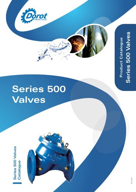
Series 500 Catalogue - Dorot Control Valves
Series 500 Catalogue - Dorot Control Valves
Series 500 Catalogue - Dorot Control Valves

Create successful ePaper yourself
Turn your PDF publications into a flip-book with our unique Google optimized e-Paper software.
<strong>Series</strong> <strong>500</strong> <strong>Valves</strong>Areas Of ActivityWaterworks<strong>Dorot</strong>’s valves are especially designed to comply with all the demands of Waterworks systems suchas Pressure Management, Low Flow Regulation, Leakage Prevention, Pump <strong>Control</strong>, Level <strong>Control</strong>,Surge Prevention, Wastewater and Water Treatment.Irrigation<strong>Dorot</strong> is a leader in Automatic <strong>Control</strong> valves for irrigation applications: Drip Irrigation, Greenhouses,Turf and Landscaping. The innovative state of the art products are made of a variety of materials suchas Cast Iron, Ductile Iron, Steel, Stainless Steel, Bronze, Polyamide and uPVC.Construction And Industry<strong>Dorot</strong> offers control applications for high rise buildings such as Flow and Pressure Regulation, WaterHammer Prevention and Reservoir Level <strong>Control</strong>.Fire Protection<strong>Dorot</strong> offers a variety of valves for Fire Protection applications with UL Approvals.Filtration And Water Treatment<strong>Dorot</strong> offers a variety of Back Flushing valves for Filtration Systems. These valves are made of highdurability materials for water treatment of aggressive media.2Edition 10/2012
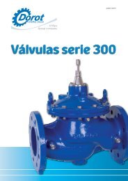
General Information<strong>Series</strong> <strong>500</strong> <strong>Valves</strong>OverviewThe <strong>Dorot</strong> <strong>Series</strong> <strong>500</strong> is a unique, cost effective control valve for water-works and irrigation systems. It is designed forsuperb regulation capabilities, combined with low pressure loss in the fully open position.The experts at <strong>Dorot</strong> developed this technically-advanced product line with capabilities far beyond most other valves.This guide will asist you in the selection of the optimal DOROT <strong>Series</strong> <strong>500</strong> valve.FeaturesOption for SST indicator rodWide body shape prevents cavitationdamage, and ensures very low noiseduring operation.Coating:UV resistant and certifiedfor use in potable waterapplicationsWear & corrosion resistantSST seatInnovative diaphragm-trimassembly guided by lowfrictiontop & bottom guidesLTP® (Linear ThrottlingPlug) for superior low flowregulationSpecial valve design:reduction in head-lossesFeatures of the <strong>500</strong> <strong>Series</strong>• The capability to regulate at “near zero” flow, as astandard feature on all sizes, achieved by the LTP ®(“Linear Throttling Plug”) device, completely eliminatesthe need for a low flow bypass valve, or internalthroteling device such as U-port or V-port.• The unique bottom guide together with thehydrodynamically designed structure enable very lowhead loss in the ”fully-open” position.• A standard valve model fits a wide variety of controlapplications using <strong>Dorot</strong> pilot valves.• An especially short face-to-face dimension, ensuresmaximal saving in installation space.• An innovative internal trim ensures frictionlessoperation, easy maintenance and high reliability.• During closure, the pace slows down to preventslamming or water hammer / surges.• The series includes a position indication rod, as anoptional feature, attached by a floating connection,enabling smooth movement of the indicator.• Very quiet and stable operation makes the valvesespecially suitable for housing and residentialapplications.• All materials are WRAS & NSF approved for potablewater.3Edition 10/2012
<strong>Series</strong> <strong>500</strong> <strong>Valves</strong>Engineering DataTechnical DataDiameter 40mm (1 1 / 2”) 50mm (2”) 65mm (2 1 / 2”) 80mm (3”) 100mm (4”) 150mm (6”) 200mm (8”)m 3 /h GPM m 3 /h GPM m 3 /h GPM m 3 /h GPM m 3 /h GPM m 3 /h GPM m 3 /h GPMNominal flow 11 50 20 80 20 80 40 180 75 325 160 705 280 1240Max. continuouce flow 25 110 40 175 40 175 100 440 160 705 350 1540 620 2730Max. intermittent flow 35 160 55 250 55 250 145 640 225 995 510 2240 900 4000Minimal flow< 1 m 3 /h / GPMKv [m 3 /h@1bar] 45 45 45 110 175 400 620Cv [gpm@1psi] 53 53 53 128 204 467 724K [dimensionless] 2 4.9 14.1 5.4 5.2 5 6.5Dimensions and WeightsValve Size 40 Th (1 1 / 2”)50 Th(2”)50A Th (2”)50A F(2”)50 F(2”)mm inch mm inch mm inch mm inch mm inchL 202 7 15 / 16 202 7 15 / 16 156 6 1 / 8 193.5 7 5 / 8 200 7 7 / 8HH 169 6 5 / 8 169 6 5 / 8 185 7 1 / 4 211 8 5 / 16 214 8 7 / 16W 116 4 9 / 16 116 4 9 / 16 115 4 1 / 2 165 6 1 / 2 165 6 1 / 8R 38 1 1 / 2 38 1 1 / 2 117 4 5 / 8 111 4 3 / 8 82.5 3 1 / 4Weight *Kg Ibs Kg Ibs Kg Ibs Kg Ibs Kg Ibs4.8 10.7 4.6 10.2 5.2 11.5 9.8 21.8 9.5 21.1RWLValve Size65 F(2 1 / 2”)80 F(3”)100 F(4”)150 F(6”)200 F(8”)mm inch mm inch mm inch mm inch mm inchL 210 8 1 / 4 285 11 1 / 4 305 12 390 15 3 / 8 495 19 1 / 2H 224 8 13 / 16 293 11 9 / 16 330 13 450 17 3 / 4 557 21 15 / 16W 185 7 1 / 4 200 7 7 / 8 220 8 11 / 16 285 11 1 / 4 386 15 3 / 16R 92.5 3 5 / 8 100 3 15 / 16 110 4 5 / 16 142.5 5 5 / 8 170 6 11 / 16Kg Ibs Kg Ibs Kg Ibs Kg Ibs Kg IbsWeight *12 26.6 21 46.6 26 57.7 60 133.2 118 262H* Approximate Shipping WeightF - Flanged Th - Threaded A - AngleRL4Edition 10/2012
Engineering Data<strong>Series</strong> <strong>500</strong> <strong>Valves</strong>Flow chart1 /2 ”1 1 / 2 ” - 2” - 2 3” 4” 6”8”2 way control system3 way control systemm 3 / hFlowGPMTechnical specificationsAvailable sizes 40 to 200 mm (1 1 / 2” to 8”)Operating pressureTemperature rangeEnd connectionsCoating0.5 to 16 bar (7 to 250 psi)60°C (140°F)<strong>Valves</strong> diameters 50-200 mm (2” - 8”) supplied in the following international flange standards:ISO 7005; ANSI B16; AS10; JIS B22. Other standards are available upon request.<strong>Valves</strong> diameters 40-50 mm (1 1 / 2” - 2”) supplied also in the following threadstandards: F-BSP; F-NPTElectrostatically applied, oven baked Polyester. Epoxy on request.MaterialsComponentsComponent No. Description Materials1 Body Ductile Iron2Trim: LTP, Guides and topdiaphragm retainerComposite Materials(WRAS & NSF approved GRP)3 Trim bolts SST4 Trim cylinder40-65mm/1 1 / 2 ”-2 1 / 2 ” - SST80-200mm/3”-8” - Ductile Iron5 Cover Ductile Iron6 Spring SST7 Cover bolts SST8 Washer SST9 Diaphragm Reinforced EPDM Rubber10 Plug seal NBR Rubber11 Seat SSTGRP: Glass Reinforced polyamideSST: Stainless Steel87910111 2 3 4655Edition 10/2012
<strong>Series</strong> <strong>500</strong> <strong>Valves</strong><strong>Control</strong> ApplicationsRemote <strong>Control</strong> & Check <strong>Valves</strong>EL - Solenoid <strong>Control</strong>led ValveA 3-way solenoid valve, activated by an electric current or an electric pulse,opens or closes the main valve. The standard valve is “normally close”. The“normally open” is optional.Electric activation can be added to other control applications on request.ELCV - Hydraulic Check ValveThe valve is in the “open” position when the upstream pressure is higher thanthe downstream pressure.Should the upstream pressure drop below the downstream pressure, thevalve will instantly close, preventing return flow.Opening and closing speeds are adjustable.CVRC - Hydraulic Remote <strong>Control</strong> ValveA hydraulic relay opens or closes the valve, in response to a pressurecommand, carried by a control tube from a remote control center.Pressure Reducing <strong>Valves</strong>PR - Pressure Reducing ValveThe valve maintains a preset downstream pressure, regardless of upstreampressure or flow rate fluctuation.The main valve is controlled by either a 3-way pilot valve (allowing full openingwhen downstream pressure drops below the set-point), or by a 2-way pilotvalve (creating minimal pressure differential in open position).PRPR/EL - Electrically Operated Pressure ReducingValveThe valve is a Pressure Reducing Valve which maintains a preset downstreampressure, regardless of upstream pressure or flow rate fluctuation.The valve’s opening is controlled by an electric solenoid valve. This eithercauses the valve to open (and regulate) or to close.PR/EL6Edition 10/2012
<strong>Control</strong> Applications<strong>Series</strong> <strong>500</strong> <strong>Valves</strong>Pressure Sustaining & Relief <strong>Valves</strong>PS - Pressure Sustaining ValvePS(R) - Pressure Relief ValveThe valve maintains upstream pressure, regardless of flow rate variations.The valve will be in the “closed” position if the upstream pressure dropsbelow the set-point and will be “fully-opened” when the upstream pressureexceeds the set-point.PS PS(R)DI - Pressure Differential Sustaining ValveThe valve maintains a preset pressure differential between the upstreamand downstream pressures. The valve controls booster pumps discharge,heating and cooling systems, bypass configurations and more.QR - Quick-Relief Safety ValveThe valve opens instantly when the pressure in the pipeline exceeds the safelevel, thus relieving excessive pressure from the network. When the pressurereturns to normal, the valve closes slowly, at an adjustable pace.QRFlow Rate <strong>Control</strong> <strong>Valves</strong>FR - Flow Rate <strong>Control</strong> ValveThe valve limits the flow rate in the network to a preset value, regardless ofpressure variations.The valve opens fully when the flow rate drops below the set-point.FE - Excessive Flow Shut-Off ValveThe valve closes when the flow rate exceeds the normal value (dueto pipeline rupture for example). Reopening is by manual reset only.FE FR7Edition 10/2012
<strong>Series</strong> <strong>500</strong> <strong>Valves</strong><strong>Control</strong> ApplicationsLevel <strong>Control</strong> <strong>Valves</strong>FL - Modulating Float <strong>Control</strong>led ValveThe main valve is controlled by a float valve, located in the tank or reservoirand set at the required maximum water level. The valve maintains themaximum level continuously.Optional Addition: Surge-Preventing Closure (SA).FLFLDI - Differential Float <strong>Control</strong>led ValveA Float valve (model 70-550) controls the main valve, closing it whenthe water reaches maximum level, and opening it when the waterdrops to its preset minimum level. The differential between themaximum and the minimum levels is adjustable, at a wide range.Optional Addition: Surge-Preventing Closure (SP).FLDIFLEL - Electric Float-<strong>Control</strong>led ValveAn automatic, level control valve, activated by an electric float that operatesthe main valve by a solenoid.Enabling adjustable differential of the max / min levels.Optional addition: surge-preventing closure (SP)FLELAL - Altitude <strong>Control</strong> ValveThe main valve is controlled by a highly sensitive pilot, located outside thetank. The pilot opens or closes the valve in response to the static pressure ofthe water. The pilot allows for differential adjustments between the maximumand minimum level.Optional Addition: Surge-Preventing Closure (SP).ALSpecial <strong>Control</strong> ApplicationsSP - Surge-Preventing ClosureThe device automatically adjusts the closing speed of a valve that is locatedat the end of a long pipeline, preventing pressure surges.Please consult DOROT, or your local distributor for details.8Edition 10/2012
Ordering Guide<strong>Series</strong> <strong>500</strong> <strong>Valves</strong>Ordering guideTypeOrdering data Ordering code Ordering datam □ □ □□ □□ □□Straight flow → -Angle → A <strong>Control</strong> FunctionsIndicator Rod 00 None (basic valve only)No → - M Manual controlYes → I EL Electric solenoid control *Diameter RC Hydraulic Relay control *1 1 / 2 " / 40mm → 15 PR Pressure Reducing2" / 50mm → 02 PS Pressure Sustaining / Relief2 1 / 2 " / 65mm → 25 QR Quick Pressure Relief3" / 80mm → 03 DI Differential P. Sustaining4" / 100mm → 04 FR Flow Limiting6" / 150mm → 06 FE Excessive Flow Shutoff8" / 200mm → 08 FL Level-Float pilot controlledEnd Connections AL Level-Hydrostatic pilot controlledISO16 → I1 TO Two stage openingANSI 125 / 150 → A1 SP Surge preventing closure (upstream)FlangeBS TD / AS TD → BD CV Hydraulic Non ReturnJIS-10 → J1 EC PLC controlledUn-drilled → UN XX Other (specify)ThreadBSP → BS * Please specify N.O or N.CNPT → NPOther (specify) → XXOrdering example:50 A I 02 A1 PR / PS / EL (N.C)An Angle-pattern, with an indication rod, 50mm / 2” size, flanged to ANSI 150, pressure reducing and sustaining,opened by an electric command9Edition 10/2012
Pressure rating: 10 bar / 145 psi‘Galit’ 25-300 3-way / 2 positions NC NO or w. NO, 3/8" small ports hydraulic hydraulic relay relay‘GALIT’ 25-300‘Galit’ 3-way / 2 positions NC or NO, small hydraulic relay‘GALIT’ 25-300Plastic RelaysFor valve sizes 20mm to 150mm - 3 /4" Pilots to 6" and Accessories <strong>Series</strong> <strong>500</strong> <strong>Valves</strong>Pressure Metal Relays rating: 10 bar / 145 psi25-300 For 3-way / 2 positions NO w. 3/8" ports hydraulic relayMetal valve Relays sizes 40mm to 600mm - 1 1 /2" to 24"Pressure ‘Galit’ 3-way / 2 positions NC or NO, small hydraulic relay‘GALIT’ 25-300For valve rating: sizes 40mm 25 bar to / 360 600mm psi - 1 1 /2" to 24"66-210 Pressure rating: 3-way 25 / 2 bar positions / 360 psi NO (66-213: NC) hydraulic relay66-300 66-210 3-way adjustable / 2 positions hydraulic NO (66-213: relay NC) hydraulic relayRelay-<strong>Valves</strong>28-200 66-300 3-way 2-way adjustable / 2 positions hydraulic hydraulic relay relay66-210 66-310 28-200For valve sizes28-200 Metal40mmRelays 2-wayto/ 2600mmpositions hydraulic- 1 1 / 2” torelay66-210 66-310 28-20024”Pressure rating:For valve25sizesbar40mm/ 360to 600mmpsi- 1 1 /2" to 24"Mini Solenoids66-210 3-wayPressure/ 2 positionsrating: 25 barNO/ 360(66-213:psiFor NC) hydraulic relay66-310 3-way 66-210 Mini irrigation Solenoids valve sizes 20mm to 150mm -adjustable 3-way / 2 hydraulic positions NO relay (66-213: NC) 3 /4" to 6"hydraulic relay28-200 2-way 66-300 For Pressure irrigation rating:/ 2 positions 3-way valve 10 baradjustable sizes / 145 20mm psihydraulic hydraulic to 150mm relay- 3 /4" to 6"Operating28-200 Pressure rating: Voltage:2-way 10 / bar 2 positions / 145 psi hydraulic relay28-310 66-210 66-310 28-20028-310 3-way AC: Operating 24V / 2 positionsVoltage:NO/NC hydraulic relayDC: AC: 24V 12V or 24VMini Latch DC: 12V Solenoids6-40V or 24VFor D2 Latch irrigation 6-40V 2-way valve NC sizes solenoid 20mm valve to 150mm -Heavy-duty Solenoid <strong>Valves</strong>3 /4" to 6"D2D3Pressure D3 D2 rating: 3-way 2-way 10 NC bar solenoid or / NO 145 solenoid psi valve valveD2D3Operating D3 3-way Voltage: NC or NO solenoid valveFor valve sizes AC: 24V 20mm to 600mm - 3 / 4” to 24”Pressure rating: Heavy-dutyDC: 12V According Solenoidsor 24V to the selected orifice andsolenoid type ForLatch Heavy-duty valve sizes6-40V Solenoids 20mm to 600mm - 3 /4" to 24"Operating VoltageD2 For Pressure valve rating: sizes 2-way(others 20mm AccordingNC solenoidavailable to 600mm to the selectedvalve - upon 3 /4" to 24" orifice request): and solenoid typeAC: 24V, 110V OperatingD3 Pressure or rating: 220V Voltage D2D33-way According (othersNC NO to availablesolenoid the selected uponvalveorifice request): and solenoid typeDC: 12V or AC: Operating 24V 24V, 110V Voltage or 220V (others available upon request):Latch 9V, 12V, DC: AC: 24V, 12V 24V or 110V 24Vor 220VB2 2-way NC Heavy-duty Latch DC: 12V or 9V, NO or 12V, 24V Solenoids solenoid 24V valveB3 3-way NC For B2 Latch valve or 9V, NO sizes 12V, 2-way solenoid 24V 20mm NC or to NO 600mm valve solenoid - 3 /4" valve to 24"s80 3-way Pressure B3 NC or rating: NO 3-way solenoid According to valvethe selected s80B2B3B2 2-way NC NO solenoid valveorifice and solenoid typeOperating B3 3-way Voltage NC (others or NO available solenoid upon valverequest):B2B3AC: 24V, 110V or 220VDC:<strong>Control</strong>12V orFilters24VLatch 9V, 12V, 24V<strong>Control</strong> Self-Flushing, Inline Stainless steel screen filter, located within theB2<strong>Control</strong> Filtersmain valve,2-wayand rinsedNC orcontinuouslyNO solenoidbyvalvethe streamSelf-Flushing, B3Self-Flushing,Inline 3-way Stainless NC or NO solenoid valve screen filter, locatedB2B3Sizes: 1 /4", 1 Inline Stainless steel screen filter, located within the/2"within the main valve,External,valve, and"Y" typeand rinsed- Stainlessrinsed continuouslysteelcontinuously by the streamscreen installedbyin athe"Y"streamSizes: 1 / 4”, 1 Sizes:shaped/ 2”, 1 /4", 1 /2"body on the pressure source.External, “Y” External, type - Stainless installed in a “Y”Sizes:shaped body <strong>Control</strong> 3 "Y"/8",the Filters1 type - Stainless steel screen installed a "Y"shaped body /2"pressure on the pressure source.External,Sizes: 3 / 8”, 1 Self-Flushing, large/ 2”Inline - A large Stainless volume steel external screen filter“Y Filter” Self Flushing FilterSizes: 3 /8", 1 /2"filter, located within theExternal, large External, main valve, - A large large and - rinsed A large volume continuously volume external by the filter filter streamLarge Filter“Y Filter” Self Flushing FilterSizes: 1 /4", 1 /2"External, "Y" type - Stainless steel screen installed in a "Y"shaped body on the pressure source.Sizes: 3 /8", 1 /2"External, large - A large volume external filter“Y Filter” Self Flushing Filter<strong>Dorot</strong>CONTROL VALVES E V E R Y T H I N G I S U N D E R C O N T R O L<strong>Dorot</strong>CONTROL VALVES E V E R Y T H I N G I S U N D E R C O N T R O L<strong>Dorot</strong>CONTROL VALVES E V E R Y T H I N G I S U N D E R C O N T R O L11Edition 10/2012
InnovationInnovationExpertiseExpertiseReliabilityReliabilityHundreds of companies in the industrial,civil engineering, municipal and agriculturalsectors around the world have chosenDOROT’s innovative and field-proventechnologies. Since its establishment in 1946,DOROT leads the hydraulic valves marketwith continued innovation, uncompromisingexcellence and firm commitment to itscustomers, consulting and supportingthem through all stages of a project andovercoming challenges in R&D, design,implementation, and maintenance.www.dorot.com