

DGLR-MTR-2000.PDF
DGLR-MTR-2000.PDF
DGLR-MTR-2000.PDF

Create successful ePaper yourself
Turn your PDF publications into a flip-book with our unique Google optimized e-Paper software.
THE SUCCESSFUL DEVELOPMENT HISTORY OF THE <strong>MTR</strong>390 TURBOSHAFT<br />
ENGINE FROM THE DEFINITION OF THE DESIGN TO THE SERIES PRODUCTION<br />
P. Schinzl 1) , F. Malzacher 1) , P. Moncoutie 2) , B. Brereton 3) ,<br />
G. Schuberth 4) , M. Lauvaux 4)<br />
1) DaimlerChrysler Aerospace, MTU München<br />
2) Turbomeca<br />
3) Rolls Royce<br />
4) <strong>MTR</strong> GmbH<br />
1. ABSTRACT<br />
This paper presents the <strong>MTR</strong>390 turboshaft engine<br />
used to power the Tiger attack helicopter by an emphasis<br />
of the development history. The <strong>MTR</strong> organisation<br />
who produce the engine, and the workshare of the<br />
three partner companies, MTU, TM and RR is described.<br />
Modularity, maintenance and the growth<br />
potential of the engine are covered, as well as engine<br />
design and test experience. A summary of the programme<br />
status is presented with an overview of other<br />
potential applications for the engine.<br />
2. INTRODUCTION<br />
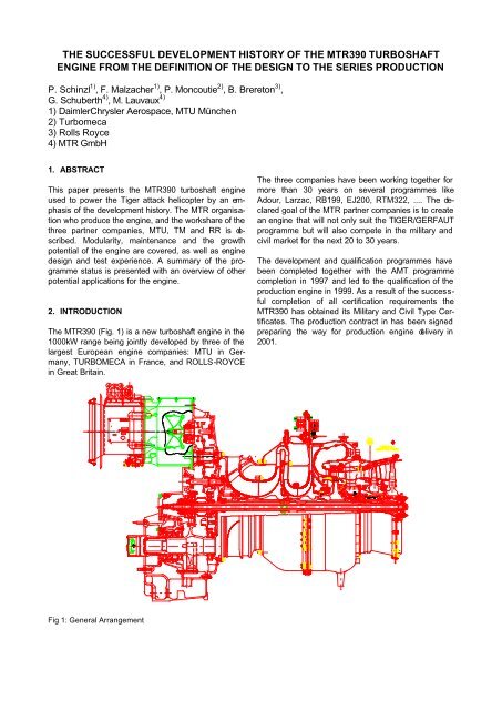
The <strong>MTR</strong>390 (Fig. 1) is a new turboshaft engine in the<br />
1000kW range being jointly developed by three of the<br />
largest European engine companies: MTU in Germany,<br />
TURBOMECA in France, and ROLLS-ROYCE<br />
in Great Britain.<br />
Fig 1: General Arrangement<br />
The three companies have been working together for<br />
more than 30 years on several programmes like<br />
Adour, Larzac, RB199, EJ200, RTM322, .... The declared<br />
goal of the <strong>MTR</strong> partner companies is to create<br />
an engine that will not only suit the TIGER/GERFAUT<br />
programme but will also compete in the military and<br />
civil market for the next 20 to 30 years.<br />
The development and qualification programmes have<br />
been completed together with the AMT programme<br />
completion in 1997 and led to the qualification of the<br />
production engine in 1999. As a result of the successful<br />
completion of all certification requirements the<br />
<strong>MTR</strong>390 has obtained its Military and Civil Type Certificates.<br />
The production contract in has been signed<br />
preparing the way for production engine delivery in<br />
2001.
3. ENGINE PARTNERSHIP<br />
MTU TURBOMECA ROLLS-ROYCE GMBH (<strong>MTR</strong>)<br />
GmbH is a joint company established under German<br />
law in Munich in 1989 by MTU Motoren- und Turbinen-<br />
Union München GmbH, Turbomeca S.A. and Rolls-<br />
Royce plc.<br />
The purpose of the company is<br />
• to act as contractual party vis-à-vis the authorised<br />
governmental authorities and other potential customers<br />
for the <strong>MTR</strong>390 engine<br />
• to responsibly manage and coordinate among the<br />
partner companies the development, airworthiness,<br />
production preparation, production, marketing,<br />
sales, licensing and support of the <strong>MTR</strong>390<br />
engine.<br />
MTU:<br />
MTU Munich is part of DaimlerChrysler AG and responsible<br />
for all aero engine business as the leading<br />
German engine company.<br />
MTU is in charge of the design and manufacture of the<br />
Combustion Chamber, the High Pressure Turbine, the<br />
interduct and rear bearing chamber and the oil cooler<br />
Turbomeca (TM):<br />
Turbomeca, as part of the French SNECMA Aero<br />
Engines Group, is the world leader in turboshaft engines<br />
for helicopters. Its engines cover the largest<br />
power range from 450 to 3.000 shp and equip helicopters<br />
made by the world’s leading manufacturers.<br />
TM is in charge of the design and manufacture of the<br />
compressor (LP - HP), the gearbox (reduction and<br />
accessory drive), most of the accessories and the<br />
FADEC<br />
Rolls-Royce (RR):<br />
Rolls-Royce is a world-leading power systems business<br />
meeting the needs of customers in propulsion,<br />
electrical power and materials handling around the<br />
world.<br />
RR is in charge of the design and manufacture of the<br />
power turbine, the stub shaft and the power turbine<br />
shaft<br />
4. MAIN ENGINE FEATURES<br />
The <strong>MTR</strong> architecture is the result of an optimisation<br />
study, commonly carried out by the three partner<br />
companies.<br />
High efficiency<br />
centrifugal compressor High efficiency<br />
power turbine<br />
Main reduction and<br />
accessory<br />
gearbox<br />
Integral oil system<br />
Fig. 2: Engine architecture<br />
Annular reverse-flow<br />
machined ring combustor<br />
for increased durability<br />
5. DEVELOPMENT HISTORY<br />
Advanced air-cooled<br />
gas generator turbine<br />
for lower cost and<br />
increased reliability<br />
The development of the <strong>MTR</strong>390 engine started officially<br />
on 1 st January 1988. Within two years, the<br />
technical requirements were specified and the main<br />
development contract was approved by the end 1989<br />
followed by the first engine run in December 1989.<br />
The engine development phase was divided into three<br />
major steps:<br />
- Qualification A: Preliminary flight release<br />
- Qualification B: Military Type Certificate (Musterzulassung)<br />
- Qualification C: Release of the production standard<br />
The first development phase – Qualification A – was<br />
required for the clearance of the <strong>MTR</strong>390 engine for<br />
the FTB (flying test bed) and prototype testing. In<br />
accordance with an agreed qualification procedure,<br />
engine and accessories tests i.e. 60 hrs endurance<br />
run, vibration investigation, engine overspeed tests,<br />
software integration, power turbine overspeed test (cut<br />
shaft), oil and fuel system performance tests, oil flow<br />
interruption test in order to clear negative g flights,<br />
equipment vibration and fire tests etc., were successfully<br />
performed. The completion of these tests with the<br />
so-called engine standard 1A ended in the clearance<br />
for FTB tests in the ‘Panther’ helicopter and flight<br />
tests in the ‘Tiger’ prototype helicopter.<br />
The first FTB flight was successfully performed with<br />
two <strong>MTR</strong>390 engines on 14 th February 1991 while the<br />
first flight on the ‘Tiger’ prototype helicopter PT1 took<br />
place with prototype engines on the 25th April 1991.<br />
The main subject of Qualification B (Military Type<br />
Certificate) and C was to satisfy the Airworthiness
equirements and to release the production engine<br />
standard.<br />
With a ‘new’ defined engine standard 2A, additional<br />
engine and rig qualification tests were carried out and<br />
successfully completed, i.e.<br />
• rain ingestion test<br />
• snow ingestion test (simulated with crushed ice)<br />
• 150 hrs type endurance run<br />
• overspeed tests<br />
• vibration surveys<br />
• oil/fuel clearance runs within several 150 hrs endurance<br />
tests<br />
• 30 seconds OEI demonstration (8 shots of 30’’<br />
each)<br />
• inclination tests<br />
• accelerated mission testing (2 engines, each<br />
1.200 hours running) representing an ageing<br />
equivalent to 4.300 Tiger mission hours;<br />
• sand ingestion tests (with and without sand filter)<br />
• corrosion test<br />
• exhaustive aircraft - engine interface qualification<br />
(control system, …)<br />
One important step in achieving this qualification<br />
milestone was the test campaign performed on the<br />
altitude test facility (ATF) at Centre d’Essais des<br />
Propulseurs (CEPr) in France. Within several test<br />
phases the following major qualification justification<br />
were performed:<br />
• Demonstration of the starting and restarting envelope<br />
• Demonstration of the auto-relight function within<br />
the operating envelope<br />
• Demonstration of the specified engine performance<br />
within the operating envelope<br />
• Clearance of engine fuels and oil brands for operation<br />
within the specified envelope<br />
• Icing test with a representative helicopter air intake.<br />
Based on the engine qualification evidence (engine<br />
tests, analyses, FMECAs, etc.) the engine standard<br />
2A was granted the military Type Certificate by the<br />
German Airworthiness Authorities on the 09.05.1996.<br />
Subsequent to the issue of the Type Certificate, the<br />
development of the engine and software concentrated<br />
on performance improvement, optimisation of acceleration<br />
and deceleration software laws and consideration<br />
of maintenance aspects. In order to separate the<br />
Qualification B and C standards, an interim standard<br />
(2B) was introduced with improved performance features<br />
and improved ease of maintenance. This led to<br />
the introduction of some modifications. Although most<br />
of the qualification tests were performed with the engine<br />
standard 2A, all results achieved were transferred<br />
to the final qualification standard which will be declared<br />
as engine build standard 2C at the end of the<br />
engine development phase. The successful comple-<br />
tion of qualification of the <strong>MTR</strong>390 engine closed with<br />
the handing over of the Qualification C Certificate by<br />
the military customer.<br />
In parallel to the military certification activities, <strong>MTR</strong><br />
started to gain the civil type certificate. From the very<br />
beginning of the development programme, a civil application<br />
of the <strong>MTR</strong>390 was intended and therefore<br />
the <strong>MTR</strong>390 engine specification is based on two<br />
main airworthiness regulations, the British Civil Airworthiness<br />
Requirements (BCAR) Section C, issue<br />
13, which is equivalent to JAR-E change 6 and the<br />
Military Specification MIL-E-8593A.<br />
In November 1992, <strong>MTR</strong> contacted the LBA in order to<br />
discuss possible ways of obtaining the Civil Type<br />
Certificate for the <strong>MTR</strong>390 turboshaft engine. As result<br />
of these discussions <strong>MTR</strong> decided in November<br />
1994 to apply for a German Type Certification in the<br />
frame of a Simplified Type Investigation according to<br />
§4 LuftGerPO.<br />
The reason for selecting this way was that the company<br />
preferred to use the advantage of the German<br />
Procedures to avoid additional costs potentially resulting<br />
in a repetition of the majority of certification activities<br />
which would have resulted when using the Joint<br />
European Procedures.<br />
This route was possible because the Military Certification<br />
Basis was JAR-E, change 6. Therefore <strong>MTR</strong><br />
complies with the German regulations that require the<br />
same level of safety in the case that the LBA validates<br />
a German Military Type Certificate.<br />
At the beginning of June 1997 the final civil documentation<br />
was submitted and accepted by the German<br />
Civil Airworthiness Authorities supported by the German<br />
Military Authorities. Based on the evidence given<br />
to both Airworthiness Authorities, the Civil Type Certificate<br />
was granted by LBA on 19 June 1997.<br />
6. ENGINE DETAILS<br />
6.1 Compressor<br />
The compressor is a two stage centrifugal system<br />
providing a pressure ratio of 14 with high efficiency.<br />
The important surge margin enabled to delete the<br />
bleed valve after extensive rig and engine testing.<br />
The centrifugal compressor is particularly well<br />
adapted for small turbo-shaft engines because it reduces<br />
the engine compartment length for installation<br />
into the aircraft and also vulnerability to battle damage<br />
for military applications.<br />
Its simple design with a minimum of parts (2 stages,<br />
no bleed valve, no IGVs ) is an advantage for a good<br />
reliability.
It demonstrated particularly good tolerance to FOD<br />
during the development and qualification tests (sand,<br />
ice, water, …).<br />
Both stages can be easily inspected with boroscopes<br />
in order to monitor the mechanical<br />
condition.<br />
6.2 Combustor<br />
A reverse-flow annular combustor was chosen for its<br />
advantages regarding the whole engine architecture.<br />
Best adapted to the centrifugal compressor design, it<br />
minimises engine length, provides good accessibility<br />
to fuel nozzles and allows a short and rigid generator<br />
rotor.<br />
The combustor [1] can be shortened only provided<br />
rapid fuel conversion is achieved in its primary combustion<br />
zone. Primary zone conversion is controlled<br />
by the fuel mixing and vaporisation subprocesses.<br />
These processes can be precipitated by achieving a<br />
preferably small size of fuel droplet, a high relative<br />
velocity between the drops and the gas, a preferably<br />
homogeneous fuel distribution in the primary zone,<br />
and a high turbulence level conducive to efficient mixing.<br />
Therefore, the fuel conditioning system proved to<br />
be a key criterion.<br />
In order to improve the fuel conditioning system MTU<br />
developed a new type air blast atomiser which is illustrated<br />
in Fig. 3.<br />
Fig. 3 Air blast atomiser<br />
According to this design the fuel is sprayed onto a<br />
venturi insert by means of a pressure atomiser. The<br />
two counter-rotating primary zone vortices concentrates<br />
the burning process in the centre of the primary<br />
zone. The secondary airstream forms a layer on the<br />
flame tube wall. This system prevents contact of the<br />
burning gases with the flame tube walls. Fig. 4 shows<br />
the flame generated by this type of atomiser.
Fig. 4 Flame structure at atmospheric pressure<br />
The high homogeneity inside the primary zone leads<br />
to homogeneous temperature profiles at the combustor<br />
exit and on the flame tube (s. Fig 62.3). So, the<br />
achieved OTDF and RTDF values leads also to a<br />
minimisation of the cooling air for the compressor and<br />
power turbine:<br />
OTDF < 30%<br />
RTDF < 14%<br />
Fig. 5: Thermo colours pattern after the rig test<br />
Furthermore, the described design of the fuel conditioning<br />
system leads the a very stable combustion<br />
(LBO > 300 kg-air / kg-fuel) which is needed in the<br />
case of high deceleration of the engine.<br />
6.3 Compressor Turbine<br />
The increase of the specific power as well as the reduction<br />
of the engine weight can be achieved by reducing<br />
the numbers of stages in the turbomachinery<br />
components. Therefore, the change from the traditional<br />
two-stage turbine to a single stage design was<br />
chosen at the very beginning of the development. The<br />
technology of a transonic single stage turbine [2] with<br />
a pressure ratio of 3.6 for small turboshaft engine<br />
applications (Fig. 6 was developed within a demonstrator<br />
programme which was partly sponsored by the<br />
Ministry of Technology of the Federal Republic of<br />
Germany.<br />
Fig. 6 Single stage transonic high pressure turbine<br />
The key aspects which are mainly to be handled are<br />
on one hand the high aerodynamic loading with su-
personic Exit Mach Numbers for the blading. This<br />
leads to compression shocks including additional<br />
shock-boundary layer interactions with the combined<br />
complexity and sensitivity to geometrical deviations.<br />
Much attention was given therefore to the aerodynamic<br />
design. On the other hand the minimisation of<br />
necessary airfoil cooling flows and the optimisation of<br />
the tip-clearance are important to get the best result<br />
with respect to the engine operation line.<br />
The compressor turbine design including the interturbine<br />
duct was also affected by the mechanical<br />
boundary conditions with very high temperature and<br />
stress levels for life limiting parts. This shows the<br />
excellent interaction between the necessary technical<br />
disciplines.<br />
Fig. 7 shows the loss contributors in this class of<br />
engine size in comparison with a large engine. It is<br />
evident that tip clearance and cooling losses are of<br />
the same order as aerodynamic losses and have to<br />
be taken careful into account.<br />
Fig. 7: Thermodynamic losses in the turbine module<br />
In Fig. 8 published results of several tip clearance<br />
investigations are plotted together with rig and demonstrator<br />
engine data from MTU.<br />
Fig. 8 Influence of tip clearance variations on stage efficiency<br />
As blade height is only 17mm, a tip clearance of<br />
0.1mm results in an efficiency change of 1 point.<br />
Fig. 9 highlights the impact of tip clearance on the<br />
radial efficiency distribution for 1, 2 and 3 % relative<br />
radial gap(s/h). The efficiency is affected down to 50%<br />
blade height.<br />
Fig. 9: Influence of tip clearance variation on the radial<br />
efficiency distribution<br />
Therefore, an efficient system was chosen with liner<br />
segments hung into a casing of low thermal expansion<br />
and controlled by forced cooling. The short and<br />
rigid gas generator rotor contributes to the efficient tipclearance<br />
control.<br />
In order to minimise the cooling air both nozzle and<br />
vane are of single crystal material which permits high<br />
temperatures. The blade cooling configuration was<br />
developed to minimise the amount of air and the detrimental<br />
effects of secondary flows re-entering the gas<br />
path.<br />
6.4 Power Turbine<br />
The power turbine is a two-stage uncooled design.<br />
The philosophy behind this module was to ensure<br />
ease of maintainability and repair whilst achieving a<br />
low cost reduced weight yet reliable design. Several<br />
features were key in this achievement.<br />
The power turbine is easily replaced in field through<br />
the removal of a series of retaining bolts on the power<br />
turbine case together with the curvic bolts. The module<br />
then simply slides rearwards and clear from the<br />
engine. The power turbine bearings and air/oil system<br />
are retained within the core engine module. The power<br />
turbine can be replaced without the need to re-test the<br />
engine.<br />
The curvic coupling, mentioned previously, transmits<br />
the torque to the engine reduction gearbox. This curvic<br />
coupling allows accurate re-assembly of the power<br />
turbine, reducing the susceptibility of the module high<br />
speed balance to wear at this interface.<br />
To ensure Foreign Object Damage (FOD) tolerance a<br />
single crystal material and equi-axed material was
chosen for the first and second stages respectively.<br />
The materials chosen offer impact resistance at a<br />
relatively low density. This is an important consideration<br />
with the cantilevered power turbine design when<br />
assessing the highly unlikely event of a blade loss<br />
and the associated out-of-balance moment that is<br />
generated. The power turbine foreign object damage<br />
(FOD) tolerance was optimised and demonstrated<br />
during the development programme.<br />
The power turbine rotates in the reverse direction to<br />
the engine core. This reverse rotation minimises the<br />
'turning' required by the PT1 NGV to ensure acceptable<br />
entry conditions to the first stage of blade. This<br />
contributes to the high overall efficiency of the power<br />
turbine.<br />
The efficiency is further improved by the absence of<br />
an exhaust diffuser and its associated discharge<br />
losses. Overall module weight is also reduced.<br />
7. FADEC CONCEPT<br />
The engine control system is essentially based on a<br />
FADEC (full authority digital engine control) developed<br />
from the background acquired over more than 10<br />
years flight experience on other turboshaft engines<br />
applications. This concept allows a great simplification<br />
in the hydromechanical units most of which are<br />
grouped in the accessory gearbox module.<br />
It provides carefree engine operation, control and<br />
monitoring.<br />
It is essentially a single channel with electric manual<br />
back up and analogue overspeed protection.<br />
The control function provides basically automatic start<br />
sequence, rotor run up, and then maintains the Rotor<br />
at the nominal value.<br />
In flight the engine is protected against limit exceedance,<br />
surge and flame out for a minimum of pilot<br />
workload.<br />
Many other functions are also available like training<br />
mode which simulate an engine failure for pilot training<br />
and automatic relight in flight in case of flame out.<br />
A lot of work has been done including several altitude<br />
tests for optimisation of engine transient accelerations<br />
and decelerations.<br />
The result of this optimisation is one of the key elements<br />
enabling TIGER aircraft impressive manoeuvrability.<br />
The FADEC also provides maintenance help functions:<br />
• Built In Test: monitors the defect of the Control<br />
Unit, all the accessories and aircraft interfaces<br />
electrically linked to the Control Unit.<br />
After a defect is detected the pilot is informed of<br />
the consequences if any on the engine operation<br />
and complementary localisation information helps<br />
the maintenance personal to repair after the flight.<br />
• Engine Performance Check: monitors that the<br />
minimum specified power is available.<br />
• Limit Exceedance Monitoring: records potential<br />
limit exceedance duration and peak values of<br />
main parameters (torque, turbine temperature,<br />
gas generator and power turbine speeds) in order<br />
to define the maintenance actions.<br />
• Life Usage Monitoring: computes the life consumption<br />
of the life limited parts (impellers, disks,<br />
…)<br />
8. MODULARITY AND MAINTENANCE<br />
The engine consists of four separate, interchangeable<br />
modules, including the FADEC can be changed without<br />
the need to retest the engines, nor are any special<br />
checks or adjustments required on module<br />
change.<br />
Maintenance time and costs are reduced by „On<br />
Condition monitoring“ carried out by the FADEC, with<br />
its built in diagnostic aids, pre-clogging and by-pass<br />
indicators for the fuel and oil filters and chip detectors<br />
in the oil system to monitor bearing condition. The<br />
built in test failure detection system also informs the<br />
maintenance personal of the location of faults, to<br />
minimise maintenance time.<br />
A minimised toolkit is required for first line maintenance,<br />
consisting of just a few hand tools. All line<br />
replaceable units (LRU) can be removed by one operator,<br />
in an average time of 15 minutes, and there is<br />
no wire locking.<br />
9. TEST EXPERIENCE<br />
During the programme, a total 17.700 hours of engine<br />
running have been completed. Development bench<br />
running of 10200 hours has been accumulated, including<br />
1500 hours of endurance testing and 1.800 hours<br />
of AMT. Flight engines have logged up a total 6500<br />
hours, 5800 hours in the Tiger, and 700 hours in the<br />
Panther FTB.<br />
The engines in the flight programme have proved to be<br />
very reliable. In the 6500 flight hours there has been 1<br />
unplanned „in flight“ shutdown, caused by a design<br />
problem which has now been corrected and 1 basic<br />
unplanned engine removal. Considering this is during<br />
the development flight programme, it is an impressive
esult. The engine was designed from the outset to be<br />
a simple and reliable design, with a low parts count to<br />
lead to a reliable engine.<br />
10. GROWTH POTENTIAL<br />
The <strong>MTR</strong>390 features a power growth capability of<br />
50%:<br />
• a first growth step of 10% could be achieved by<br />
increasing the turbine entry temperature; up to<br />
level already tested on other programme;<br />
• a second growth step of 20% could be achieved<br />
by modifying the compressor 1 st stage such as to<br />
increase the air mass flow within the same size;<br />
• additional steps could be envisaged later on by<br />
means of further temperature increase and / or<br />
deeper compressor modifications.<br />
11. SUMMARY<br />
The <strong>MTR</strong>390 has now finished a successful development<br />
test and flight programme. This leads to production<br />
of the engine for the Tiger attack helicopter due to<br />
begin in 2001. The engine has also been designed<br />
and developed with other military and civil applications<br />
in mind, and to this end, has obtained both Military<br />
and Civil Type Certificates.<br />
12. LITERATURE<br />
[1] F. Joos, B. Simon, B. Glaeser, S. Donnerhack<br />
Combustor Development for Advanced Helicopter<br />
Engines<br />
ISABE 1991<br />
[2] H.-J. Dietrichs, F. Malzacher, K. Broichhausen<br />
Aerodynamic Development of an HP-Turbine for Advanced<br />
Turboshaft Engines