Innovations 2012
Innovations 2012
Innovations 2012

Create successful ePaper yourself
Turn your PDF publications into a flip-book with our unique Google optimized e-Paper software.
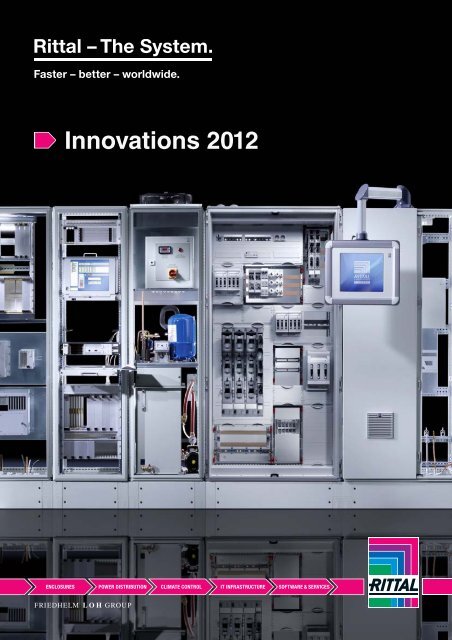
<strong>Innovations</strong> <strong>2012</strong>
Enclosures Page<br />
System enclosure SE 8............................................ 4 – 7<br />
TS IT rack .............................................................. 8 – 27<br />
Support arm system 60/120/180 ......................... 28 – 49<br />
Flex-Block base/plinth system............................. 50 – 55<br />
System accessories ............................................ 56 – 57<br />
Power distribution Page<br />
Bus-mounting fuse bases.................................... 60 – 64<br />
Component adaptors .......................................... 65 – 67<br />
Busbar systems for DC ....................................... 68 – 72<br />
NH slimline fuse-switch-disconnectors ............... 73 – 74<br />
RiLine/Ri4Power accessories .............................. 75 – 76<br />
Ri4Power .....................................................................77<br />
ISV distribution enclosures.................................. 78 – 87<br />
UPS – Power Modular Concept...................................90<br />
PDU – Power Distribution Unit............................. 91 – 95<br />
PSM – Power System Module.............................. 96 – 97<br />
Climate control Page<br />
LCP – Liquid Cooling Package for industry .... 100 – 101<br />
TopTherm EC fan-and-filter units ..............................102<br />
Air/water heat exchanger, door.................................103<br />
LCP – Liquid Cooling Package for IT .............. 106 – 107<br />
IT roof-mounted cooling units....................................108<br />
Climate control accessories ......................................109<br />
IT infrastructure Page<br />
Modular Safe level B .........................................110, 114<br />
DDC – Data Centre Container ...........................112, 115<br />
CMC III – Monitoring system .....................................116<br />
Software Page<br />
RiZone .......................................................................118<br />
RiTherm App .............................................................120<br />
EPLAN Pro Panel.......................................................121<br />
List of model numbers...............................................122<br />
Index..........................................................................123<br />
2
Efficiency through<br />
action<br />
Experience efficient system solutions across all industries.<br />
The future requirements of modern infrastructures demand efficient concepts.<br />
Rittal interprets these concepts individually, according to the specific application, and always tailored<br />
to each industry’s requirements. Experience Rittal's comprehensive approach to efficiency on various<br />
levels:<br />
Energy – With efficient cooling units and heat exchangers<br />
Material – Through innovative design procedures and by using alternative materials<br />
Time – With simple assembly of the new TS IT rack and SE 8 system enclosure<br />
Flexibility – With intelligent cross-system engineering<br />
3
THE TS 8 GOES SOLO:<br />
SYSTEM ENCLOSURE SE 8<br />
4
Construction<br />
� High stability thanks to a self-supporting,<br />
integral design<br />
� Minimal assembly work thanks to the<br />
extruded side panels<br />
� High protection category<br />
� Wide range of sheet steel and stainless<br />
steel versions for almost any application<br />
area<br />
Wide range of sizes<br />
� Enclosure depths of 400, 500 and<br />
600 mm<br />
� Enclosure widths ranging from 600 to<br />
1800 mm<br />
� Enclosure heights of 1800 and 2000 mm<br />
Installation options<br />
� Automatic potential equalisation<br />
� Optimum cable entry<br />
� Wide range of accessories with<br />
TS 8 system platform<br />
� Different base/plinth variants:<br />
Flex-Block, cable chamber or standard<br />
base/plinth in sheet steel or stainless<br />
steel<br />
5
System enclosure SE 8<br />
System accessories Page 56<br />
The system enclosure SE 8 is<br />
based on the TS 8 platform.<br />
System accessories for interior<br />
installation in the TS 8 design<br />
can be used without restrictions.<br />
Material:<br />
− Depending on the version:<br />
Sheet steel or 1.4301 stainless<br />
steel (AISI 304)<br />
− Enclosure: 1.5 mm<br />
− Door: 2.0 mm<br />
− Rear panel and gland plates:<br />
1.5 mm<br />
− Mounting plate: 3.0 mm,<br />
sheet steel, zinc-plated<br />
(for sheet steel and stainless<br />
steel enclosures)<br />
Sheet steel, width: 600 – 800 mm<br />
Sheet steel surface finish:<br />
− Enclosure, door (or double<br />
door) and rear panel:<br />
Dipcoat-primed, powdercoated<br />
on the outside,<br />
RAL 7035 textured paint<br />
− Gland plates: Zinc-plated<br />
Stainless steel surface finish:<br />
− Enclosure, rear panel,<br />
door or double door:<br />
Brushed, grain 400<br />
− Gland plates<br />
Protection category:<br />
IP 55 to IEC 60 529,<br />
complies with NEMA 12.<br />
Supply includes:<br />
− Enclosure with door(s)<br />
− With single-door enclosures:<br />
Door hinged on the right<br />
(can be changed to the left)<br />
− Mounting plate<br />
− Gland plates<br />
− Rear panel (in two pieces<br />
from a width of 1600 mm and<br />
more), screw-fastened<br />
Approvals:<br />
Available on the Internet.<br />
Detailed drawings:<br />
Available on the Internet.<br />
Width (B) mm Packs of 600 800 800 800 800<br />
Cat. 33,<br />
page<br />
Height (H) mm 1800 1800 2000 2000 2000<br />
Depth (T) mm 400 400 400 500 600<br />
Mounting plate width (F) mm 499 699 699 699 699<br />
Mounting plate height (G) mm 1696 1696 1896 1896 1896<br />
Model No. SE 1 5830.500 5831.500 5832.500 5833.500 5834.500<br />
Door(s)<br />
Base/plinth<br />
1 1 1 1 1<br />
Components front and rear<br />
Height 100 mm<br />
Height 200 mm<br />
1 set<br />
1 set<br />
8601.600<br />
8602.600<br />
8601.800<br />
8602.800<br />
8601.800<br />
8602.800<br />
8601.800<br />
8602.800<br />
8601.800<br />
8602.800<br />
543<br />
543<br />
Trim panels, sides<br />
Roof<br />
Height 100 mm<br />
Height 200 mm<br />
1 set<br />
1 set<br />
8601.040<br />
8602.040<br />
8601.040<br />
8602.040<br />
8601.040<br />
8602.040<br />
8601.050<br />
8602.050<br />
8601.060<br />
8602.060<br />
544<br />
544<br />
Eyebolts<br />
Rail systems<br />
4 4568.000 4568.000 4568.000 4568.000 4568.000 626<br />
Punched section with mounting flange,<br />
outer level<br />
4 8612.140 8612.140 8612.140 8612.150 8612.160 647<br />
Punched section with mounting flange,<br />
inner level<br />
4 8612.040 8612.040 8612.040 8612.050 8612.060 647<br />
Other rail systems, based on TS 8<br />
Base<br />
see Catalogue 33, from page 644<br />
Cable entry plate<br />
Accessories<br />
2 8800.060 8800.080 8800.080 8800.080 8800.080 701<br />
Cable clamp rails for cable clamps 2 4191.000 4192.000 4192.000 4192.000 4192.000 717<br />
Alternative lock systems see Catalogue 33, page 600<br />
6 Rittal <strong>Innovations</strong> <strong>2012</strong><br />
T<br />
B<br />
H<br />
F<br />
G
Sheet steel, width: 1000 – 1800 mm<br />
Stainless steel, width: 600 – 1200 mm<br />
Rittal <strong>Innovations</strong> <strong>2012</strong><br />
System enclosure SE 8<br />
Width (B) mm Packs of 1000 1200 1600 1200 1200 1200 1800<br />
Cat. 33,<br />
page<br />
Height (H) mm 1800 1800 1800 2000 2000 2000 2000<br />
Depth (T) mm 400 400 400 400 500 600 500<br />
Mounting plate width (F) mm 899 1099 1499 1099 1099 1099 1699<br />
Mounting plate height (G) mm 1696 1696 1696 1896 1896 1896 1896<br />
Model No. SE 1 5840.500 5841.500 5842.500 5843.500 5844.500 5845.500 5846.500<br />
Door(s)<br />
Base/plinth<br />
2 2 2 2 2 2 2<br />
Components front and rear<br />
Height 100 mm<br />
Height 200 mm<br />
1 set<br />
1 set<br />
8601.000<br />
8602.000<br />
8601.200<br />
8602.200<br />
8601.920<br />
8602.920<br />
8601.200<br />
8602.200<br />
8601.200<br />
8602.200<br />
8601.200<br />
8602.200<br />
8601.980<br />
8602.980<br />
543<br />
543<br />
Trim panels, sides<br />
Roof<br />
Height 100 mm<br />
Height 200 mm<br />
1 set<br />
1 set<br />
8601.040<br />
8602.040<br />
8601.040<br />
8602.040<br />
8601.040<br />
8602.040<br />
8601.040<br />
8602.040<br />
8601.050<br />
8602.050<br />
8601.060<br />
8602.060<br />
8601.050<br />
8602.050<br />
544<br />
544<br />
Eyebolts<br />
Rail systems<br />
4 4568.000 4568.000 4568.000 4568.000 4568.000 4568.000 4568.000 626<br />
Punched section with mounting flange,<br />
outer level<br />
4 8612.140 8612.140 8612.140 8612.140 8612.150 8612.160 8612.150 647<br />
Punched section with mounting flange,<br />
inner level<br />
4 8612.040 8612.040 8612.040 8612.040 8612.050 8612.060 8612.050 647<br />
Other rail systems, based on TS 8<br />
Base<br />
see Catalogue 33, from page 644<br />
Cable entry plate<br />
Accessories<br />
2 8800.100 8800.120 – 8800.120 8800.120 8800.120 – 701<br />
Cable clamp rails for cable clamps 2 4336.000 4196.000 4338.000 4196.000 4196.000 4196.000 4339.000 717<br />
Alternative lock systems see Catalogue 33, page 600<br />
Width (B) mm Packs of 600 600 800 800 1000 1200<br />
Cat. 33,<br />
page<br />
Height (H) mm 1600 1800 1800 2000 1800 2000<br />
Depth (T) mm 400 500 500 600 400 500<br />
Mounting plate width (F) mm 499 499 699 699 899 1099<br />
Mounting plate height (G) mm 1496 1696 1696 1896 1696 1896<br />
Model No. SE 5850.500 5851.500 5852.500 5853.500 5854.500 5855.500<br />
Door(s)<br />
Base/plinth<br />
1 1 1 1 1 2<br />
Components front and rear<br />
Height 100 mm<br />
Height 200 mm<br />
1 set<br />
1 set<br />
8701.600<br />
8702.600<br />
8701.600<br />
8702.600<br />
8701.800<br />
8702.800<br />
8701.800<br />
8702.800<br />
8701.000<br />
8702.000<br />
8701.200<br />
8702.200<br />
549<br />
549<br />
Trim panels<br />
Roof<br />
Height 100 mm<br />
Height 200 mm<br />
1 set<br />
1 set<br />
8701.040<br />
8702.040<br />
8701.050<br />
8702.050<br />
8701.050<br />
8702.050<br />
8701.060<br />
8702.060<br />
8701.040<br />
8702.040<br />
8701.050<br />
8702.050<br />
549<br />
549<br />
Eyebolts<br />
Rail systems<br />
4 4568.000 4568.000 4568.000 4568.000 4568.000 4568.000 626<br />
Punched section with mounting flange,<br />
outer level<br />
4 8612.140 8612.150 8612.150 8612.160 8612.140 8612.150 647<br />
Punched section with mounting flange,<br />
inner level<br />
4 8612.040 8612.050 8612.050 8612.060 8612.040 8612.050 647<br />
Other rail systems, based on TS 8<br />
Accessories<br />
see Catalogue 33, from page 644<br />
Cable clamp rails for cable clamps 2 4191.000 4191.000 4192.000 4192.000 4336.000 4196.000 717<br />
Alternative lock systems see Catalogue 33, page 602<br />
7
THE NEW TS IT RACK<br />
8
Fast and reliable<br />
� Fast – Loosen the 482.6 mm (19˝) quickrelease<br />
fastener, slide into the correct<br />
position, and latch<br />
� Reliable – Maximum load capacity<br />
up to 15,000 N<br />
Convenience in perfection<br />
� Interior installation – Side offset and<br />
alternative mounting dimensions easily<br />
achieved<br />
� Distance between levels – Direct determination<br />
with integral pitch pattern<br />
� U labelling – May be read from the front<br />
and rear<br />
Convincing door concept<br />
� Glazed door or vented door<br />
� Doors with 180° hinges and comfort<br />
handles, prepared for individual locks<br />
� Divided rear door for space-optimised<br />
positioning<br />
� Optimised air throughput – With open<br />
surface area 85% perforated<br />
Multi-functional roof<br />
� Brush strips for cable entry across the<br />
entire enclosure depth<br />
� Cable clamping directly behind the brush<br />
strip<br />
� Fan mounting plate with cut-out for active<br />
and passive climate control<br />
9
THE NEW TS IT RACK<br />
10
Tool-free installation<br />
� Tool-free installation of all slide rails,<br />
component shelves, telescopic slides<br />
and much more<br />
� Simply locate into the rear mounting<br />
angle, extend to the required size,<br />
and secure at the front<br />
Quick-assembly side panel<br />
� Divided side panel for simple one-man<br />
assembly<br />
� Locate side panel at the top, slot in<br />
at the bottom, snap shut – and it’s done.<br />
No screw-fastening required<br />
� Quick-release fasteners with integral<br />
lock additional with internal latch for<br />
increased security<br />
Built-in added value<br />
� Prepared for Dynamic Rack Control or<br />
cable management<br />
� Ready to use for space-saving, clip-on<br />
mounting of the Rittal PDU busbar; on<br />
both sides in the zero-U space between<br />
the mounting angle and side panel<br />
Maximum energy efficiency<br />
thanks to compartmentalisation<br />
with maximum flexibility<br />
� Fully suitable for rack/suite and room<br />
cooling<br />
� Variable termination at the sides<br />
with all-round brush strip<br />
� 6 U mounting space additionally integrated<br />
into the compartmentalisation<br />
11
TS IT<br />
Accessories Page 16 – 27<br />
Material:<br />
− Sheet steel<br />
− Glazed door: Single-pane<br />
safety glass, 3 mm<br />
Surface finish:<br />
− Enclosure frame, interior<br />
installation: Dipcoat-primed<br />
− Doors and roof: Dipcoatprimed,<br />
powder-coated<br />
With glazed door for rack climate control<br />
U Packs of 24 24 38 42 42 Page<br />
Width mm 800 800 800 800 800<br />
Height mm 1200 1200 1800 2000 2000<br />
Depth mm 800 1000 800 600 800<br />
Glazed aluminium door at the front (180°), with comfort handle<br />
for semi-cylinder and security lock 3524 E<br />
Sheet steel door at the rear (180°), with comfort handle<br />
for semi-cylinder and security lock 3524 E<br />
Colour:<br />
− Frame and enclosure panels:<br />
RAL 7035<br />
− Interior installation: RAL 9005<br />
Supply includes:<br />
Product-specific supply scope,<br />
see table.<br />
Sheet steel door at the rear (180°), vertically divided, with comfort<br />
handle for semi-cylinder and security lock 3524 E<br />
482.6 mm (19˝) mounting level at the front and rear, on depth stays<br />
with quick-release fasteners, depth-variable<br />
Roof plate, multi-piece, removable, with side cable entry in the depth<br />
and covered cut-out for fan mounting plate<br />
Load capacity of the 482.6 mm<br />
(19˝) mounting level:<br />
15,000 N<br />
Distance between levels<br />
as delivered:<br />
− Depth < 800: 545 mm<br />
− Depth ><br />
1000: 745 mm<br />
Approvals:<br />
UL/cUL<br />
Detailed drawings:<br />
Available on the Internet.<br />
1 � � � � �<br />
1 � � – – –<br />
1 – – � � �<br />
2 � � � � �<br />
1 � � � � 1) �<br />
Model No. DK 1 5503.120 5504.120 5505.120 5506.120 5507.120<br />
Included with the supply, not pre-installed<br />
Spacers for passive cooling 4 � � � � �<br />
Earthing set with central earthing point 1 set � � � � �<br />
Multi-tooth screws M5, cage nuts M5, conductive<br />
Accessories<br />
50 � � � � �<br />
Side panels<br />
2-part<br />
1-part<br />
1<br />
2<br />
–<br />
8175.235<br />
–<br />
8176.235<br />
2 x 5501.000 2 x 5501.010 2 x 5501.020<br />
– – –<br />
20<br />
5672) Base mount 2 5501.310 5501.320 5501.310 5501.300 5501.310 20<br />
Gland plates, modular see from page 16<br />
Base/plinth see Catalogue 33, page 542<br />
Fan mounting plate for TS IT including thermostat 1 5502.020 5502.020 5502.020 5502.010 5502.020 21<br />
Air baffle plate 1 set – – – 5501.815 5501.815 26<br />
Cable route 1 – – – 5502.120 5502.120 23<br />
Cable duct 1 – – – 5502.105 5502.105 22<br />
Component shelves see from page 21<br />
Slide rails see from page 26<br />
Cable clamp rails, C rails, punched sections with mounting flanges see Catalogue 33, from page 644<br />
Cable shunting ring see Catalogue 33, from page 724<br />
Cable management panel see page 24<br />
Power distribution unit PDU<br />
� Included with the supply.<br />
see page 91<br />
1) Cable entry, rear. 2) See Catalogue 33.<br />
12 Rittal <strong>Innovations</strong> <strong>2012</strong>
With glazed door for rack climate control<br />
U Packs of 42 42 42 42 47<br />
Width mm 600 800 600 800 800<br />
Height mm 2000 2000 2000 2000 2200<br />
Depth mm 1000 1000 1200 1200 800<br />
Glazed aluminium door at the front (180°), with comfort handle<br />
for semi-cylinder and security lock 3524 E<br />
Sheet steel door at the rear (180°), vertically divided, with comfort<br />
handle for semi-cylinder and security lock 3524 E<br />
482.6 mm (19˝) mounting level at the front and rear, on depth stays<br />
with quick-release fasteners, depth-variable<br />
Roof plate, multi-piece, removable, with side cable entry in the depth<br />
and covered cut-out for fan mounting plate<br />
Rittal <strong>Innovations</strong> <strong>2012</strong><br />
1 � � � � �<br />
1 � � � � �<br />
4 � � � � �<br />
1 � � � � �<br />
Model No. DK 1 5508.120 5509.120 5510.120 5511.120 5512.120<br />
TS IT<br />
Included with the supply, not pre-installed<br />
Spacers for passive cooling 4 � � � � �<br />
Earthing set with central earthing point 1 set � � � � �<br />
Multi-tooth screws M5, cage nuts M5, conductive<br />
Accessories<br />
50 � � � � �<br />
Side panels, 2-part 1 2 x 5501.030 2 x 5501.030 2 x 5501.040 2 x 5501.040 2 x 5501.050 20<br />
Base mount 2 5501.320 5501.320 5501.350 5501.350 5501.310 20<br />
Gland plates, modular see from page 16<br />
Base/plinth see Catalogue 33, page 542<br />
Fan mounting plate for TS IT including thermostat 1 5502.010 5502.020 5502.010 5502.020 5502.020 21<br />
Air baffle plate 1 set 5501.805 5501.815 5501.805 5501.815 5501.835 26<br />
Cable route 1 5502.120 5502.120 5502.120 5502.120 5502.120 23<br />
Cable duct 1 – 5502.105 – 5502.105 5502.145 22<br />
Component shelves see from page 21<br />
Slide rails see from page 26<br />
Cable clamp rails, C rails, punched sections with mounting flanges see Catalogue 33, from page 644<br />
Cable shunting ring see Catalogue 33, from page 724<br />
Cable management panel see page 24<br />
Power distribution unit PDU<br />
� Included with the supply.<br />
see page 91<br />
Rittal Germany<br />
RITTAL GmbH & Co. KG<br />
Postfach 1662 � D-35726 Herborn<br />
Phone: +49(0)2772 505-0<br />
Fax: +49(0)2772 505-2319<br />
E-mail: info@rittal.de � www.rittal.com<br />
13
TS IT<br />
Accessories Page 16 – 27<br />
Material:<br />
Sheet steel<br />
Surface finish:<br />
− Enclosure frame,<br />
interior installation:<br />
Dipcoat-primed<br />
− Doors and roof: Dipcoatprimed,<br />
powder-coated<br />
Colour:<br />
− Frame and enclosure panels:<br />
RAL 7035<br />
− Interior installation: RAL 9005<br />
Supply includes:<br />
Product-specific supply scope,<br />
see table.<br />
With vented door for room climate control<br />
U Packs of 24 42 42 42 42 Page<br />
Width mm 800 600 800 600 800<br />
Height mm 1200 2000 2000 2000 2000<br />
Depth mm 1000 1000 1000 1200 1200<br />
Sheet steel door, vented 1) , at the front (180°), with comfort handle<br />
for semi-cylinder and security lock 3524 E<br />
Sheet steel door, vented 1) , at the rear (180°), with comfort handle<br />
for semi-cylinder and security lock 3524 E<br />
Sheet steel door, vented 1) , at the rear (180°), vertically divided,<br />
with comfort handle for semi-cylinder and security lock 3524 E<br />
482.6 mm (19˝) mounting level at the front and rear, on depth stays<br />
with quick-release fasteners, depth-variable<br />
Roof plate, multi-piece, removable, with side cable entry in the depth<br />
and covered cut-out for fan mounting plate<br />
Load capacity of the 482.6 mm<br />
(19˝) mounting level:<br />
15,000 N<br />
Distance between levels<br />
as delivered:<br />
745 mm<br />
Approvals:<br />
UL/cUL<br />
Detailed drawings:<br />
Available on the Internet.<br />
1 � � � � �<br />
1 � – – – –<br />
1 – � � � �<br />
2 � � � � �<br />
1 � � � � �<br />
Model No. DK 1 5504.110 5508.110 5509.110 5510.110 5511.110<br />
Included with the supply, not pre-installed<br />
Spacers for passive cooling 4 � � � � �<br />
Earthing set with central earthing point 1 set � � � � �<br />
Multi-tooth screws M5, cage nuts M5, conductive<br />
Accessories<br />
50 � � � � �<br />
Side panels<br />
2-part<br />
1-part<br />
1<br />
2<br />
–<br />
8176.235<br />
2 x 5501.030 2 x 5501.030 2 x 5501.040 2 x 5501.040<br />
– – – –<br />
20<br />
5672) Base mount 2 5501.320 5501.320 5501.320 5501.350 5501.350 20<br />
Gland plates, modular see from page 16<br />
Base/plinth see Catalogue 33, page 542<br />
Fan mounting plate for TS IT including thermostat 1 5502.020 5502.010 5502.020 5502.010 5502.020 21<br />
Air baffle plate 1 set – 5501.805 5501.815 5501.805 5501.815 26<br />
Cable route 1 – 5502.120 5502.120 5502.120 5502.120 23<br />
Cable duct 1 – – 5502.105 – 5502.105 22<br />
Component shelves see from page 21<br />
Slide rails see from page 26<br />
Cable clamp rails, C rails, punched sections with mounting flanges see Catalogue 33, from page 644<br />
Cable shunting ring see Catalogue 33, from page 724<br />
Cable management panel see page 24<br />
Power distribution unit PDU<br />
� Included with the supply.<br />
see page 91<br />
1) Vented surface area approx. 85% perforated. 2) See Catalogue 33.<br />
14 Rittal <strong>Innovations</strong> <strong>2012</strong>
With vented door for room climate control<br />
Rittal <strong>Innovations</strong> <strong>2012</strong><br />
TS IT<br />
U Packs of 47 47 47 47 Page<br />
Width mm 600 800 600 800<br />
Height mm 2200 2200 2200 2200<br />
Depth mm 1000 1000 1200 1200<br />
Sheet steel door, vented 1) , at the front (180°), with comfort handle<br />
for semi-cylinder and security lock 3524 E<br />
Sheet steel door, vented 1) , at the rear (180°), vertically divided,<br />
with comfort handle for semi-cylinder and security lock 3524 E<br />
482.6 mm (19˝) mounting level at the front and rear, on depth stays<br />
with quick-release fasteners, depth-variable<br />
Roof plate, multi-piece, removable, with side cable entry in the depth<br />
and covered cut-out for fan mounting plate<br />
1 � � � �<br />
1 � � � �<br />
2 � � � �<br />
1 � � � �<br />
Model No. DK 1 5513.110 5514.110 5515.110 5516.110<br />
Included with the supply, not pre-installed<br />
Spacers for passive cooling 4 � � � �<br />
Earthing set with central earthing point 1 set � � � �<br />
Multi-tooth screws M5, cage nuts M5, conductive<br />
Accessories<br />
50 � � � �<br />
Side panels, 2-part 1 2 x 5501.060 2 x 5501.060 2 x 5501.070 2 x 5501.070 20<br />
Base mount 2 5501.320 5501.320 5501.350 5501.350 20<br />
Gland plates, modular see from page 16<br />
Base/plinth see Catalogue 33, page 542<br />
Fan mounting plate for TS IT including thermostat 1 5502.010 5502.020 5502.010 5502.020 21<br />
Air baffle plate 1 set 5501.825 5501.835 5501.825 5501.835 26<br />
Cable route 1 5502.120 5502.120 5502.120 5502.120 23<br />
Cable duct 1 – 5502.145 – 5502.145 22<br />
Component shelves see from page 21<br />
Slide rails see from page 26<br />
Cable clamp rails, C rails, punched sections with mounting flanges see Catalogue 33, from page 644<br />
Cable shunting ring see Catalogue 33, from page 724<br />
Cable management panel see page 24<br />
Power distribution unit PDU<br />
� Included with the supply.<br />
see page 91<br />
1) Vented surface area approx. 85% perforated.<br />
Rittal Great Britain<br />
RITTAL Limited<br />
Braithwell Way � Hellaby Industrial Estate<br />
Hellaby � Rotherham � S Yorks S66 8QY<br />
Phone: +44 (0) 1709 704000<br />
Fax: +44 (0) 1709 701217<br />
E-mail: information@rittal.co.uk<br />
www.rittal.co.uk<br />
15
TS IT<br />
Accessories<br />
Gland plate<br />
for TS IT<br />
Potential equalisation is provided via assembly<br />
components and earthing points.<br />
� Gland plate set<br />
To conceal the entire base opening.<br />
� Gland plate modules<br />
Select suitable gland plates depending on the<br />
application.<br />
For enclosure depth 600 mm<br />
Material:<br />
Sheet steel<br />
Surface finish:<br />
Zinc-plated<br />
Supply includes:<br />
Assembly parts.<br />
Accessories:<br />
Clips for gland plates,<br />
see Catalogue 33, page 559.<br />
For enclosure width mm<br />
A Gland plate set Packs of<br />
Required<br />
packs<br />
600 800<br />
Model No. DK<br />
Gland plate, solid with sliding panel, multi-piece 1 set 1 – 5502.510<br />
Gland plate modules Packs of<br />
Required<br />
packs<br />
For enclosure width mm<br />
600 800<br />
B 1 module plate as selected Model No. DK<br />
Gland plate, depth 150 mm 1 1 5001.218 5001.219<br />
Sliding panel, depth 150 mm 1 1 5001.239 5001.240<br />
Module<br />
plate,<br />
depth<br />
237.5 mm<br />
Vented with airflow regulator<br />
7825.366 7825.386<br />
Cable entry with brush strip 7825.361 7825.381<br />
Vented 1 1 7825.360 7825.380<br />
Cable entry with brush strip, super-airtight 7825.367 7825.387<br />
Cable entry, side – 7825.388<br />
C Cable entry, rear or front Model No. DK<br />
Gland plate, depth 100 mm 1 2 5001.214 5001.215<br />
Sliding panel, depth 150 mm 1 2 5001.239 5001.240<br />
Self-adhesive foam cable clamp strip 3 m 1 2573.000 2573.000<br />
D Cable entry, centre Model No. DK<br />
Gland plate, depth 100 mm 1 2 5001.214 5001.215<br />
Sliding panel, depth 150 mm 1 2 5001.239 5001.240<br />
Section for cable entry, centre 1 set 1 8802.060 8802.080<br />
A<br />
5<br />
1<br />
2<br />
1 Gland plate, depth 250 mm<br />
2 Gland plate, depth 150 mm<br />
3 Gland plate, depth 100 mm<br />
4 Gland plate, depth 50 mm<br />
5 Sliding panel, depth 150 mm<br />
6 Module plate, depth 237.5 mm<br />
7 Foam rubber cable clamp strip<br />
8 Section for cable entry, centre<br />
B<br />
16 Rittal <strong>Innovations</strong> <strong>2012</strong><br />
6<br />
2<br />
5<br />
C<br />
7<br />
5<br />
3<br />
5<br />
D<br />
3<br />
5<br />
3<br />
5<br />
8<br />
Also required:<br />
Base mount, see page 20.
For enclosure depth 800 mm<br />
Rittal <strong>Innovations</strong> <strong>2012</strong><br />
TS IT<br />
Accessories<br />
For enclosure width mm<br />
A Gland plate set Packs of<br />
Required<br />
packs<br />
600 800<br />
Model No. DK<br />
Gland plate, solid with sliding panel, multi-piece 1 set 1 – 5502.530<br />
Gland plate modules Packs of<br />
Required<br />
packs<br />
For enclosure width mm<br />
600 800<br />
B 1 module plate as selected Model No. DK<br />
Gland plate, depth 250 mm 1 1 5001.222 5001.223<br />
Gland plate, depth 100 mm 1 1 5001.214 5001.215<br />
Sliding panel, depth 150 mm 1 1 5001.239 5001.240<br />
Module<br />
plate,<br />
depth<br />
237.5 mm<br />
Vented with airflow regulator<br />
7825.366 7825.386<br />
Cable entry with brush strip 7825.361 7825.381<br />
Vented 1 1 7825.360 7825.380<br />
Cable entry with brush strip, super-airtight 7825.367 7825.387<br />
Cable entry, side – 7825.388<br />
C 2 module plates as selected Model No. DK<br />
Gland plate, depth 100 mm 1 1 5001.218 5001.219<br />
Sliding panel, depth 150 mm 1 1 5001.239 5001.240<br />
Module<br />
plate,<br />
depth<br />
237.5 mm<br />
Vented with airflow regulator<br />
7825.366 7825.386<br />
Cable entry with brush strip 7825.361 7825.381<br />
Vented 1 2 7825.360 7825.380<br />
Cable entry with brush strip, super-airtight 7825.367 7825.387<br />
Cable entry, side – 7825.388<br />
D Cable entry, rear or front Model No. DK<br />
Gland plate, depth 250 mm 1 1 5001.222 5001.223<br />
Gland plate, depth 150 mm 1 1 5001.218 5001.219<br />
Sliding panel, depth 150 mm 1 2 5001.239 5001.240<br />
Self-adhesive foam cable clamp strip 3 m 1 2573.000 2573.000<br />
E Cable entry, centre Model No. DK<br />
Gland plate, depth 250 mm 1 1 5001.222 5001.223<br />
Gland plate, depth 150 mm 1 1 5001.218 5001.219<br />
Sliding panel, depth 150 mm 1 2 5001.239 5001.240<br />
Section for cable entry, centre 1 set 1 8802.060 8802.080<br />
A<br />
5<br />
1<br />
1<br />
3<br />
1 Gland plate, depth 250 mm<br />
2 Gland plate, depth 150 mm<br />
3 Gland plate, depth 100 mm<br />
4 Gland plate, depth 50 mm<br />
5 Sliding panel, depth 150 mm<br />
6 Module plate, depth 237.5 mm<br />
7 Foam rubber cable clamp strip<br />
8 Section for cable entry, centre<br />
B<br />
6<br />
3<br />
1<br />
5<br />
C<br />
6<br />
5<br />
3<br />
6<br />
D<br />
7<br />
5<br />
2<br />
1<br />
5<br />
Also required:<br />
Base mount, see page 20.<br />
E<br />
2<br />
5<br />
8<br />
1<br />
5<br />
17
TS IT<br />
Accessories<br />
For enclosure depth 1000 mm<br />
For enclosure width mm<br />
A Gland plate set Packs of<br />
Required<br />
packs<br />
600 800<br />
Model No. DK<br />
Gland plate, solid with sliding panel, multi-piece 1 set 1 5502.540 5502.550<br />
Gland plate modules Packs of<br />
Required<br />
packs<br />
For enclosure width mm<br />
600 800<br />
B 1 module plate as selected Model No. DK<br />
Gland plate, depth 250 mm 1 2 5001.222 5001.223<br />
Gland plate, depth 50 mm 1 1 5001.210 5001.211<br />
Sliding panel, depth 150 mm 1 1 5001.239 5001.240<br />
Module<br />
plate,<br />
depth<br />
237.5 mm<br />
Vented with airflow regulator<br />
7825.366 7825.386<br />
Cable entry with brush strip 7825.361 7825.381<br />
Vented 1 1 7825.360 7825.380<br />
Cable entry with brush strip, super-airtight 7825.367 7825.387<br />
Cable entry, side – 7825.388<br />
C 2 module plates as selected Model No. DK<br />
Gland plate, depth 250 mm 1 1 5001.222 5001.223<br />
Gland plate, depth 100 mm 1 1 5001.214 5001.215<br />
Sliding panel, depth 150 mm 1 1 5001.239 5001.240<br />
Module<br />
plate,<br />
depth<br />
237.5 mm<br />
Vented with airflow regulator<br />
7825.366 7825.386<br />
Cable entry with brush strip 7825.361 7825.381<br />
Vented 1 2 7825.360 7825.380<br />
Cable entry with brush strip, super-airtight 7825.367 7825.387<br />
Cable entry, side – 7825.388<br />
D Cable entry, rear or front Model No. DK<br />
Gland plate, depth 250 mm 1 2 5001.222 5001.223<br />
Gland plate, depth 100 mm 1 1 5001.214 5001.215<br />
Sliding panel, depth 150 mm 1 2 5001.239 5001.240<br />
Self-adhesive foam cable clamp strip 3 m 1 2573.000 2573.000<br />
E Cable entry, centre Model No. DK<br />
Gland plate, depth 250 mm 1 2 5001.222 5001.223<br />
Gland plate, depth 100 mm 1 1 5001.214 5001.215<br />
Sliding panel, depth 150 mm 1 2 5001.239 5001.240<br />
Section for cable entry, centre 1 set 1 8802.060 8802.080<br />
A<br />
5<br />
1<br />
1<br />
2<br />
2<br />
1 Gland plate, depth 250 mm<br />
2 Gland plate, depth 150 mm<br />
3 Gland plate, depth 100 mm<br />
4 Gland plate, depth 50 mm<br />
5 Sliding panel, depth 150 mm<br />
6 Module plate, depth 237.5 mm<br />
7 Foam rubber cable clamp strip<br />
8 Section for cable entry, centre<br />
B<br />
18 Rittal <strong>Innovations</strong> <strong>2012</strong><br />
6<br />
1<br />
4<br />
1<br />
5<br />
C<br />
6<br />
1<br />
5<br />
3<br />
6<br />
D<br />
7<br />
5<br />
1<br />
2<br />
1<br />
5<br />
Also required:<br />
Base mount, see page 20.<br />
E<br />
2<br />
1<br />
5<br />
8<br />
1<br />
5
For enclosure depth 1200 mm<br />
Rittal <strong>Innovations</strong> <strong>2012</strong><br />
TS IT<br />
Accessories<br />
For enclosure width mm<br />
A Gland plate set Packs of<br />
Required<br />
packs<br />
600 800<br />
Model No. DK<br />
Gland plate, solid with sliding panel, multi-piece 1 set 1 5502.560 5502.570<br />
Gland plate modules Packs of<br />
Required<br />
packs<br />
For enclosure width mm<br />
600 800<br />
B 1 module plate as selected Model No. DK<br />
Gland plate, depth 250 mm 1 3 5001.222 5001.223<br />
Sliding panel, depth 150 mm 1 1 5001.239 5001.240<br />
Module<br />
plate,<br />
depth<br />
237.5 mm<br />
Vented with airflow regulator<br />
7825.366 7825.386<br />
Cable entry with brush strip 7825.361 7825.381<br />
Vented 1 1 7825.360 7825.380<br />
Cable entry with brush strip, super-airtight 7825.367 7825.387<br />
Cable entry, side – 7825.388<br />
C 2 module plates as selected Model No. DK<br />
Gland plate, depth 250 mm 1 2 5001.222 5001.223<br />
Gland plate, depth 50 mm 1 1 5001.210 5001.211<br />
Sliding panel, depth 150 mm 1 1 5001.239 5001.240<br />
Module<br />
plate,<br />
depth<br />
237.5 mm<br />
Vented with airflow regulator<br />
7825.366 7825.386<br />
Cable entry with brush strip 7825.361 7825.381<br />
Vented 1 2 7825.360 7825.380<br />
Cable entry with brush strip, super-airtight 7825.367 7825.387<br />
Cable entry, side – 7825.388<br />
D Cable entry, rear or front Model No. DK<br />
Gland plate, depth 250 mm 1 2 5001.222 5001.223<br />
Gland plate, depth 150 mm 1 3 5001.218 5001.219<br />
Sliding panel, depth 150 mm 1 1 5001.239 5001.240<br />
Self-adhesive foam cable clamp strip 3 m 1 2573.000 2573.000<br />
E Cable entry, centre Model No. DK<br />
Gland plate, depth 250 mm 1 2 5001.222 5001.223<br />
Gland plate, depth 150 mm 1 3 5001.218 5001.218<br />
Sliding panel, depth 150 mm 1 1 5001.239 5001.240<br />
Section for cable entry, centre 1 set 1 8802.060 8802.080<br />
A<br />
5<br />
1<br />
1<br />
1<br />
1<br />
1 Gland plate, depth 250 mm<br />
2 Gland plate, depth 150 mm<br />
3 Gland plate, depth 100 mm<br />
4 Gland plate, depth 50 mm<br />
5 Sliding panel, depth 150 mm<br />
6 Module plate, depth 237.5 mm<br />
7 Foam rubber cable clamp strip<br />
8 Section for cable entry, centre<br />
B<br />
6<br />
1<br />
1<br />
C<br />
6<br />
1<br />
5<br />
1<br />
2<br />
1<br />
4<br />
2<br />
5<br />
6<br />
2<br />
D<br />
7<br />
5<br />
1<br />
1<br />
Also required:<br />
Base mount, see page 20.<br />
E<br />
1<br />
1<br />
8<br />
5<br />
2<br />
2<br />
2<br />
19
TS IT<br />
Accessories<br />
Base mount<br />
To accommodate gland plate modules.<br />
� Tool-free mounting or screw-fastening<br />
� Easily retroffitted and combined with stabiliser<br />
Material:<br />
Sheet steel<br />
Surface finish:<br />
Spray-finished<br />
Colour:<br />
RAL 7035<br />
Supply includes:<br />
2 mounting rails including assembly parts.<br />
Side panel, divided<br />
� Easy handling and tool-free assembly<br />
� Quick-release fastener including security lock<br />
3524 E<br />
� Internal latch included<br />
(no key required)<br />
� Lock with chassis, cable clamp rail may be<br />
top-mounted on the outer mounting level<br />
� Suitable for IT climate control and rack<br />
extinguishing<br />
Material:<br />
Sheet steel<br />
Surface finish:<br />
Spray-finished<br />
Colour:<br />
RAL 7035<br />
Supply includes:<br />
− 1 console<br />
− 1 pedestal<br />
− Earth conductor<br />
− Assembly parts<br />
Tubular door frame<br />
for rear door, vertically divided, solid<br />
Material:<br />
Sheet steel<br />
Surface finish:<br />
Zinc-plated<br />
Supply includes:<br />
Assembly parts.<br />
For enclosure depth<br />
mm<br />
Packs of Model No. DK<br />
600 2 5501.300<br />
800 2 5501.310<br />
1000 2 5501.320<br />
1200 2 5501.350<br />
For enclosures<br />
Height mm Depth mm<br />
Packs of Model No. DK<br />
1800 800 1 5501.000<br />
2000 600 1 5501.010<br />
2000 800 1 5501.020<br />
2000 1000 1 5501.030<br />
2000 1200 1 5501.040<br />
2200 800 1 5501.050<br />
2200 1000 1 5501.060<br />
2200 1200 1 5501.070<br />
For enclosures<br />
Width mm Height mm<br />
Packs of Model No. DK<br />
600 2000 1 set 5501.200<br />
800 2000 1 set 5501.210<br />
Note:<br />
Required for use of the automatic door opener.<br />
20 Rittal <strong>Innovations</strong> <strong>2012</strong>
Fan mounting plate<br />
For active ventilation of the TS IT. For use in the<br />
cut-out integrated into the roof plate. The unit may<br />
optionally be extended with additional fans.<br />
Technical specifications for one fan:<br />
Fan expansion kit, DK 7980.000,<br />
see Catalogue 33, page 404.<br />
Technical specifications of thermostat:<br />
− Rated operating voltage: 250 V<br />
− Temperature range: +5 °C to +55 °C<br />
Colour:<br />
RAL 7035<br />
W x D<br />
mm<br />
Rittal <strong>Innovations</strong> <strong>2012</strong><br />
Number of<br />
pre-wired fans<br />
TS IT<br />
Accessories<br />
Supply includes:<br />
− Fan unit<br />
− 2 fans<br />
− 1 thermostat<br />
− Open connection cable<br />
− Assembly parts<br />
Note:<br />
Connection via distributor box or country-specific<br />
connector.<br />
Accessories:<br />
Fan expansion kit,<br />
see Catalogue 33, page 404.<br />
Possible number<br />
of fans<br />
800 x 600, 600 x 1000, 600 x 1200 2 3<br />
Model No. DK<br />
5502.010<br />
800 x 800, 800 x 1000, 800 x 1200 2 6 5502.020<br />
Component shelf, 2 U,<br />
static installation<br />
482.6 mm (19˝)<br />
For mounting between 482.6 mm (19˝) mounting<br />
angles.<br />
Load capacity:<br />
25 kg surface load, static<br />
Material:<br />
Sheet steel<br />
Surface finish:<br />
Spray-finished<br />
Colour:<br />
RAL 9005<br />
Supply includes:<br />
Assembly parts.<br />
Component shelf,<br />
depth-variable<br />
482.6 mm (19˝)<br />
for TS IT, L-shaped mounting angles,<br />
482.6 mm (19˝) mounting frame<br />
For static installation between two 482.6 mm (19˝)<br />
mounting levels.<br />
� Depth-variable to adapt to individual distances<br />
between levels<br />
� Tool-free, time-saving one-man assembly<br />
Material:<br />
Sheet steel<br />
Surface finish:<br />
Spray-finished<br />
Colour:<br />
RAL 9005<br />
Supply includes:<br />
Assembly parts.<br />
Component shelf depth<br />
mm<br />
Packs of Model No. DK<br />
250 1 set 5501.615<br />
400 1 set 5501.625<br />
Distance<br />
between<br />
levels<br />
mm<br />
Load<br />
capacity,<br />
static<br />
kg<br />
Height<br />
U<br />
Packs<br />
of<br />
Model No.<br />
DK<br />
400 – 600 50 1<br />
/2 1 set 5501.655<br />
600 – 900 50 1<br />
/2 1 set 5501.665<br />
400 – 600 100 1 1 set 5501.695<br />
600 – 900 100 1 1 set 5501.705<br />
21
TS IT<br />
Accessories<br />
Component shelf, pull-out<br />
482.6 mm (19˝)<br />
for TS IT, L-shaped mounting angles,<br />
482.6 mm (19˝) mounting frame<br />
For mounting between two 482.6 mm (19˝) mounting<br />
angles.<br />
� Depth-variable to adapt to individual distances<br />
between levels<br />
� Tool-free, time-saving one-man assembly from<br />
the enclosure front<br />
� Self-locking<br />
� Fully extendible<br />
Material:<br />
Sheet steel<br />
Surface finish:<br />
Spray-finished<br />
Colour:<br />
RAL 9005<br />
Supply includes:<br />
− Installation kit<br />
− Telescopic slide with mounting kit<br />
− Assembly parts<br />
Cable duct<br />
for TS IT, DK-TS, TE<br />
� High packing density due to U-based cable<br />
routing<br />
� Removable duct cover hinged on both sides<br />
� Optional cable holders may be used<br />
(DK 7827.330, see Catalogue 33, page 728)<br />
� Suitable for back-to-back baying<br />
� Simple assembly with tool-free quick-release<br />
fastening<br />
� Alternatively suitable for screw-fastening<br />
Material:<br />
Sheet steel, plastic UL 94-V0<br />
Colour:<br />
RAL 9005<br />
Supply includes:<br />
Cover and assembly parts.<br />
Cable finger 6 U<br />
for TS IT<br />
� For U-based cable routing<br />
� Simple, tool-free assembly<br />
� Cable routing possible in conjunction with<br />
air baffle plates<br />
Material:<br />
Plastic, UL 94-V0<br />
Colour:<br />
RAL 9005<br />
Distance<br />
between<br />
levels<br />
mm<br />
Load<br />
capacity,<br />
static<br />
kg<br />
22 Rittal <strong>Innovations</strong> <strong>2012</strong><br />
Height<br />
U<br />
Depth<br />
mm<br />
Packs<br />
of<br />
Model No.<br />
DK<br />
400 – 600 50 1 500 1 set 5501.675<br />
600 – 900 50 1 700 1 set 5501.685<br />
400 – 600 100 11 /2 500 1 set 5501.715<br />
600 – 900 100 11 /2 700 1 set 5501.725<br />
For enclosure<br />
height<br />
mm<br />
U Packs of Model No. DK<br />
2000 36 1 5502.105<br />
2200 42 1 5502.145<br />
Packs of Model No. DK<br />
14 5502.115
Cable manager<br />
� For system-compatible cable deflection while<br />
complying with minimal bending radii and to<br />
accommodate surplus cables and excess<br />
length. The elements may optionally be used<br />
individually or in combination for cable routing.<br />
They may be combined into semi-circular or<br />
circular elements.<br />
� Supports use on corners and edges to allow<br />
protected cable routing around them.<br />
� Mounting clips for use above the arc hold the<br />
routed cables back within the elements. The<br />
elements are also bayable in an axial direction<br />
to allow U-based cable routing to the mounting<br />
level, or channelling of the cable sections.<br />
Material:<br />
Plastic, UL 94-V0<br />
Colour:<br />
RAL 9005<br />
Supply includes:<br />
Mounting clips and assembly parts.<br />
Cable route<br />
� For cable clamping and routing with network<br />
and server applications<br />
� Mounting across the entire depth with 800 mm<br />
width, mounting only behind the second<br />
482.6 mm (19˝) pair of mounting angles with<br />
600 mm width<br />
� Tool-free quick assembly<br />
� Alternatively suitable for screw-fastening<br />
� Multi-functional punchings for cable management<br />
accessories<br />
Material:<br />
Sheet steel<br />
Colour:<br />
RAL 9005<br />
Nylon tape supports<br />
� For simple, fast cable attachment<br />
� Tool-free mounting in the system punchings<br />
with 10.5 x 12.5 mm, with a quarter rotation<br />
� Direct use on the horizontal TS section, on the<br />
support strips and mounting angles of the<br />
482.6 mm (19˝) interior installation on the cable<br />
route or on punched sections with mounting<br />
flanges.<br />
� Length of nylon tape: 400 mm<br />
Material:<br />
Plastic<br />
Supply includes:<br />
10 supports including nylon tape<br />
Rittal <strong>Innovations</strong> <strong>2012</strong><br />
TS IT<br />
Accessories<br />
Packs of Model No. DK<br />
20 5502.405<br />
44<br />
Height mm Packs of Model No. DK<br />
2000 – 2200 1 5502.120<br />
Accessories:<br />
− Cable ties, nylon tape,<br />
see Catalogue 33, page 720<br />
− Shunting rings,<br />
see Catalogue 33, from page 723<br />
− Cable routing bars,<br />
see Catalogue 33, page 727<br />
75<br />
50<br />
50<br />
75<br />
Packs of Model No. DK<br />
10 5502.155<br />
23
TS IT<br />
Accessories<br />
System supports<br />
for cable routes<br />
for TS IT<br />
The depth-variable support system may be<br />
attached to all 800 – 1200 mm deep TS enclosures<br />
with external screw-fastening of the roof<br />
plate. The integral system punchings, for screws<br />
or cage nuts, support the attachment of most<br />
common cable route systems.<br />
� May be combined with TS IT fan mounting plate<br />
� In combination with punched rail, suitable for<br />
accommodating additional cable guide rails or<br />
pipelines<br />
Material:<br />
Sheet steel<br />
Surface finish:<br />
Powder-coated<br />
Colour:<br />
RAL 7035<br />
Cable management panel<br />
482.6 mm (19˝)<br />
For horizontal management of the patch cables,<br />
with 5 cable shunting rings.<br />
Material:<br />
− Panel: Sheet steel<br />
− Ring: Steel<br />
Surface finish:<br />
Ring: Zinc-plated<br />
Colour:<br />
RAL 9005<br />
Cable management panel<br />
with cable routing bars<br />
482.6 mm (19˝)<br />
For horizontal management of the patch cables<br />
with cable routing bars. Opening the individual<br />
cable routing bars allows user-friendly modification<br />
and extension of the cabling.<br />
Material:<br />
− Panel: Sheet steel, spray-finished<br />
− Cable routing bars: Plastic<br />
Colour:<br />
− Panel: RAL 9005<br />
− Cable routing bars: Black<br />
Packs of Model No. DK<br />
1 7831.472<br />
Accessories:<br />
− Metal multi-tooth screws 5.5 x 13 mm,<br />
SZ 2486.500, see Catalogue 33, page 666.<br />
− Cage nuts M6, TS 8800.340,<br />
see Catalogue 33, page 665.<br />
U Ring size mm Packs of Model No. DK<br />
1 43 x 55 1 5502.205<br />
1 43 x 105 1 7257.005<br />
2 85 x 125 1 7257.105<br />
24 Rittal <strong>Innovations</strong> <strong>2012</strong><br />
U<br />
Bar depth<br />
mm<br />
No. of<br />
bars/<br />
U<br />
Packs<br />
of<br />
Model No.<br />
DK<br />
1 approx. 80 5 1 5502.225
Cable management panel, 2 U<br />
482.6 mm (19˝)<br />
The cable routing chamber has cut-outs from<br />
above, into which the patch cables can be<br />
inserted. The cable management panel is<br />
equipped with a flap and quick-release fasteners<br />
at the front, for optimum access to the cables.<br />
From the rear, the cables can be inserted via a<br />
cut-out with brush strips. With accommodation<br />
facility for cable clamp straps DK 7610.000 or<br />
DK 7611.000.<br />
Material:<br />
Sheet steel<br />
Colour:<br />
RAL 9005<br />
Cable routing channel<br />
482.6 mm (19˝)<br />
To hold the patching cables.<br />
Material:<br />
Sheet steel<br />
Colour:<br />
RAL 9005<br />
Cable entry panel<br />
482.6 mm (19˝)<br />
Cut-out 390 x 40 mm (2 U) or 390 x 20 mm (1 U)<br />
with brush insert. With accommodation facility for<br />
cable clamp straps DK 7610.000 or DK 7611.000.<br />
Material:<br />
Sheet steel<br />
Colour:<br />
RAL 9005<br />
Drawer, 2 U, 3 U<br />
for a 482.6 mm (19˝) attachment level<br />
For front attachment to mounting angles,<br />
482.6 mm (19˝). With cover and telescopic slides<br />
to accommodate assignment lists, operating manuals<br />
and small parts. The small version of the 2 U<br />
variant is also suitable for mounting inside a swing<br />
frame.<br />
Material:<br />
Sheet steel<br />
Colour:<br />
RAL 9005<br />
Supply includes:<br />
Fully assembled,<br />
including assembly parts.<br />
Rittal <strong>Innovations</strong> <strong>2012</strong><br />
Accessories:<br />
Cable clamp straps,<br />
see Catalogue 33, page 725.<br />
TS IT<br />
Accessories<br />
U Depth mm Packs of Model No. DK<br />
2 85 1 5502.235<br />
U Depth mm Packs of Model No. DK<br />
1 85 1 5502.245<br />
U Packs of Model No. DK<br />
1 1 5502.255<br />
2 1 5502.265<br />
Accessories:<br />
Cable clamp straps,<br />
see Catalogue 33, page 725.<br />
Height<br />
Clearance<br />
openings<br />
Width<br />
mm<br />
Depth<br />
mm<br />
Installation<br />
depth<br />
mm<br />
Packs<br />
of<br />
Model No.<br />
DK<br />
2 U 411 419 427 1 5502.305<br />
3 U 411 419 427 1 5502.325<br />
25
TS IT<br />
Accessories<br />
Air baffle plate<br />
for TS IT<br />
� To separate the hot/cold zones within an enclosure<br />
with aisle containment or when using an<br />
LCP system<br />
� With all-round brush strip for collision-free<br />
shielding with installed bar systems on the<br />
outer mounting level<br />
� For width 800 mm, 6 U blanking panel additionally<br />
included<br />
Material:<br />
Sheet steel, plastic UL 94-V0<br />
Surface finish:<br />
Spray-finished<br />
Supply includes:<br />
Assembly parts.<br />
Slide rails, static installation<br />
for TS IT<br />
For mounting between 482.6 mm (19˝) mounting<br />
angles.<br />
� System punchings for mounting accessories<br />
and cooling active components<br />
Technical specifications:<br />
Load capacity: 30 kg, static<br />
Material:<br />
Sheet steel<br />
Surface finish:<br />
Zinc-plated<br />
Supply includes:<br />
Assembly parts.<br />
Slide rails, static installation<br />
for TS IT<br />
For mounting between a front and a rear pair<br />
of mounting angles.<br />
� To support heavy installed equipment.<br />
� Side system punchings for mounting accessories<br />
and cooling components that expel to the<br />
side<br />
� Simply locate into the system punchings of the<br />
TS IT<br />
Technical specifications:<br />
Load capacity: 80 kg, static<br />
Material:<br />
Sheet steel<br />
Surface finish:<br />
Zinc-plated<br />
Supply includes:<br />
Assembly parts.<br />
Width x height<br />
mm<br />
26 Rittal <strong>Innovations</strong> <strong>2012</strong><br />
Packs<br />
of<br />
600 x 2000 1 set<br />
Model No. DK<br />
5501.805<br />
800 x 2000 1 set 5501.815<br />
600 x 2200 1 set 5501.825<br />
800 x 2200 1 set 5501.835<br />
Length mm Packs of Model No. DK<br />
150 2 5501.400<br />
Distance between<br />
482.6 mm (19˝) levels<br />
mm<br />
Packs of Model No. DK<br />
345 2 5501.410<br />
445 2 5501.420<br />
545 2 5501.430<br />
645 2 5501.440<br />
745 2 5501.450
Depth-variable slide rails<br />
482.6 mm (19˝)<br />
for TS IT, L-shaped mounting angles,<br />
482.6 mm (19˝) mounting frame<br />
For mounting between a front and a rear pair<br />
of mounting angles.<br />
� To support heavy installed equipment.<br />
� To adapt to individual distances between levels<br />
� Tool-free, time-saving one-man assembly from<br />
the enclosure front<br />
� All three mounting holes in the EIA system<br />
punchings are available for screw-fastening<br />
the equipment<br />
Material:<br />
Sheet steel<br />
Surface finish:<br />
Zinc-plated<br />
Supply includes:<br />
Assembly parts.<br />
Cover, magnetic<br />
For optionally covering the front system punchings<br />
in the event of complete air blocking of the<br />
front, or in the absence of installed cable fingers<br />
or dynamic rack control strip.<br />
PSM mounting kit<br />
for TS IT<br />
� For tool-free mounting of the PSM busbar<br />
on the horizontal TS 8 frame<br />
� Orientation of the PSM busbar either to the<br />
enclosure centre or to the rear<br />
Material:<br />
Sheet steel, zinc-plated<br />
Supply includes:<br />
Assembly parts.<br />
Rittal <strong>Innovations</strong> <strong>2012</strong><br />
Distance between<br />
482.6 mm (19˝)<br />
levels<br />
mm<br />
Load<br />
capacity<br />
kg<br />
TS IT<br />
Accessories<br />
Packs of<br />
Model No.<br />
DK<br />
400 – 600 80 2 5501.460<br />
600 – 900 150 2 5501.480<br />
Length<br />
m<br />
Packs<br />
of<br />
5 1<br />
Model No. DK<br />
5501.895<br />
Packs of Model No. DK<br />
1 set 7856.029<br />
27
THE NEW<br />
SUPPORT ARM SYSTEM<br />
28
Identical engineering<br />
� All load levels from from 600 to 1800 N<br />
� One system<br />
Identical design<br />
� Simple system replacement in the vertical<br />
axis to cut costs and weight<br />
� Consistent combination options<br />
Identical functions<br />
� Uniform adjustment principle, also possible<br />
retrospectively without dismantling<br />
� Simple cable entry and routing<br />
� Perfect limitation of rotation ranges<br />
� Automatic, consistent potential equalisation<br />
� One-person assembly<br />
� Sections are easily cut to length<br />
29
Support arm system 60/120/180<br />
Comfort panel Catalogue 33, page 138 Optipanel Catalogue 33, page 140 Operating housing Catalogue 33, from page 142<br />
Permissible static load [N]<br />
(enclosure and vertical support arm section)<br />
1800<br />
1200<br />
600<br />
0<br />
0 500 1000 1500 2000 2500 3000<br />
Jib length (mm)<br />
Convenience in perfection<br />
� Easily adjusted without dismantling the system<br />
� Fast, uniform assembly concept<br />
� Perfect adjustability of the support arm system with integral rotation range restrictor<br />
� Consistent combination options without loss of design<br />
System replacement<br />
In the vertical axis, a system replacement to the next<br />
smallest system is possible without impairing the load<br />
capacity.<br />
30 Rittal <strong>Innovations</strong> <strong>2012</strong><br />
85<br />
System 60 System 120 System 180<br />
120<br />
59 75<br />
75 90 90<br />
160
Rittal <strong>Innovations</strong> <strong>2012</strong><br />
Support arm system 60/120/180<br />
Comfort panel Catalogue 33, page 138 Optipanel Catalogue 33, page 140 Operating housing Catalogue 33, from page 142<br />
Support section system<br />
60/120/180<br />
Attachment to the connection<br />
components with 4 self-tapping<br />
screws in the screw channel.<br />
May be cut to any required<br />
length, no thread-tapping<br />
required.<br />
Closed cable duct with a large<br />
cross-section.<br />
Open cable duct for easy servicing<br />
access and for pre-assembled<br />
cables with connectors;<br />
lockable via cover section.<br />
Efficient cable management<br />
� Cross-section sufficient for large connectors<br />
� Separation between data and power cables<br />
� Removable cover for simple cable entry<br />
� Flexible cable entry and routing options<br />
� Automatic and consistent potential equalisation<br />
X-shaped profiling for greater<br />
load capacity, large cable routing<br />
channels. Upper channel<br />
adequate for cables with large<br />
connectors (e.g. DVI or VGA)<br />
and available/usable throughout<br />
the entire system.<br />
Size:<br />
System 60:<br />
− External dimensions:<br />
59 x 85 mm<br />
System 120:<br />
− External dimensions:<br />
75 x 120 mm<br />
System 180:<br />
− External dimensions:<br />
90 x 160 mm<br />
Material:<br />
− Support section:<br />
Extruded aluminium section<br />
− Cover: Plastic<br />
Colour:<br />
− Support section: RAL 7035<br />
− Cover: RAL 7024<br />
Supply includes:<br />
− Support section<br />
− Clip-in cover<br />
(only with open section)<br />
Detailed drawings:<br />
Available on the Internet.<br />
Available from November <strong>2012</strong>.<br />
31
Support arm system 60<br />
32<br />
9<br />
5<br />
13<br />
17<br />
11<br />
10<br />
7<br />
10<br />
8<br />
3<br />
15<br />
16<br />
6<br />
4<br />
12<br />
10<br />
1<br />
2<br />
14
1 2<br />
3 4<br />
5 6<br />
7 8<br />
9<br />
10<br />
11<br />
12<br />
13<br />
14<br />
15<br />
16<br />
17<br />
Rittal <strong>Innovations</strong> <strong>2012</strong><br />
Rotating/tilting<br />
Tilting adaptor 10° for support arm connection Ø 130 mm and 120 x 65 mm<br />
Ø 130 mm<br />
120 x 65 mm<br />
Rigid<br />
Length mm<br />
– � –<br />
Weight kg<br />
0.6<br />
0.4<br />
Colour RAL<br />
Support arm system 60<br />
7035<br />
Enclosure section Desk section Wall section<br />
6206.400<br />
6206.440<br />
Model No. CP<br />
Tilting adaptor +/–45° for support arm connection Ø 130 mm/tilting adaptor +100°/–60° for support arm connection 120 x 65 mm<br />
Ø 130 mm<br />
120 x 65 mm<br />
� – –<br />
1.2<br />
0.8<br />
7035<br />
6206.420<br />
6206.460<br />
Attachment, system 60 for support arm connection Ø 130 mm and 120 x 65 mm<br />
Ø 130 mm<br />
120 x 65 mm<br />
– � –<br />
0.7<br />
1.0<br />
7035<br />
6206.320<br />
6206.360<br />
Coupling, system 60 for support arm connection Ø 130 mm and 120 x 65 mm<br />
Ø 130 mm<br />
120 x 65 mm<br />
� – –<br />
2.1<br />
1.2<br />
7035<br />
Angle coupling 90°, system 60 for support arm connection Ø 130 mm<br />
Support section, system 60<br />
Solid – –<br />
Angle piece 90°, system 60<br />
Intermediate hinge, system 60<br />
Top-mounted joint, system 60<br />
� – – 1.8 7035/<br />
7024<br />
250<br />
500<br />
1000<br />
2000<br />
1.25<br />
2.5<br />
5.0<br />
10.0<br />
7035<br />
– � – 0.5 7035/<br />
7024<br />
� – – 2.2 7035/<br />
7024<br />
Horizontal outlet � – – 2.2<br />
Wall-mounted hinge, system 60<br />
7035/<br />
7024<br />
Horizontal outlet � – – 2.85 7035/<br />
7024<br />
Wall/base mounting, system 60, small<br />
Wall/base mounting, system 60, large<br />
Mounting component for signal pillar, system 60<br />
6206.300<br />
6206.340<br />
6206.380 – –<br />
6206.025<br />
6206.050<br />
6206.100<br />
6206.200<br />
–<br />
–<br />
–<br />
–<br />
–<br />
–<br />
–<br />
–<br />
6206.025<br />
6206.050<br />
6206.100<br />
6206.200<br />
–<br />
–<br />
–<br />
–<br />
–<br />
–<br />
–<br />
–<br />
6206.025<br />
6206.050<br />
6206.100<br />
6206.200<br />
6206.600 – 6206.600<br />
– 6206.620 –<br />
– – 6206.700<br />
– – 6206.740<br />
– � – 0.35 7035 – – 6206.820<br />
– � – 1.4 7035/<br />
7024<br />
– – 6206.800<br />
– � – 0.1 7024 6206.900 6206.900 6206.900<br />
Accessories:<br />
Adaptor, system 120/60 Ø 130 mm to 120 x 65 mm CP 6212.500 see page 48<br />
33
Support arm system 120<br />
34<br />
3<br />
1<br />
5<br />
13<br />
14<br />
2<br />
15<br />
4<br />
2<br />
7<br />
11<br />
12<br />
4<br />
4<br />
6<br />
10<br />
5<br />
4<br />
8<br />
9<br />
4<br />
7
1<br />
2<br />
3<br />
4<br />
5<br />
6<br />
7<br />
8<br />
9 10<br />
11 12<br />
13<br />
14<br />
15<br />
Rittal <strong>Innovations</strong> <strong>2012</strong><br />
Rotating/tilting<br />
Rigid<br />
Length mm<br />
Weight kg<br />
Colour RAL<br />
Support arm system 120<br />
Enclosure part<br />
system 120<br />
Enclosure part<br />
system 120/60<br />
Attachment, system 120/60 for support arm connection Ø 130 mm and 120 x 65 mm<br />
Ø 130 mm<br />
120 x 65 mm<br />
–<br />
–<br />
�<br />
�<br />
–<br />
–<br />
0.7<br />
0.7<br />
7035<br />
7035<br />
6212.320<br />
–<br />
6206.320<br />
6206.360<br />
Coupling, system 120/60 for support arm connection Ø 130 mm and 120 x 65 mm<br />
Ø 130 mm<br />
120 x 65 mm<br />
� – – 2.0 7035<br />
6212.300<br />
Angle coupling 90°, system 120 for support arm connection Ø 130 mm<br />
� – – 2.1<br />
7035/<br />
7024<br />
–<br />
6206.300<br />
6206.340<br />
Model No. CP<br />
Centre part<br />
system 120<br />
–<br />
–<br />
–<br />
–<br />
Wall part<br />
system 120<br />
6212.380 – – –<br />
Support section, system 120/system 60 System 120 System 60 1) System 120 System 120<br />
Solid<br />
Open<br />
–<br />
–<br />
–<br />
–<br />
–<br />
–<br />
–<br />
–<br />
–<br />
–<br />
–<br />
–<br />
–<br />
–<br />
250<br />
500<br />
1000<br />
2000<br />
500<br />
1000<br />
2000<br />
2.0<br />
3.9<br />
7.8<br />
15.6<br />
4.6<br />
9.2<br />
18.4<br />
7035<br />
7035/<br />
7024<br />
Adaptor for support arm combination, system 120/60<br />
Angle piece 90°, system 120<br />
Intermediate hinge, system 120<br />
Top-mounted joint, system 120<br />
6212.025<br />
6212.050<br />
6212.100<br />
6212.200<br />
6212.150<br />
6212.110<br />
6212.210<br />
6206.025<br />
6206.050<br />
6206.100<br />
6206.200<br />
–<br />
–<br />
–<br />
6212.025<br />
6212.050<br />
6212.100<br />
6212.200<br />
6212.150<br />
6212.110<br />
6212.210<br />
–<br />
–<br />
–<br />
–<br />
6212.025<br />
6212.050<br />
6212.100<br />
6212.200<br />
6212.150<br />
6212.110<br />
6212.210<br />
– � – 0.7 7035 – 6212.640 – –<br />
– � – 1.1<br />
� – – 4.4<br />
7035/<br />
7024<br />
7035/<br />
7024<br />
6212.600 – – 6212.600<br />
– – 6212.620 –<br />
Vertical outlet � – – 3.8 7035 – – – 6212.720<br />
Horizontal outlet � – – 4.3<br />
Wall-mounted hinge, system 120<br />
Vertical outlet � – – 5.5<br />
Horizontal outlet � – – 6.1<br />
Wall/base mounting, system 120, small<br />
Wall/base mounting, system 120, large<br />
7035/<br />
7024<br />
7035/<br />
7024<br />
7035/<br />
7024<br />
– – – 6212.700<br />
– – – 6212.760<br />
– – – 6212.740<br />
– � – 0.5 7035 – – – 6212.820<br />
– � – 2.5<br />
7035/<br />
7024<br />
Mounting component for signal pillar, system 120/180<br />
– – – 6212.800<br />
– � – 0.1 7024 6212.900 6212.900 6212.900 6212.900<br />
Tilting adaptor<br />
For support arm connection Ø 130 mm and 120 x 65 mm see page 33<br />
Accessories:<br />
Adaptor, system 120/60 Ø 130 mm to<br />
1) Weight information and diagrams for system 60, see page 33.<br />
120 x 65 mm CP 6212.500 see page 48<br />
35
Support arm system 180<br />
36<br />
11<br />
6<br />
3<br />
5<br />
1<br />
3<br />
2<br />
7<br />
9<br />
4<br />
3<br />
10<br />
8
1<br />
2<br />
3<br />
4<br />
5<br />
6<br />
7<br />
8<br />
9<br />
10<br />
11<br />
Rittal <strong>Innovations</strong> <strong>2012</strong><br />
Attachment, system 120 for support arm connection Ø 130 mm<br />
Rotating/tilting<br />
Rigid<br />
Length mm<br />
Support arm system 180/120<br />
Weight kg<br />
Colour RAL<br />
Enclosure part<br />
system 180/120<br />
Centre part<br />
system 180<br />
Model No. CP<br />
Wall part<br />
system 180<br />
Ø 130 mm – � – 0.7 7035 6212.320 – –<br />
Coupling, system 120 for support arm connection Ø 130 mm<br />
Ø 130 mm � – – 2.0 7035 6212.300 – –<br />
Support section, system 180/system 120 System 120 1) System 180 System 180<br />
Solid<br />
Open<br />
Adaptor for support arm combination, system 180/120<br />
Angle piece 90°, system 180<br />
Intermediate hinge, system 180<br />
Top-mounted joint, system 180<br />
–<br />
–<br />
–<br />
–<br />
–<br />
–<br />
–<br />
–<br />
–<br />
–<br />
–<br />
–<br />
–<br />
–<br />
250<br />
500<br />
1000<br />
2000<br />
500<br />
1000<br />
2000<br />
2.6<br />
5.2<br />
10.5<br />
21<br />
5.8<br />
11.6<br />
23.2<br />
7035<br />
7035/<br />
7024<br />
6212.025<br />
6212.050<br />
6212.100<br />
6212.200<br />
6212.150<br />
6212.110<br />
6212.210<br />
–<br />
6218.050<br />
6218.100<br />
6218.200<br />
6218.150<br />
6218.110<br />
6218.210<br />
–<br />
6218.050<br />
6218.100<br />
6218.200<br />
6218.150<br />
6218.110<br />
6218.210<br />
– � – 1.5 7035 6218.640 – –<br />
– � – 3.6 7035/<br />
7024<br />
� – – 10.3 7035/<br />
7024<br />
Horizontal outlet � – – 18.0 7035/<br />
7024<br />
Wall-mounted hinge, system 180<br />
Horizontal outlet � – – 13.0 7035/<br />
7024<br />
Wall/base mounting, system 180, small<br />
Mounting component for signal pillar, system 120/180<br />
6218.600 – 6218.600<br />
– 6218.620 –<br />
– – 6218.700<br />
– – 6218.740<br />
– � – 5.0 7035 – – 6218.820<br />
Only for CP 6218.600, CP 6218.700 – � – 0.1 7024 6212.900 – 6212.900<br />
1) Weight information and diagrams for system 120, see page 35.<br />
37
Support arm system 60/120/180<br />
Attachment<br />
for command panels with support arm<br />
connection Ø 130 mm<br />
For rigid fastening of the enclosure to the support<br />
arm system:<br />
� 60<br />
� 120<br />
Material:<br />
Die-cast zinc<br />
Colour:<br />
RAL 7035<br />
Supply includes:<br />
− Seals<br />
− Self-tapping screws for support section<br />
attachment<br />
Attachment<br />
for command panels with support arm<br />
connection 120 x 65 mm<br />
For rigid fastening of the enclosure to the support<br />
arm system:<br />
� 60<br />
Material:<br />
Die-cast zinc<br />
Colour:<br />
RAL 7035<br />
Supply includes:<br />
− Seals<br />
− Self-tapping screws for support section<br />
attachment<br />
Coupling<br />
for command panels with support arm<br />
connection Ø 130 mm<br />
For swivel mounting of the enclosure on the<br />
vertical section of the support arm system:<br />
� 60<br />
� 120<br />
Rotation range:<br />
Approx. 310°, lockable via clamping levers.<br />
By inserting the grub screws (supplied loose),<br />
the rotation range can be limited.<br />
Material:<br />
Die-cast zinc<br />
Colour:<br />
RAL 7035<br />
Supply includes:<br />
− Seals<br />
− Grub screws<br />
− Self-tapping screws for support section<br />
attachment<br />
For<br />
support arm system<br />
Detailed drawings:<br />
Available on the Internet.<br />
38 Rittal <strong>Innovations</strong> <strong>2012</strong><br />
Weight<br />
kg<br />
60 0.7<br />
Model No. CP<br />
6206.320<br />
120 0.7 6212.320<br />
For<br />
support arm system<br />
Detailed drawings:<br />
Available on the Internet.<br />
Weight<br />
kg<br />
60 1.0<br />
Model No. CP<br />
6206.360<br />
For<br />
support arm system<br />
Detailed drawings:<br />
Available on the Internet.<br />
Weight<br />
kg<br />
60 2.1<br />
Model No. CP<br />
6206.300<br />
120 2.0 6212.300
Coupling<br />
for command panels with support arm<br />
connection 120 x 65 mm<br />
For swivel mounting of the enclosure on the<br />
vertical section of the support arm system:<br />
� 60<br />
Rotation range:<br />
Approx. 310°, lockable via clamping levers.<br />
Material:<br />
Die-cast zinc<br />
Colour:<br />
RAL 7035<br />
Supply includes:<br />
− Seals<br />
− Self-tapping screws for support section<br />
attachment<br />
Angle coupling 90°<br />
for command panels with support arm<br />
connection Ø 130 mm<br />
For swivel mounting of the enclosure on the horizontal<br />
part of the support arm system. Enclosure<br />
may be suspended or top-mounted. Removable<br />
cover for simple cable entry.<br />
For support arm system:<br />
� 60<br />
� 120<br />
Rotation range:<br />
Approx. 310°, lockable via clamping levers.<br />
By inserting the grub screws (supplied loose),<br />
the rotation range can be limited.<br />
Material:<br />
− Angle coupling:<br />
Cast aluminium/die-cast zinc<br />
− Cover: Plastic<br />
Colour:<br />
− Angle coupling: RAL 7035<br />
− Cover: RAL 7024<br />
Supply includes:<br />
− Seals<br />
− Grub screws<br />
− Adjusting screws<br />
− Self-tapping screws for support section<br />
attachment<br />
Rittal <strong>Innovations</strong> <strong>2012</strong><br />
Support arm system 60/120/180<br />
For<br />
support arm system<br />
Detailed drawings:<br />
Available on the Internet.<br />
Weight<br />
kg<br />
60 1.2<br />
Model No. CP<br />
6206.340<br />
For<br />
support arm system<br />
Weight<br />
kg<br />
60 1.8<br />
Model No. CP<br />
6206.380<br />
120 2.1 6212.380<br />
Accessories:<br />
Mounting component for signal pillars<br />
(CP 6206.900/CP 6212.900), see page 45.<br />
Detailed drawings:<br />
Available on the Internet.<br />
39
Support arm system 60/120/180<br />
Angle piece 90°<br />
For connecting horizontal and vertical support<br />
arm components. Removable cover for simple<br />
cable entry.<br />
For support arm system:<br />
� 60<br />
� 120<br />
� 180<br />
Material:<br />
− Angle piece: Cast aluminium<br />
− Cover: Plastic<br />
Colour:<br />
− Angle piece: RAL 7035<br />
− Cover: RAL 7024<br />
Supply includes:<br />
− Seals<br />
− Adjusting screws<br />
− Self-tapping screws for support section<br />
attachment<br />
Intermediate hinge<br />
For vertically hinged connection of horizontal<br />
support sections within the support arm system.<br />
Removable cover for simple cable entry.<br />
For support arm system:<br />
� 60<br />
� 120<br />
Rotation range:<br />
Approx. 330°; by inserting the screws (supplied<br />
loose), the rotation range can be limited.<br />
Material:<br />
− Intermediate hinge: Cast aluminium<br />
− Cover: Plastic<br />
Colour:<br />
− Intermediate hinge: RAL 7035<br />
− Cover: RAL 7024<br />
Supply includes:<br />
− Seals<br />
− Screws for restricting rotation range<br />
− Adjusting screws<br />
− Self-tapping screws for support section<br />
attachment<br />
For<br />
support arm system<br />
Accessories:<br />
Mounting component for signal pillars<br />
(CP 6206.900/CP 6212.900), see page 45.<br />
Detailed drawings:<br />
Available on the Internet.<br />
40 Rittal <strong>Innovations</strong> <strong>2012</strong><br />
Weight<br />
kg<br />
60 0.5<br />
Model No. CP<br />
6206.600<br />
120 1.1 6212.600<br />
180 3.6 6218.600<br />
For<br />
support arm system<br />
Weight<br />
kg<br />
60 2.2<br />
Model No. CP<br />
6206.620<br />
120 4.4 6212.620<br />
Accessories:<br />
Mounting component for signal pillars<br />
(CP 6206.900/CP 6212.900), see page 45.<br />
Detailed drawings:<br />
Available on the Internet.
Intermediate hinge<br />
For vertically hinged connection of horizontal<br />
support sections within the support arm system:<br />
� 180<br />
Rotation range:<br />
Approx. 180°, slotted across 2 steel discs,<br />
adjustable to a limited extent.<br />
Material:<br />
− Top-mounted joint: Cast steel<br />
− Concertina section: Plastic<br />
Colour:<br />
RAL 7024<br />
Supply includes:<br />
− Seals<br />
− Concertina section<br />
− Slotted discs and screws for restricting rotation<br />
range<br />
− Adjusting screws<br />
− Self-tapping screws for support section<br />
attachment<br />
Top-mounted joint<br />
Vertical outlet<br />
For swivel mounting of the support arm system on<br />
horizontal surfaces – also suitable for suspending<br />
from the ceiling.<br />
For support arm system:<br />
� 120<br />
Rotation range:<br />
Approx. 330°; by inserting the screws (supplied<br />
loose), the rotation range can be limited.<br />
Material:<br />
Cast aluminium<br />
Colour:<br />
RAL 7035<br />
Supply includes:<br />
− Seals<br />
− Screws for restricting rotation range<br />
− Adjusting screws<br />
− Self-tapping screws for support section<br />
attachment<br />
Rittal <strong>Innovations</strong> <strong>2012</strong><br />
Support arm system 60/120/180<br />
For<br />
support arm system<br />
Detailed drawings:<br />
Available on the Internet.<br />
Weight<br />
kg<br />
180 10.3<br />
Model No. CP<br />
6218.620<br />
For<br />
support arm system<br />
Detailed drawings:<br />
Available on the Internet.<br />
Weight<br />
kg<br />
120 3.8<br />
Model No. CP<br />
6212.720<br />
41
Support arm system 60/120/180<br />
Top-mounted joint<br />
Horizontal outlet<br />
For swivel mounting of the support arm system on<br />
horizontal surfaces – also suitable for suspending<br />
from the ceiling.<br />
Removable cover for simple cable entry.<br />
For support arm system:<br />
� 60<br />
� 120<br />
� 180<br />
Rotation range:<br />
Approx. 330°; by inserting the screws (supplied<br />
loose), the rotation range can be limited.<br />
Material:<br />
− Top-mounted joint, system 60/120:<br />
Cast aluminium<br />
− Top-mounted joint, system 180:<br />
Cast steel<br />
− Cover: Plastic<br />
Colour:<br />
− Top-mounted joint: RAL 7035<br />
− Cover: RAL 7024<br />
Supply includes:<br />
− Seals<br />
− Screws for restricting rotation range<br />
− Adjusting screws<br />
− Self-tapping screws for support section<br />
attachment<br />
Wall-mounted hinge<br />
Vertical outlet<br />
For swivel mounting of the support arm on<br />
vertical surfaces.<br />
Removable cover for simple cable entry.<br />
For support arm system:<br />
� 120<br />
Rotation range:<br />
Approx. 330°; by inserting the screws (supplied<br />
loose), the rotation range can be limited.<br />
Material:<br />
− Wall-mounted hinge: Cast aluminium<br />
− Cover: Plastic<br />
Colour:<br />
− Wall-mounted hinge: RAL 7035<br />
− Cover: RAL 7024<br />
Supply includes:<br />
− Seals<br />
− Screws for restricting rotation range<br />
− Adjusting screws<br />
− Self-tapping screws for support section<br />
attachment<br />
For<br />
support arm system<br />
Accessories:<br />
Mounting component for signal pillars<br />
(CP 6206.900/CP 6212.900), see page 45.<br />
Detailed drawings:<br />
Available on the Internet.<br />
42 Rittal <strong>Innovations</strong> <strong>2012</strong><br />
Weight<br />
kg<br />
60 2.2<br />
Model No. CP<br />
6206.700<br />
120 4.3 6212.700<br />
180 18.0 6218.700<br />
For<br />
support arm system<br />
Weight<br />
kg<br />
120 5.5<br />
Model No. CP<br />
6212.760<br />
Accessories:<br />
Mounting component for signal pillars<br />
(CP 6212.900), see page 45.<br />
Detailed drawings:<br />
Available on the Internet.
Wall-mounted hinge<br />
Horizontal outlet<br />
For swivel mounting of the support arm on<br />
vertical surfaces.<br />
Removable cover for simple cable entry.<br />
For support arm system:<br />
� 60<br />
� 120<br />
Rotation range:<br />
Approx. 330°; by inserting the screws (supplied<br />
loose), the rotation range can be limited.<br />
Material:<br />
− Wall-mounted hinge, system 60/120:<br />
Cast aluminium<br />
− Cover: Plastic<br />
Colour:<br />
− Wall-mounted hinge: RAL 7035<br />
− Cover: RAL 7024<br />
Supply includes:<br />
− Seals<br />
− Screws for restricting rotation range<br />
− Adjusting screws<br />
− Self-tapping screws for support section<br />
attachment<br />
Wall-mounted hinge<br />
Horizontal outlet<br />
For swivel mounting of the support arm on<br />
vertical surfaces.<br />
For support arm system:<br />
� 180<br />
Rotation range:<br />
Approx. 180°, slotted across 2 steel discs,<br />
adjustable to a limited extent.<br />
Material:<br />
− Wall-mounted hinge: Cast steel<br />
− Concertina section: Plastic<br />
Colour:<br />
RAL 7024<br />
Supply includes:<br />
− Seals<br />
− Screws for restricting rotation range<br />
− Adjusting screws<br />
− Self-tapping screws for support section<br />
attachment<br />
Rittal <strong>Innovations</strong> <strong>2012</strong><br />
Support arm system 60/120/180<br />
For<br />
support arm system<br />
Weight<br />
kg<br />
60 2.85<br />
Model No. CP<br />
6206.740<br />
120 6.1 6212.740<br />
Accessories:<br />
Mounting component for signal pillars<br />
(CP 6206.900/CP 6212.900), see page 45.<br />
Detailed drawings:<br />
Available on the Internet.<br />
For<br />
support arm system<br />
Detailed drawings:<br />
Available on the Internet.<br />
Weight<br />
kg<br />
180 13<br />
Model No. CP<br />
6218.740<br />
43
Support arm system 60/120/180<br />
Wall/base mounting bracket,<br />
small<br />
For rigid attachment of the support arm system<br />
to vertical or horizontal surfaces.<br />
For support arm system:<br />
� 60<br />
� 120<br />
� 180<br />
Material:<br />
− Wall/base mounting bracket, system 60/120:<br />
Cast aluminium<br />
− Wall/base mounting bracket, system 180:<br />
Cast steel<br />
Colour:<br />
RAL 7035<br />
Supply includes:<br />
− Seals<br />
− Adjusting screws<br />
− Self-tapping screws for support section<br />
attachment<br />
Wall/base mounting bracket,<br />
large<br />
For stable attachment of the support arm system<br />
to vertical or horizontal surfaces.<br />
� Prepared for flexible cable entry and routing<br />
from all sides<br />
� Integral one-man assembly via machined<br />
keyholes<br />
� Optional anti-twist attachment on the mounting<br />
surface by pinning<br />
� Integral adjustment facility<br />
For support arm system:<br />
� 60<br />
� 120<br />
Material:<br />
− Wall/base mounting bracket: Cast aluminium<br />
− Cover: Plastic<br />
Colour:<br />
− Wall/base mounting bracket: RAL 7035<br />
− Cover: RAL 7024<br />
Supply includes:<br />
− Seals<br />
− Grub screws<br />
− Adjusting screws<br />
− Self-tapping screws for support section<br />
attachment<br />
For<br />
support arm system<br />
Detailed drawings:<br />
Available on the Internet.<br />
44 Rittal <strong>Innovations</strong> <strong>2012</strong><br />
Weight<br />
kg<br />
60 0.4<br />
Model No. CP<br />
6206.820<br />
120 0.5 6212.820<br />
180 5.0 6218.820<br />
For<br />
support arm system<br />
Detailed drawings:<br />
Available on the Internet.<br />
Weight<br />
kg<br />
60 1.4<br />
Model No. CP<br />
6206.800<br />
120 2.5 6212.800
Adaptor<br />
For support arm combination:<br />
� System 120 to 60<br />
� System 180 to 120<br />
Application:<br />
� Connection component between large and<br />
small support arm systems, where this arrangement<br />
is chosen for static, visual or cost reasons<br />
� For mounting small, flat command panels if<br />
the load capacity of a larger system is needed<br />
horizontally for long jib lengths<br />
Benefits:<br />
� Integral adjustment facility<br />
Material:<br />
Cast aluminium<br />
Colour:<br />
RAL 7035<br />
Supply includes:<br />
− Seals<br />
− Self-tapping screws for support section<br />
attachment<br />
Mounting component<br />
for signal pillar<br />
For external mounting of a signal pillar on the<br />
plastic cover of the support arm components.<br />
Colour:<br />
RAL 7024 (graphite grey)<br />
For<br />
mounting components<br />
Angle coupling 90°<br />
Rittal <strong>Innovations</strong> <strong>2012</strong><br />
Support arm system 60/120/180<br />
For<br />
support arm system<br />
Detailed drawings:<br />
Available on the Internet.<br />
Weight<br />
kg<br />
120 to 60 0.7<br />
Model No. CP<br />
6212.640<br />
180 to 120 1.5 6218.640<br />
Also required:<br />
1) Busbar connection adaptor SG 2372.120<br />
2) Connection component SG 2368.000<br />
Suitable for signal pillar Model No. CP<br />
LED compact modular System 60 System 120/1803) �1) �2) Angle piece 90°<br />
Intermediate hinge<br />
Wall-mounted hinge<br />
Top-mounted joint<br />
6206.900 6212.900<br />
3) With the system 180, the mounting component may only be fitted on the 90° angle piece (CP 6218.600)<br />
and on the top-mounted joint (CP 6218.700).<br />
45
Support arm system 60/120/180<br />
Tilting adaptor 10°<br />
for command panels with support arm<br />
connection Ø 130 mm<br />
For mounting between:<br />
� Coupling, system 60, CP 6206.300<br />
� Coupling, system 120, CP 6212.300<br />
or<br />
� Attachment, system 60, CP 6206.320<br />
� Attachment, system 120, CP 6212.320<br />
or<br />
� Angle coupling 90°, system 60, CP 6206.380<br />
� Angle coupling 90°, system 120, CP 6212.380<br />
and the command panel<br />
Material:<br />
Die-cast zinc<br />
Colour:<br />
RAL 7035<br />
Tilting adaptor 10°<br />
for command panels with support arm<br />
connection 120 x 65 mm<br />
For mounting between:<br />
� Coupling, system 60, CP 6206.340<br />
or<br />
� Attachment, system 60, CP 6206.360<br />
and the command panel<br />
Material:<br />
Die-cast zinc<br />
Colour:<br />
RAL 7035<br />
Supply includes:<br />
− Seals<br />
− Assembly parts<br />
Weight<br />
kg<br />
Model No. CP<br />
0.6 6206.400<br />
Supply includes:<br />
− Seals<br />
− Assembly parts<br />
Detailed drawings:<br />
Available on the Internet.<br />
Weight<br />
kg<br />
Model No. CP<br />
0.4 6206.440<br />
Detailed drawings:<br />
Available on the Internet.<br />
46 Rittal <strong>Innovations</strong> <strong>2012</strong>
Tilting adaptor +/–45°<br />
for command panels with support arm<br />
connection Ø 130 mm<br />
For mounting between:<br />
� Coupling, system 60, CP 6206.300<br />
� Coupling, system 120, CP 6212.300<br />
or<br />
� Attachment, system 60, CP 6206.320<br />
� Attachment, system 120, CP 6212.320<br />
or<br />
� Angle coupling 90°, system 60, CP 6206.380<br />
� Angle coupling 90°, system 120, CP 6212.380<br />
and the command panel<br />
Tilt angle:<br />
Adjustable in 7.5° increments<br />
Material:<br />
− Tilting adaptor: Cast aluminium<br />
− Concertina section: Plastic<br />
Colour:<br />
RAL 7035<br />
Supply includes:<br />
− Seals<br />
− Concertina section<br />
− Assembly parts<br />
Tilting adaptor +100°/–60°<br />
for command panels with support arm<br />
connection 120 x 65 mm<br />
For mounting on:<br />
� IW worktop, prepared for enclosure attachment<br />
Ø 130 mm<br />
� Surfaces<br />
� Attachment/coupling with support arm connection<br />
120 x 65 mm<br />
To fit enclosures up to 20 kg with support arm<br />
connection<br />
� 90 x 71 mm<br />
� Ø 130 mm<br />
� 120 x 65 mm<br />
� VESA Standard 75<br />
With cable tube for protected cable entry.<br />
Tilt angle:<br />
Adjustable in 7.2° increments via clamping lever<br />
and may be limited to +100°/–15° using the stop<br />
screw supplied loose.<br />
Material:<br />
− Tilting adaptor: Sheet steel, spray-finished<br />
− Concertina section: Plastic<br />
Colour:<br />
RAL 7035<br />
Supply includes:<br />
− Concertina section<br />
− Assembly parts<br />
Rittal <strong>Innovations</strong> <strong>2012</strong><br />
Support arm system 60/120/180<br />
Weight<br />
kg<br />
Model No. CP<br />
1.2 6206.420<br />
Detailed drawings:<br />
Available on the Internet.<br />
Weight<br />
kg<br />
Model No. CP<br />
0.8 6206.460<br />
Detailed drawings:<br />
Available on the Internet.<br />
47
Support arm system 60/120/180<br />
Adaptor<br />
from support arm connection Ø 130 mm to<br />
120 x 65 mm<br />
For external mounting of command panels with<br />
support arm cut-out 120 x 65 mm to:<br />
� Coupling, system 120, CP 6212.300<br />
� Attachment, system 120, CP 6212.320<br />
� Angle coupling 90°, system 120, CP 6212.380<br />
� Pivot with jib, CP 6016.600<br />
� Pivot for machine-integrated installation,<br />
CP 6016.700<br />
Material:<br />
Cast aluminium<br />
Colour:<br />
RAL 7035<br />
Supply includes:<br />
− Seals<br />
− Assembly parts<br />
Adaptor<br />
for Siemens Pro-Panel<br />
For the external mounting of Siemens Simatic:<br />
� MP 377 Pro<br />
� Thin Client Pro<br />
� Flat-Panel Monitor Pro<br />
� HMI IPC477C Pro<br />
to support arm system:<br />
� CP-S, steel<br />
� 60/120 with support arm connection<br />
120 x 65 mm<br />
Material:<br />
Aluminium<br />
Colour:<br />
RAL 7035<br />
Supply includes:<br />
− Seals<br />
− Assembly parts<br />
Detailed drawings:<br />
Available on the Internet.<br />
48 Rittal <strong>Innovations</strong> <strong>2012</strong><br />
Height<br />
mm<br />
Weight<br />
kg<br />
40 0.5<br />
Model No. CP<br />
6212.500<br />
Weight<br />
kg<br />
Model No. CP<br />
0.3 6206.500<br />
Detailed drawings:<br />
Available on the Internet.
Adaptor<br />
from support arm connection Ø 180 mm to<br />
Ø 130 mm<br />
For mounting between:<br />
� Enclosures with support arm connection Ø 180 mm<br />
and<br />
� Coupling, system 60/120 for support arm connection<br />
Ø 130 mm, CP 6206.300, CP 6212.300<br />
� Attachment, system 60/120 for support arm<br />
connection Ø 130 mm, CP 6206.320,<br />
CP 6212.320<br />
� Pivot, CP 6016.600, CP 6016.700<br />
Material:<br />
Cast aluminium<br />
Colour:<br />
RAL 7035<br />
Supply includes:<br />
− Seals<br />
− Assembly parts<br />
Connection plates<br />
with reinforcement plate<br />
� For easy location of the command panel onto<br />
the support arm or pedestal<br />
� More space for cable entry<br />
For mounting command panels<br />
� Comfort Panel from a front panel width of<br />
247 mm and installation depth of 152 mm<br />
� Optipanel from a front panel width of 220 mm<br />
and installation depth of 150 mm<br />
� Sheet steel from 135 mm installation depth<br />
For mounting on support arm system components:<br />
� Attachment, system 60/120 for support arm<br />
connection Ø 130 mm, CP 6206.320,<br />
CP 6212.320<br />
� Coupling, system 60/120 for support arm connection<br />
Ø 130 mm, CP 6206.300, CP 6212.300<br />
� Angle coupling 90°, system 120 for support arm<br />
connection Ø 130 mm, CP 6212.380<br />
� Tilting adaptor 10°, system 60/120 for support<br />
arm connection Ø 130 mm, CP 6206.380,<br />
CP 6206.400<br />
� Tilting adaptor +/–45°, system 60/120 for support<br />
arm connection Ø 130 mm, CP 6206.420<br />
Rittal <strong>Innovations</strong> <strong>2012</strong><br />
Support arm system 60/120/180<br />
Height<br />
mm<br />
Weight<br />
kg<br />
20 0.6<br />
Model No. CP<br />
6212.520<br />
Detailed drawings:<br />
Available on the Internet.<br />
Weight<br />
kg<br />
Model No. CP<br />
1.4 6212.540<br />
Material:<br />
− Connection plate: Cast aluminium<br />
− Reinforcement plate: Sheet steel, 6 mm<br />
Colour:<br />
RAL 7035<br />
Supply includes:<br />
− Reinforcement plate<br />
− Seals<br />
− Assembly parts<br />
Detailed drawings:<br />
Available on the Internet.<br />
49
The Rittal Flex-Block<br />
base/plinth system<br />
50
Save time<br />
� Fast assembly by simply clipping<br />
together the base/plinth components<br />
� Easily bayed with toolless baying clip<br />
� The enclosure is easily transported<br />
in both its empty and configured state,<br />
by removing the base/plinth trim<br />
Easy to assemble<br />
� Tool-free assembly of all base/plinth<br />
components<br />
� Tool-free mounting of accessories,<br />
e.g. baying, mounting of levelling feet<br />
and castors<br />
� Symmetrical in enclosure widths and<br />
depths<br />
Large mounting area<br />
� Space-saving cable routing in the<br />
base/plinth means more space for<br />
interior installation of the enclosure<br />
� Configuration with punched rail – clip into<br />
position from outside or inside<br />
� Flexible configuration: Punched rail<br />
with 25 mm pitch pattern of holes<br />
51
Simple, fast assembly<br />
1<br />
2<br />
3<br />
4<br />
5<br />
52<br />
Simply clip the side trim panel into position<br />
May be secured to the floor at any time<br />
Baying: Simply insert the baying element<br />
into two corner pieces<br />
Clip punched rails into position without the<br />
need for tools<br />
Simple installation of the rails from the<br />
enclosure in the base/plinth area<br />
1<br />
3
4<br />
2<br />
1 5<br />
53
Accessories<br />
Flex-Block base/plinth system<br />
Flex-Block<br />
for TS, SE, CM, TP, PC<br />
� Plastic base/plinth with metal trim panels<br />
for fast, tool-free assembly<br />
� Individual cable management<br />
� Extensive range of accessories<br />
� Symmetrical base/plinth<br />
Material:<br />
− Corner pieces: Fibreglass-reinforced plastic<br />
− Cover caps: ABS<br />
− Trim panels: Sheet steel<br />
Colour:<br />
RAL 9005<br />
Sealed base/plinth supply includes:<br />
1 set =<br />
− 4 corner pieces<br />
− 4 trim panels<br />
− 4 cover caps<br />
− Assembly parts for mounting on the enclosure<br />
Vented base/plinth supply includes:<br />
1 set =<br />
− 4 corner pieces<br />
− 2 trim panels, vented (width)<br />
− 2 trim panels, sealed (depth)<br />
− 4 cover caps<br />
− Assembly parts for mounting on the enclosure<br />
Base/plinth, sealed, height 100 mm<br />
For enclosure size optionally<br />
Width or Depth mm<br />
Base/plinth, vented, height 100 mm<br />
Accessories:<br />
− Punched rail 23 x 23 mm (TS 4169.500,<br />
TS 4170.500, TS 4171.500, TS 4172.500),<br />
see page 55.<br />
− Baying clip (TS 8000.100), see page 55.<br />
− Adaptor sleeve (TS 8000.500), see page 55.<br />
− Base assembly plate (SO 2817.000),<br />
see Catalogue 33, page 546.<br />
− Filter mats for vented base/plinth (TS 7583.500),<br />
see page 55.<br />
54 Rittal <strong>Innovations</strong> <strong>2012</strong><br />
Packs<br />
of<br />
400 500 1<br />
Model No. TS<br />
8001.450<br />
400 600 1 8001.460<br />
600 500 1 8001.650<br />
600 600 1 8001.660<br />
600 800 1 8001.680<br />
800 400 1 8001.840<br />
800 500 1 8001.850<br />
800 800 1 8001.880<br />
800 1000 1 8001.800<br />
1000 300 1 8001.030<br />
1000 400 1 8001.040<br />
1000 500 1 8001.050<br />
1000 600 1 8001.060<br />
1200 300 1 8001.230<br />
1200 400 1 8001.240<br />
1200 500 1 8001.250<br />
1200 600 1 8001.260<br />
1200 800 1 8001.280<br />
1600 400 1 8001.940<br />
1800 500 1 8001.950<br />
Available from August <strong>2012</strong><br />
For enclosure size<br />
Width<br />
mm<br />
Depth<br />
mm<br />
Packs<br />
of<br />
Model No. TS<br />
600 600 1 8001.662<br />
600 800 1 8001.682<br />
600 1000 1 8001.602<br />
600 1200 1 8001.622<br />
800 600 1 8001.862<br />
800 800 1 8001.882<br />
800 1000 1 8001.802<br />
800 1200 1 8001.822<br />
Available from September <strong>2012</strong>
Punched rail 23 x 23 mm<br />
for Flex-Block<br />
Tool-free installation in two levels via plug-in<br />
system in the Flex-Block depth is supported.<br />
For the installation of cable clamp rails.<br />
Installation options:<br />
In the width and depth<br />
Material:<br />
Sheet steel<br />
Surface finish:<br />
Zinc-plated<br />
Supply includes:<br />
− 12 punched rails.<br />
− Assembly parts for mounting<br />
Filter mat<br />
for Flex-Block, vented version<br />
To cover the trim panel in the Flex-Block. The filter<br />
mat is simply inserted into the trim panel from the<br />
rear. May be cut to any required length. Filter<br />
class G3 to DIN EN 779.<br />
Baying clip<br />
for baying the Flex-Block corner pieces<br />
Tool-free baying of Flex-Block base/plinths via<br />
a simple clip system.<br />
Material:<br />
Fibreglass-reinforced plastic<br />
Colour:<br />
RAL 9005<br />
Adaptor sleeve<br />
for levelling feet and twin castors<br />
To accommodate levelling feet and twin castors<br />
on the Flex-Block and for assembling a 200 mm/<br />
300 mm high base/plinth by stacking the base/<br />
plinth corner pieces.<br />
Material:<br />
Steel<br />
Surface finish:<br />
Zinc-plated<br />
Supply includes:<br />
− 12 adaptor sleeves<br />
− 8 screws M12<br />
− 8 washers<br />
Rittal <strong>Innovations</strong> <strong>2012</strong><br />
Accessories<br />
Flex-Block base/plinth system<br />
Length<br />
mm<br />
For<br />
width/depth<br />
mm<br />
Accessories:<br />
Packs<br />
of<br />
Cable clamp rail (PS 4193.000 etc.),<br />
see Catalogue 33, page 717.<br />
Model No. TS<br />
245 400 12 4169.500<br />
345 500 12 4170.500<br />
445 600 12 4171.500<br />
645 800 12 4172.500<br />
Available from August <strong>2012</strong><br />
For enclosure width<br />
mm<br />
Packs<br />
of<br />
600/800<br />
Available from September <strong>2012</strong><br />
4<br />
Model No. TS<br />
7583.500<br />
Packs of Model No. TS<br />
12<br />
Available from August <strong>2012</strong><br />
8000.100<br />
Packs of Model No. TS<br />
12<br />
Available from August <strong>2012</strong><br />
8000.500<br />
Accessories:<br />
− Levelling feet (PS 4612.000),<br />
see Catalogue 33, page 555.<br />
− Twin castors (DK 7495.000, CP 6184.000),<br />
see Catalogue 33, page 556.<br />
55
System accessories<br />
TS base/plinth<br />
Base/plinth components<br />
front and rear<br />
Sheet steel<br />
for TS, SE, CM, TP, PC, IW, TE<br />
Base/plinth component consisting of one trim<br />
panel and two pre-configured corner pieces. In<br />
200 mm high base/plinth components, one trim<br />
panel is divided into two for cable entry.<br />
Material:<br />
− Base/plinth components: Sheet steel<br />
− Cover caps: Plastic<br />
Surface finish:<br />
Spray-finished<br />
Colour:<br />
Cover caps: RAL 9005/7035<br />
Supply includes:<br />
1 set =<br />
2 base/plinth components, 4 cover caps,<br />
4 screws and captive nuts M12<br />
for mounting on the enclosure.<br />
Also required:<br />
Base/plinth trim, side,<br />
see Catalogue 33, page 544.<br />
Accessories:<br />
− Base assembly plate SO 2817.000,<br />
see Catalogue 33, page 546.<br />
− Filter mat for vented versions,<br />
see Catalogue 33, page 548.<br />
Detailed drawings:<br />
Available on the Internet.<br />
100 mm high, colour: RAL 7022 200 mm high, colour: RAL 7022<br />
For<br />
enclosure width<br />
mm<br />
Design Model No. TS<br />
300 Solid 8601.915<br />
400 Solid 8601.400<br />
500 Solid 8601.500<br />
600 Solid 8601.600<br />
800 Solid 8601.800<br />
850 Solid 8601.850<br />
1000 Solid 8601.000<br />
1100 Solid 8601.300<br />
1200 Solid 8601.200<br />
1600 Solid 8601.920<br />
1800 Solid 8601.980<br />
Base/plinth components<br />
front and rear<br />
Stainless steel<br />
for TS, SE<br />
Material:<br />
Stainless steel 1.4301 (AISI 304)<br />
Surface finish:<br />
Brushed, grain 400<br />
Supply includes:<br />
Mounting accessories for mounting<br />
on the enclosure.<br />
100 mm high:<br />
2 trim panels front/rear<br />
200 mm high:<br />
− 2 corner pieces with removable trim panel<br />
− 1 trim panel front/rear<br />
For<br />
enclosure width<br />
mm<br />
Design Model No. TS<br />
300 Solid 8602.915<br />
400 Solid 8602.400<br />
500 Solid 8602.500<br />
600 Solid 8602.600<br />
800 Solid 8602.800<br />
850 Solid 8602.850<br />
1000 Solid 8602.000<br />
1100 Solid 8602.100<br />
1200 Solid 8602.200<br />
1600 Solid 8602.920<br />
1800 Solid 8602.980<br />
For<br />
enclosure width<br />
mm<br />
Also required:<br />
Base/plinth trim, side,<br />
see Catalogue 33, page 549.<br />
Accessories:<br />
Base/plinth trim, modular (perforated plate),<br />
see Catalogue 33, page 549.<br />
56 Rittal <strong>Innovations</strong> <strong>2012</strong><br />
Height<br />
mm<br />
Model No. TS<br />
600 100 8701.600<br />
800 100 8701.800<br />
1000 100 8701.000<br />
1200 100 8701.200<br />
600 200 8702.600<br />
800 200 8702.800<br />
1000 200 8702.000<br />
1200 200 8702.200
Baying cover, top<br />
A cover with two end caps may additionally be<br />
clipped over the seal between the two enclosures.<br />
This prevents dirt and liquid from collecting<br />
on the baying seal.<br />
Material:<br />
− Cover section: Plastic or stainless steel 1.4301<br />
− End caps: Plastic<br />
Colour:<br />
Cover section plastic and end caps: RAL 7035<br />
Supply includes:<br />
− Cover section<br />
− 2 end caps<br />
Baying cover, vertical<br />
To compensate for the gap when baying<br />
back-to-back.<br />
For enclosure height 2200 mm, or may be cut<br />
to length individually for lower heights.<br />
TP aluminium strip<br />
For retrofitting externally on:<br />
� TP three-part/two-part<br />
� TP one-piece console<br />
� May be mounted on all enclosures/covers with<br />
20 mm fold height (max. metal thickness 2 mm)<br />
Length: 1750 mm<br />
(for other dimensions, simply cut to length).<br />
Sufficient for desk units and consoles:<br />
− 3 x width 600 mm<br />
− 2 x width 800 mm<br />
− 1 x width 1000 mm + 1 x width 600 mm<br />
− 1 x width 1200 mm<br />
− 1 x width 1600 mm<br />
Rittal <strong>Innovations</strong> <strong>2012</strong><br />
System accessories<br />
For<br />
enclosure depth<br />
mm<br />
Packs<br />
of<br />
RAL<br />
7035<br />
Stainless<br />
steel<br />
1.4301<br />
(AISI 304)<br />
Model No.<br />
TS<br />
400 1 � – 8800.845<br />
500 1 � – 8800.855<br />
600 1 � – 8800.865<br />
800 1 � – 8800.885<br />
1200 1 � – 8800.825<br />
400 1 – � 8700.140<br />
500 1 – � 8700.150<br />
600 1 – � 8700.160<br />
Note:<br />
− May also be fitted in the width with enclosure<br />
suites bayed back-to-back.<br />
− May also be used in conjunction with dust<br />
guard trim, see Catalogue 33, page 620.<br />
Packs of Model No. TS<br />
2 8800.870<br />
Material:<br />
Cover section and end caps: Plastic<br />
Colour:<br />
RAL 7035<br />
Supply includes:<br />
− Cover section<br />
− 2 end caps<br />
Length<br />
mm<br />
Model No. TP<br />
1750 6731.120<br />
Material:<br />
− Aluminium strip: Extruded aluminium section<br />
− Cover caps: Plastic<br />
Surface finish:<br />
Aluminium strip: Natural-anodised<br />
Colour:<br />
Cover caps: RAL 7035<br />
Supply includes:<br />
− 1 aluminium section<br />
− 6 plastic cover caps<br />
− Drilling template<br />
− Mounting accessories<br />
57
Power distribution<br />
As system providers, Rittal are the world’s leading suppliers of safe power distribution<br />
and back-up systems. Rittal’s top priorities here are to ensure maximum safety coupled<br />
with optimum value for money and maximum availability.<br />
59
The new generation of<br />
bus-mounting fuse bases<br />
60
Easy Connect –<br />
pre-configured ready<br />
to connect<br />
� The new Easy Connect bus-mounting<br />
fuse bases are supplied as complete<br />
units, so all you have to do is:<br />
− Unpack<br />
− Snap into position, and<br />
− Connect<br />
The alternative –<br />
flexible and modular<br />
� With this latest generation of individual<br />
components, the bus-mounting fuse<br />
bases may be configured to meet your<br />
specific requirements.<br />
Secure attachment and<br />
contact for both versions<br />
� Spring-mounted contact plates and<br />
multi-track threads in the screw cap<br />
mountings offer:<br />
− Easy snap-fastening<br />
− Optimum contact<br />
− Good heat dissipation<br />
− Busbar surface protection<br />
� For 5 mm and 10 mm busbars<br />
� Integral anti-slip guard<br />
� Unlatch button allows simple removal<br />
� Flexible cable routing up to 25 mm²<br />
− Between the bus-mounting fuse bases<br />
− In the side connection space extender<br />
− Below the busbar<br />
� Direct connection via integral connection<br />
clamp<br />
� Compatible with the new distribution<br />
enclosure system, see page 78 – 87<br />
61
RiLine60 fuse elements<br />
Material:<br />
Bus-mounting fuse base<br />
− Fibreglass-reinforced, thermoplastic<br />
polyester (PBT)<br />
− Fire protection corresponding<br />
to UL 94-V0<br />
Contact hazard protection<br />
− Polyamide (PA 6.6)<br />
− Fire protection corresponding<br />
to UL 94-V0<br />
Bus-mounting fuse bases (3-pole) – Easy Connect version<br />
Design<br />
Colour:<br />
RAL 7035<br />
Supply includes:<br />
Pre-configured element ready<br />
for connection including cover<br />
plate, contact hazard protection<br />
and exterior connection clamps.<br />
Fuse inserts Packs of<br />
D 02-E 18<br />
(adaptor sleeve)<br />
D II-E 27<br />
(adaptor screw)<br />
D III-E 33<br />
(adaptor screw)<br />
Rated current 63 A 25 A 63 A<br />
Rated operating voltage 400 V~ 500 V~ 690 V~<br />
Type of connection Box terminal Box terminal Box terminal<br />
Terminal screw (version) 1) mm2 1.5 – 16<br />
(re, rm, f)<br />
1.5 – 16<br />
(re, rm, f)<br />
1.5 – 16<br />
(re, rm, f)<br />
Width mm 41 56 71<br />
Height mm 251 251 251<br />
For bar systems with centre-to-centre spacing mm 60 60 60<br />
For bar thickness mm 5/10 5/10 5/10<br />
Model No. SV 5 3418.040 3427.040 3433.040<br />
1) Wire end ferrules should be used with fine and extra-fine wire conductors (f).<br />
Note:<br />
For the use of fuse inserts to<br />
EN 60 269-3 (DIN VDE 0636-301).<br />
62 Rittal <strong>Innovations</strong> <strong>2012</strong>
Material:<br />
Bus-mounting fuse base<br />
− Fibreglass-reinforced, thermoplastic<br />
polyester (PBT)<br />
− Fire protection corresponding<br />
to UL 94-V0<br />
Contact hazard protection<br />
− Polyamide (PA 6.6)<br />
− Fire protection corresponding<br />
to UL 94-V0<br />
Bus-mounting fuse bases (3-pole)<br />
Design<br />
Fuse inserts<br />
Rittal <strong>Innovations</strong> <strong>2012</strong><br />
Colour:<br />
RAL 7035<br />
Note:<br />
For the use of fuse inserts to<br />
EN 60 269-3 (DIN VDE 0636-301).<br />
D 02-E 18<br />
(adaptor sleeve)<br />
RiLine60 fuse elements<br />
D II-E 27<br />
(adaptor screw)<br />
D III-E 33<br />
(adaptor screw)<br />
Rated current 63 A 25 A 63 A<br />
Rated operating voltage 400 V~ 500 V~ 690 V~<br />
Type of connection Box terminal Box terminal Box terminal<br />
Terminal screw (version) 1) mm2 1.5 – 25<br />
(re, rm, f)<br />
1.5 – 16<br />
(re, rm, f)<br />
1.5 – 25<br />
(re, rm, f)<br />
Width mm 27 42 57<br />
Height mm 209 209 209<br />
For bar systems with centre-to-centre spacing mm 60 60 60<br />
For bar thickness mm 5/10 5/10 5/10<br />
Model No. SV 10 3418.010 3427.010 3433.010<br />
Also required<br />
Contact hazard protection cover<br />
Accessories<br />
10 3418.020 3427.020 3433.020 64<br />
Connection space extender, side 10 3418.030 3427.030 3433.030 64<br />
Side cover 10 3093.010 3093.020 3093.020 64<br />
1) Wire end ferrules should be used with fine and extra-fine wire conductors (f).<br />
63
RiLine60<br />
Accessories for bus-mounting fuse bases<br />
Cover plate, contact hazard<br />
protection<br />
The cover plate ensures contact hazard protection<br />
from the front top and below. All-round contact<br />
hazard protection (up to IP 2X) in conjunction<br />
with the side cover (SV 3093.010/.020).<br />
Material:<br />
− Polyamide (PA 6.6)<br />
− Fire protection corresponding to UL 94-V0<br />
Side cover<br />
For clip-on mounting onto the cover plate,<br />
contact hazard protection.<br />
Material:<br />
− Polyamide (PA 6.6)<br />
− Fire protection corresponding to UL 94-V0<br />
Connection space extender,<br />
side<br />
All-round contact hazard protection including<br />
cable duct for side extension of the connection<br />
space by 14 mm.<br />
Material:<br />
− Polyamide (PA 6.6)<br />
− Fire protection corresponding to UL 94-V0<br />
For bus-mounting fuse bases Packs of Model No. SV<br />
SV 3418.010 (D 02-E 18) 10 3418.020<br />
SV 3427.010 (D II-E 27) 10 3427.020<br />
SV 3433.010 (D III-E 33) 10 3433.020<br />
For bus-mounting fuse bases Packs of Model No. SV<br />
SV 3418.010 (D 02-E 18) 10 3093.010<br />
SV 3427.010 (D II-E 27)<br />
SV 3433.010 (D III-E 33)<br />
10 3093.020<br />
For bus-mounting fuse bases Packs of Model No. SV<br />
SV 3418.010 (D 02-E 18) 10 3418.030<br />
SV 3427.010 (D II-E 27) 10 3427.030<br />
SV 3433.010 (D III-E 33) 10 3433.030<br />
64 Rittal <strong>Innovations</strong> <strong>2012</strong>
Material:<br />
− Polyamide (PA 6.6)<br />
− Fire protection corresponding<br />
to UL 94-V0<br />
Colour:<br />
Chassis: RAL 7035<br />
Rittal <strong>Innovations</strong> <strong>2012</strong><br />
RiLine60 component adaptors<br />
OM support/OM adaptor 16 A/25 A/40 A with connection cables (3-pole)<br />
Design<br />
Type Packs of Supports Adaptor Adaptor Adaptor Adaptor Adaptor Adaptor<br />
Rated current up to – 25 A 40 A 25 A 40 A 16 A 32 A<br />
Rated operating voltage – 690 V~ 690 V~ 690 V~ 690 V~ 690 V~ 690 V~<br />
Connection cables 1)<br />
With<br />
Support rails<br />
Design of support rails:<br />
− TS XXD without anti-slip guard<br />
− TS XXD-V without anti-slip<br />
guard, variable positioning on<br />
the support frame<br />
Design – AWG 12 AWG 8 AWG 12 AWG 8 AWG 12 AWG 10<br />
Length mm – 130 130 130 130 165 165<br />
Support frame mm – – – 2 x (45 x 170) – 45 x 237 45 x 237<br />
PinBlock – – – – – � �<br />
Support frame support – – – – – � �<br />
Qty. 2 2 2 3 1 1 1<br />
Height mm 10 10 10 10 15 10 10<br />
Support rail version TS 45D TS 45D TS 55D<br />
TS 45D<br />
2 x TS 45D-V<br />
Metal TS 45D TS 45D<br />
Width mm 45 45 55 90 55 45 45<br />
Height mm 208 208 208 208 208 272 272<br />
For bar systems with<br />
centre-to-centre spacing mm<br />
60 60 60 60 60 60 60<br />
For bar thickness mm 5/10 5/10 5/10 5/10 5/10 5/10 5/10<br />
Model No. SV 1 9340.300 9340.320 9340.740 9340.400 9340.750 9340.7602) 9340.7702) 1) AWG = American Wire Gauges<br />
AWG 12 = 3.31 mm2 4 mm2 AWG 10 = 5.26 mm2 6 mm2 AWG 8 = 8.37mm2 10 mm2 .<br />
2) OM adaptor with extended connection cables for switchgear with spring terminals, e.g. Siemens 3RV2011... and 3RV2021... (build size S00/S0).<br />
65
RiLine60 component adaptors<br />
Material:<br />
− Polyamide (PA 6.6)<br />
− Fire protection corresponding<br />
to UL 94-V0<br />
Colour:<br />
RAL 7035<br />
Circuit-breaker component adaptors 250 A/400 A/630 A (3-pole)<br />
Design<br />
Rated current up to Packs of 250 A 400 A 630 A<br />
Rated operating voltage 690 V~ 690 V~ 690 V~<br />
For switchgear make/model<br />
ABB S3, T3, T4 1) , T3 UL, T4 UL – S5, T5, T5 UL<br />
Allen Bradley 140U-J – 140U-L<br />
Eaton NZM2, NZM2 UL, BZM B2 NZM3, NZM3 UL (400 A) NZM3, NZM3 UL (630 A)<br />
GE FE 250 – –<br />
Mitsubishi<br />
NF125-SGW/HGW,<br />
NF160-SGW/HGW<br />
NF400-SEW/HEW/REW NF630-SEW/HEW/REW3) OEZ BD250N, BD250S<br />
NS(X)100, NS(X)160,<br />
– BH630N, BH630S<br />
Schneider Electric<br />
NS(X)250, GV7,<br />
NSF150, NSF250<br />
NS(X)400, NSJ400 NS(X)6303) , NSJ600<br />
Siemens<br />
Terasaki<br />
Supply includes:<br />
Flexibly pre-configured laminated<br />
copper connection bars<br />
and sliding blocks for switchgear<br />
attachment.<br />
VL150 UL, VL150X UL,<br />
VL160, VL160X,<br />
VL250, VL250 UL,<br />
3RV10 63, 3RV13 63,<br />
3RV13 64, 3VT21) L125, H125, S160, H160,<br />
L160, E250, L250, H250<br />
VL400, VL400X UL,<br />
VL400 UL<br />
VL630 4) , 3VT3, 3V10 73,<br />
3RV13 73, 3RV13 74<br />
E400, S400, H400, L400 E630, S630 3)<br />
Width mm 105 140 140<br />
Height mm 240 240 240<br />
For bar systems with centre-to-centre spacing mm 60 60 60<br />
For bar thickness mm 5/10 5/10 5/10<br />
Cable outlet2) Top Bottom Top Bottom Top Bottom<br />
Model No. SV<br />
Accessories<br />
1 9345.600 9345.610 9345.720 9345.730 9345.700 9345.710<br />
Insert strip 25 mm to extend the construction width<br />
from 140 mm to 190 mm<br />
4<br />
(1 set)<br />
– 9342.720 9342.720<br />
Sliding blocks 6 9342.640 – –<br />
1) The top mounting bars on the circuit-breaker component adaptor must be removed. 2) Switch outlet or outgoing cable.<br />
3) 400 A version may be used. 4) Also required: Insert strip 25 mm (SV 9342.720).<br />
66 Rittal <strong>Innovations</strong> <strong>2012</strong>
Material:<br />
− Polyamide (PA 6.6)<br />
− Fire protection corresponding<br />
to UL 94-V0<br />
Colour:<br />
RAL 7035<br />
Circuit-breaker component adaptors 250 A/500 A (4-pole)<br />
Design<br />
Rittal <strong>Innovations</strong> <strong>2012</strong><br />
RiLine60 component adaptors<br />
Rated current up to<br />
Packs<br />
of<br />
250 A 500 A 500 A 500 A 500 A<br />
Rated operating voltage 690 V~ 690 V~ 690 V~ 690 V~ 690 V~<br />
ABB T3S (250 A), T4V (315 A) Tmax T5 – – –<br />
For<br />
switchgear<br />
make/model<br />
Eaton NZM2-4 (250 A) – – NZM3-4-XKR130 –<br />
Schneider Electric<br />
Supply includes:<br />
− Component adaptor 250 A:<br />
Flexibly pre-configured laminated<br />
copper connection bars<br />
and sliding blocks for switchgear<br />
attachment.<br />
− Component adaptor 500 A:<br />
Connection parts<br />
NS(X)100, NS(X)160,<br />
NS(X) 250<br />
–<br />
NS(X)400,<br />
NS(X)630<br />
– –<br />
Siemens VL160X, VL160, VL250 – – – 3VL400<br />
Width mm 140 185 185 185 185<br />
Height mm 310 300 300 300 300<br />
For bar systems with<br />
centre-to-centre spacing mm<br />
60 60 60 60 60<br />
For bar thickness mm 5/10 5/10 5/10 5/10 5/10<br />
Cable outlet1) Top Bottom Bottom Bottom Bottom Bottom<br />
Model No. SV<br />
Accessories<br />
1 9345.604 9345.614 9345.704 9345.714 9345.724 9345.734<br />
Sliding blocks<br />
1) Switch outlet or outgoing cable.<br />
6 9342.640 – – – –<br />
67
RiLine60 busbar systems<br />
for DC applications<br />
68
One system – two solutions<br />
� Based on the existing single- and 3-pole<br />
RiLine60 busbar systems and build<br />
components, the familiar AC application<br />
area has been extended to include<br />
DC applications as well.<br />
This ensures that the components may<br />
be used in both areas.<br />
� The properties of the RiLine60 busbar<br />
system in terms of making contact and<br />
contact hazard protection are retained.<br />
Benefits:<br />
� High rated DC voltage up to 1500 V<br />
� High short circuit protection up to 40 kA<br />
� Including design certificate<br />
to IEC 61 439-1<br />
Application areas:<br />
� Intermediate circuits for drive technology<br />
� Photovoltaics<br />
� Galvanics<br />
� For use in the IT sector<br />
� Individual applications<br />
69
RiLine60 busbar systems for DC<br />
Short-circuit protection diagram Page 72<br />
Material:<br />
Busbar support<br />
− Polyamide (PA 6.6)<br />
− Fire protection corresponding<br />
to UL 94-V0<br />
Connection adaptor<br />
− Chassis:<br />
Polyamide (PA 6.6),<br />
fire protection corresponding<br />
to UL 94-V0.<br />
− Cover:<br />
ABS, fire protection corresponding<br />
to UL 94-V0<br />
Busbar supports<br />
Design<br />
For busbars mm<br />
NH fuse-switch disconnector<br />
− Polyamide (PA 6)<br />
− Fire protection corresponding<br />
to UL 94-V0<br />
− Contact tracks:<br />
Electrolytic copper,<br />
silver-plated<br />
Bus-mounting fuse base<br />
− Bus-mounting fuse base:<br />
Fibreglass-reinforced, thermoplastic<br />
polyester (PBT),<br />
fire protection corresponding<br />
to UL 94-V0<br />
− Contact hazard protection:<br />
Polyamide (PA 6.6),<br />
fire protection corresponding<br />
to UL 94-V0<br />
Colour:<br />
Busbar support,<br />
busbar connection adaptor,<br />
bus-mounting fuse base<br />
RAL 7035<br />
NH fuse-switch disconnector<br />
− Chassis: RAL 7035<br />
− Cover: RAL 7035/7001<br />
15 x 5 – 30 x 10 � – – � –<br />
PLS 800 – � – – –<br />
PLS 1600 – – � – �<br />
Rated operating voltage 1500 V DC<br />
Packs of 4 4 4 4 4<br />
Model No. SV 9340.050 9341.050 9342.050 9340.0301) 9342.0301) Accessories<br />
Busbars E-Cu see page 76<br />
CUPONAL busbars see page 75<br />
PLS special busbars E-Cu see Cat. 33, page 312<br />
Contact hazard protection see Cat. 33, page 315<br />
1) The busbar supports may be bayed with 60 mm bar centre distance for the configuration of 2-pole systems.<br />
Note:<br />
Creepage distances and clearance<br />
to DIN EN 60 664-1 should<br />
be checked in the final application.<br />
Technical information:<br />
Available on the Internet.<br />
Detailed drawings:<br />
Available on the Internet.<br />
70 Rittal <strong>Innovations</strong> <strong>2012</strong>
Connection adaptors<br />
Design<br />
Rittal <strong>Innovations</strong> <strong>2012</strong><br />
RiLine60 busbar systems for DC<br />
Rated current up to 63 A 125 A 250 A 800 A<br />
Rated operating voltage 1)<br />
L1 + L2 1000 V DC 1000 V DC 1000 V DC 1000 V DC<br />
L1 + L3 1500 V DC 1500 V DC 1500 V DC 1500 V DC<br />
Cable outlet Bottom Bottom Bottom Bottom<br />
Connection of round conductors mm2 – fine-wire with wire end ferrule<br />
– multi-wire<br />
– solid<br />
Clamping area for laminated copper bars<br />
W x H mm<br />
2.5 – 10<br />
2.5 – 10<br />
2.5 – 10<br />
10 – 25<br />
16 – 35<br />
–<br />
35 – 120<br />
35 – 120<br />
–<br />
95 – 185<br />
95 – 300<br />
–<br />
– 10 x 7.8 18.5 x 15.5 33 x 20<br />
Width mm 20 55 90 129<br />
Height mm 215 210 210 246<br />
Packs of 1 1 1 1<br />
Model No. SV 9342.210 9342.240 9342.270 9342.300<br />
1) Depending on the busbar arrangement in the busbar support SV 9340.050/9341.050/9342.050.<br />
Design<br />
Rated current up to 800 A 1600 A 800 A 1600 A<br />
Rated operating voltage 1)<br />
L1 + L2 1000 V DC 1000 V DC 1000 V DC 1000 V DC<br />
L1 + L3 1500 V DC 1500 V DC 1500 V DC 1500 V DC<br />
Cable outlet Top/bottom Top/bottom Top/bottom Top/bottom<br />
Connection of round conductors mm2 – fine-wire with wire end ferrule<br />
– multi-wire<br />
– solid<br />
Clamping area for laminated copper bars<br />
W x H mm<br />
– For 5 mm bar thickness<br />
– For 10 mm bar thickness<br />
95 – 185<br />
95 – 300<br />
–<br />
33 x 26<br />
33 x 21<br />
–<br />
–<br />
–<br />
65 x 27<br />
65 x 22<br />
95 – 185<br />
95 – 300<br />
–<br />
33 x 26<br />
33 x 21<br />
–<br />
–<br />
–<br />
65 x 27<br />
65 x 22<br />
Width mm 150 255 50 85<br />
Height mm 210 210 88 88<br />
Packs of 1 set 1 set 3 3<br />
Model No. SV 9342.310 9342.320 9342.311 9342.321<br />
1) Depending on the busbar arrangement in the busbar support SV 9340.050/9341.050/9342.050.<br />
71
RiLine60 busbar systems for DC<br />
Bus-mounting fuse bases<br />
Design Page<br />
Fuse inserts<br />
Packs<br />
of<br />
NH fuse-switch disconnectors<br />
D 02-E 18<br />
(adaptor sleeve)<br />
D II-E 27<br />
(adaptor screw)<br />
D III-E 33<br />
(adaptor screw)<br />
Rated current 63 A 25 A 63 A<br />
Rated operating voltage 400 V DC 500 V DC 690 V DC<br />
Type of connection Box terminal Box terminal Box terminal<br />
Terminal screw (version) 1)<br />
1.5 – 25 mm2 (re, rm, f)<br />
1.5 – 16 mm2 (re, rm, f)<br />
1.5 – 25 mm2 (re, rm, f)<br />
Width mm 27 41 42 56 57 71<br />
Height mm 209 251 209 251 209 251<br />
Model No. SV<br />
Accessories<br />
Standard version<br />
Easy Connect version<br />
10<br />
5<br />
3418.010<br />
–<br />
–<br />
3418.040<br />
3427.010<br />
–<br />
–<br />
3427.040<br />
3433.010<br />
–<br />
–<br />
3433.040<br />
63<br />
62<br />
For standard version see page 64<br />
1) Wire end ferrules should be used with fine and extra-fine wire conductors (f).<br />
Design<br />
Size Size 00 Size 1 Size 2 Size 3<br />
Rated operating current 160 A 250 A 400 A 630 A<br />
Utilisation category<br />
for rated operating voltage<br />
220 V DC1) DC-22B DC-21B (DC-22B2) ) DC-21B (DC-22B2) ) DC-21B (DC-22B2) 440 V DC<br />
)<br />
1) – DC-22B2) DC-22B2) 1000 V DC<br />
DC-22B<br />
1) DC-20B DC-20B DC-20B DC-20B<br />
Cable outlet Top/bottom Top/bottom Top/bottom Top/bottom<br />
Type of connection Box terminal<br />
Screw<br />
M8<br />
Box terminal<br />
Screw<br />
M10<br />
Box terminal<br />
Screw<br />
M10<br />
Box terminal<br />
Screw<br />
M10<br />
Connection of round conductors mm2 4 – 95 up to 95 35 – 150 up to 150 95 – 300 up to 240 95 – 300 up to 300<br />
Clamping area for laminated copper bars<br />
W x H mm<br />
13 x 13 20 x 5 20 x 3 – 14 32 x 10 32 x 10 – 20 50 x 10 32 x 10 – 20 50 x 10<br />
Width mm 106 106 184 184 210 210 250 250<br />
Height mm 194 194 298 298 298 298 298 298<br />
Packs of 1 1 1 1 1 1 1 1<br />
Model No. SV 9343.000 9343.010 9343.100 9343.110 9343.200 9343.210 9343.300 9343.310<br />
1) DC applications only with component mounting of phase L1 and L3 in series.<br />
2) With arc chamber set SV 9344.680 for increased switching capacity.<br />
Short-circuit resistance diagrams<br />
Busbar Holder Curve<br />
30 x 10 mm<br />
SV 9340.050 a<br />
SV 9340.030 d<br />
15 x 5 mm – 25 x 10 mm<br />
SV 9340.050<br />
SV 9340.030<br />
b<br />
c<br />
PLS 800 SV 9341.050 e<br />
PLS 1600<br />
SV 9342.050<br />
SV 9342.030<br />
a<br />
Ip peak short-circuit current [kA]<br />
45<br />
40<br />
35<br />
30<br />
25<br />
20<br />
72 Rittal <strong>Innovations</strong> <strong>2012</strong><br />
e<br />
200 250<br />
b<br />
c<br />
a<br />
d<br />
300 350 400 450 500 550<br />
Busbar support spacing [mm]
Material:<br />
− Fibreglass-reinforced polyamide<br />
− Fire protection corresponding<br />
to UL 94-V0<br />
− Contact tracks:<br />
Silver-plated hard copper<br />
Colour:<br />
− Chassis: RAL 7035<br />
− Cover: RAL 7001<br />
− Handle: RAL 7016<br />
Rittal <strong>Innovations</strong> <strong>2012</strong><br />
RiLine NH fuse elements<br />
NH slimline fuse-switch disconnectors (3-pole), with electronic fuse monitoring<br />
Size Size 00 Size 1 Size 2 Size 3 Page<br />
Rated current Packs of 160 A 250 A 400 A 630 A<br />
Rated operating voltage 690 V~ 690 V~ 690 V~ 690 V~<br />
Cable outlet Top/bottom Top/bottom Top/bottom Top/bottom<br />
Type of connection Screw M8 Bolt M12 Bolt M12 Bolt M12<br />
Connection of round conductors mm 2 up to 95 up to 240 up to 240 up to 240<br />
Equipment attachment<br />
Mounting hook � � – – –<br />
Screw – M8 M12 M12 M12<br />
Width mm 50 50 100 100 100<br />
Height mm 400 400 740 740 740<br />
For bar systems with centre-to-centre spacing mm 60 100 185 185 185<br />
For bar thickness mm 5/10 5/10 5/10 5/10 5/10<br />
Model No. SV 1 9346.015 9346.065 9346.115 9346.215 9346.315<br />
Accessories<br />
Box terminal 3 – – 9346.450 9346.450 9346.450<br />
Busbar terminal 3 – – 9346.440 9346.440 9346.440<br />
Support bracket 4 9346.430 9346.430 9346.430 9346.430 9346.430<br />
Terminal compartment cover (long) 1 9346.460 9346.460 – – –<br />
Lug terminal connection part 1 set 3592.020 3592.020 – – –<br />
Clamp-type terminal connection 1 set 3592.010 3592.010 – – –<br />
Micro-switch 5 9346.400 9346.400 3071.000 3071.000 3071.000<br />
Inserted screw nuts M12 30 – – 3591.060 3591.060 3591.060<br />
Cable ties 1 – – 9346.480 9346.480 9346.480<br />
Busbar adaptor 185 mm 1)<br />
Current converter<br />
block<br />
Supply includes:<br />
Size 00:<br />
With mounting hooks<br />
Size 1 – 3:<br />
− 3 screws M12 x 30 for<br />
equipment attachment<br />
− 3 inserted screw nuts M12<br />
− 3 hex nuts for conductor<br />
connection<br />
Basis of test:<br />
− IEC/DIN EN 60 947-3<br />
− DIN EN 60 269-2<br />
(fuse inserts)<br />
Single adaptor 1 – 9346.410 – – –<br />
Two-way adaptor 1 – 9346.420 – – –<br />
1-phase measurement 150/1 A 1 – 9346.540 – – – 74<br />
3-phase measurement 150/1 A 1 – 9346.550 – – – 74<br />
250/1 A 1 – – 9346.600 9346.600 9346.600 74<br />
250/5 A 1 – – 9346.630 9346.630 9346.630 74<br />
Current converter<br />
400/1 A<br />
400/5 A<br />
1<br />
1<br />
–<br />
–<br />
–<br />
–<br />
9346.610<br />
9346.640<br />
9346.610<br />
9346.640<br />
9346.610<br />
9346.640<br />
74<br />
74<br />
600/1 A 1 – – 9346.620 9346.620 9346.620 74<br />
600/5 A 1 – – 9346.650 9346.650 9346.650 74<br />
1) Required for mounting the NH slimline fuse-switch disconnectors on busbars with centre-to-centre spacing 185 mm.<br />
73
1<br />
1<br />
2<br />
2<br />
3<br />
3<br />
RiLine<br />
Accessories for RiLine NH fuse elements<br />
Current converter/<br />
current converter block<br />
for NH slimline fuse-switch disconnectors<br />
� Compact design without amending the installation<br />
depth via mechanical integration in the<br />
disconnector. This facilitates space-saving<br />
assembly.<br />
� User-friendly cable connection via terminal<br />
block.<br />
� The terminal screw of the current converter<br />
block is designed as a plug-in solution.<br />
For size 00<br />
Design Current converter block Current converter<br />
For NH slimline fuse-switch disconnectors<br />
SV 9346.060/.0651) 1 2<br />
(100 mm centre-to-centre spacing)<br />
SV 9346.050<br />
(185 mm centre-to-centre spacing)<br />
Phases 1 3 1 1<br />
Primary current I1N 150 A 150 A 150 A 150 A<br />
Secondary current I2N 1 A 1 A 1 A 5 A<br />
Accuracy class 1 1 1 1<br />
Rated frequency 50 – 60 Hz 50 – 60 Hz 50 – 60 Hz 50 – 60 Hz<br />
Thermal rated continuous current 1.2 x I1N 1.2 x I1N 1.2 x I1N 1.2 x I1N<br />
Thermal rated short-time<br />
withstand current Ith<br />
60 x I1N 60 x I1N 60 x I1N 60 x I1N<br />
Rated peak withstand current Idyn<br />
2.5 x Ith,<br />
max. 120 kA<br />
2.5 x Ith,<br />
max. 120 kA<br />
2.5 x Ith,<br />
max. 120 kA<br />
2.5 x Ith,<br />
max. 120 kA<br />
Overcurrent limiting factor (FS) FS 5 FS 5 FS 5 FS 5<br />
Insulation voltage 3 kV 3 kV 3 kV 3 kV<br />
Insulating material category E E E E<br />
Material Polyamide PA 6 Polyamide PA 6<br />
Connection<br />
Box terminal<br />
2.5 mm 2<br />
Box terminal<br />
2.5 mm 2<br />
Fibreglassreinforced<br />
polycarbonate<br />
Screw terminal<br />
M5<br />
Fibreglassreinforced<br />
polycarbonate<br />
Screw terminal<br />
M5<br />
Rated output 2.5 VA 2.5 VA 2.5 VA 2.5 VA<br />
Packs of 1 1 3 3<br />
Model No. SV 9346.540 9346.550 9346.560 9346.570<br />
1) The single and double adaptor for 185 mm bar systems may still be used.<br />
For size 1 – 3<br />
Design Current converter<br />
For NH slimline fuse-switch disconnectors<br />
SV 9346.100/.115/.200/.215/.300/.315<br />
(185 mm centre-to-centre spacing)<br />
Primary current I1N 250 A 250 A 400 A 400 A 600 A 600 A<br />
Secondary current I2N 1 A 5 A 1 A 5 A 1 A 5 A<br />
Accuracy class 1 1 1 1 1 1<br />
Rated frequency 50 – 60 Hz 50 – 60 Hz 50 – 60 Hz 50 – 60 Hz 50 – 60 Hz 50 – 60 Hz<br />
Thermal rated continuous current 1.2 x I1N 1.2 x I1N 1.2 x I1N 1.2 x I1N 1.2 x I1N 1.2 x I1N<br />
Thermal rated short-time<br />
withstand current Ith<br />
60 x I1N, 60 x I1N, 60 x I1N, 60 x I1N, 60 x I1N, 60 x I1N,<br />
max. 50 kA max. 50 kA max. 50 kA max. 50 kA max. 50 kA max. 50 kA<br />
Rated peak withstand current Idyn<br />
2.5 x Ith,<br />
max.<br />
120 kA<br />
2.5 x Ith,<br />
max.<br />
120 kA<br />
2.5 x Ith,<br />
max.<br />
120 kA<br />
2.5 x Ith,<br />
max.<br />
120 kA<br />
2.5 x Ith,<br />
max.<br />
120 kA<br />
2.5 x Ith,<br />
max.<br />
120 kA<br />
Overcurrent limiting factor (FS) FS 5 FS 5 FS 5 FS 5 FS 5 FS 5<br />
Insulation voltage 3 kV 3 kV 3 kV 3 kV 3 kV 3 kV<br />
Insulating material category E E E E E E<br />
Material<br />
Polyamide Polyamide Polyamide Polyamide Polyamide Polyamide<br />
PA 6 PA 6 PA 6 PA 6 PA 6 PA 6<br />
Connection (box terminal) 1.5 – 4 mm2 1.5 – 4 mm2 1.5 – 4 mm2 1.5 – 4 mm2 1.5 – 4 mm2 1.5 – 4 mm2 3<br />
Rated output 5 VA 5 VA 5 VA 5 VA 5 VA 5 VA<br />
Packs of 1 1 1 1 1 1<br />
Model No. SV 9346.600 9346.630 9346.610 9346.640 9346.620 9346.650<br />
74 Rittal <strong>Innovations</strong> <strong>2012</strong>
CUPONAL busbars<br />
To DIN EN 13 601.<br />
Length: 2400 mm/bar.<br />
Copper-coated aluminium busbars, suitable for<br />
the configuration of busbar systems with busbar<br />
supports SV 9340.000/SV 9340.050,<br />
see Catalogue 33, page 276.<br />
� Handle in the same way as copper bars<br />
� Material cost savings plus lower price fluctuations<br />
thanks to the reduced copper portion<br />
� Weight saving compared with copper bars<br />
Material:<br />
Aluminium core with crimped copper coating<br />
made from E-Cu<br />
Twin cords<br />
for OM adaptors<br />
with tension spring clamp 2.5 – 16 mm2 Pre-assembled connection cables for individual<br />
connection of up to two switchgear units per<br />
adaptor.<br />
Cable length (L):<br />
L1 = 140 mm,<br />
L2 = 250 mm.<br />
Material:<br />
− PVC insulation<br />
− Temperature resistant to 105 °C<br />
− Wire ends with ultrasonic wire-end compression<br />
at both ends<br />
Rittal <strong>Innovations</strong> <strong>2012</strong><br />
Dimensions<br />
mm<br />
RiLine/Ri4Power<br />
Rated current 1) Packs of<br />
Accessories<br />
Model No.<br />
SV<br />
20 x 5 235 A 6 3582.020<br />
20 x 10 363 A 3 3585.020<br />
30 x 5 328 A 6 3584.020<br />
30 x 10 493 A 3 3586.020<br />
1) Current carrying capacity at 65 °C bar temperature<br />
and 35 °C ambient temperature, correction factor<br />
diagram to DIN 43 671.<br />
70<br />
65<br />
60<br />
55<br />
50<br />
45<br />
40<br />
35<br />
30<br />
25<br />
20<br />
200 250 300 350 400 450 500<br />
CUPONAL busbars<br />
mm<br />
Busbar support Curve<br />
30 x 5/10 9340.000/.050 a<br />
20 x 5/10 9340.000/.050 b<br />
a<br />
b<br />
Ip peak short-circuit current [kA] Short-circuit resistance diagrams<br />
Busbar support spacing [mm]<br />
Design Packs of Model No. SV<br />
AWG 8 =<br />
8.37 mm2 10 mm2 6 9340.830<br />
AWG = American Wire Gauges<br />
75
RiLine/Ri4Power<br />
Accessories<br />
Busbars E-Cu<br />
To DIN EN 13 601.<br />
Length: 2400 mm/bar.<br />
� With approval extension from UR to UL.<br />
� Easy handling when transported thanks to modification<br />
of the packaging unit for the busbar<br />
dimensions 20 x 10 to 100 x 10 mm, with the<br />
exception of 40 x 10 mm<br />
Technical information:<br />
Available on the Internet.<br />
Dimensions<br />
mm<br />
Approvals Packs of Model No. SV<br />
E-Cu<br />
12 x 5 6 3580.000<br />
15 x 5 6 3581.000<br />
20 x 5 6 3582.000<br />
25 x 5 6 3583.000<br />
30 x 5 6 3584.0001) 12 x 10 6 3580.100<br />
15 x 10 6 3581.100<br />
20 x 10 – 3 3585.005<br />
30 x 10 – 3 3586.0051) 40 x 10 – 3 3587.000<br />
50 x 10 – 2 3588.005<br />
60 x 10 – 2 3589.005<br />
80 x 10 – 1 3590.005<br />
100 x 10<br />
Accessories<br />
– 1 3590.015<br />
Busbar connectors<br />
for busbars mm<br />
12 x 5 – 15 x 10 mm (single connection) 3 9350.075<br />
20 x 5 – 30 x 10 mm (single connection) 3 9320.020<br />
20 x 5 – 30 x 10 mm (bayed connection) 3 9320.030<br />
12/15 x 5 mm 4 9350.010<br />
Busbar cover section,<br />
length 1000 mm,<br />
for busbars<br />
12/15 x 10 mm<br />
12 x 5 – 30 x 10 mm<br />
4<br />
10<br />
9350.060<br />
3092.000<br />
40 – 60 x 10 mm 10 3085.000<br />
1) To order the tin-plated version of the busbars, please add extension .2XX to the Model No. Extended delivery times.<br />
76 Rittal <strong>Innovations</strong> <strong>2012</strong>
Rittal <strong>Innovations</strong> <strong>2012</strong><br />
Ri4Power<br />
System components/functional space configuration<br />
System attachment<br />
for busbar supports 1 x 80 x 10 mm<br />
For assembling the busbar supports with 185 mm<br />
bar centre distance (SV 3052.000),<br />
see Catalogue 33, page 340 and cover plate,<br />
contact hazard protection, see Catalogue 33,<br />
page 343.<br />
Material:<br />
Sheet steel, zinc-plated<br />
Supply includes:<br />
Assembly parts.<br />
Functional space side panel<br />
modules<br />
for internal compartmentalisation<br />
� Range extension: Functional space side panel<br />
modules for height 300 and 400 mm<br />
� The functional space side panel modules with<br />
height ≥ 150 mm are all equipped with large<br />
rectangular knockouts for gland plates<br />
� Side divider panel for compartments,<br />
for locating into the TS pitch pattern<br />
� Prepared for the location of mounting brackets<br />
for horizontal functional space dividers or<br />
mounting plates.<br />
� Two TS system punchings allow the use<br />
of TS accessories<br />
� The side panel modules for reduced functional<br />
space depth and an auxiliary construction<br />
using TS punched rails 17 x 17 mm can be<br />
used to provide a separate enclosure space in<br />
the side panel area, e.g. for the provision of a<br />
busbar system<br />
Height<br />
mm<br />
For<br />
functional space<br />
depth<br />
mm<br />
With prepunched<br />
cable entry M40<br />
For application Packs of Model No. SV<br />
Rear section,<br />
185 mm<br />
2 9674.100<br />
Material:<br />
Sheet steel, zinc-plated, passivated, 1.5 mm<br />
Supply includes:<br />
Assembly parts.<br />
Accessories:<br />
− Gland plates, see page 77.<br />
− TS punched rail 17 x 17 mm,<br />
see Catalogue 33, page 656.<br />
− Connector pieces,<br />
see Catalogue 33, page 663.<br />
With knockouts<br />
for gland plate,<br />
for cable entry<br />
Packs of Model No. SV<br />
100 425 � – 6 9673.051<br />
150 425 – � 6 9673.055<br />
200 425 – � 6 9673.052<br />
100 600 � – 6 9673.061<br />
150 600 – � 6 9673.065<br />
200 600 – � 6 9673.062<br />
300 600 – � 2 9673.063<br />
400 600 – � 2 9673.064<br />
600 600 – � 2 9673.066<br />
100 800 � – 6 9673.081<br />
150 800 – � 6 9673.085<br />
200 800 – � 6 9673.082<br />
300 800 – � 2 9673.083<br />
400 800 – � 2 9673.084<br />
600 800 – � 2 9673.086<br />
Gland plates<br />
For closing cable entries.<br />
Material:<br />
− PVC, 3 mm<br />
− Fire protection corresponding to UL 94-V0<br />
Colour:<br />
RAL 7004<br />
Supply includes:<br />
Assembly parts.<br />
For side panel modules<br />
height mm<br />
Packs of Model No. SV<br />
150 10 9673.195<br />
200/600 10 9673.192<br />
300 4 9673.193<br />
400 4 9673.194<br />
77
Ri4Power ISV –<br />
the new distribution enclosures<br />
78
The benefits speak<br />
for themselves:<br />
� By using the TS 8 or AE enclosure<br />
system, the new ISV series builds on<br />
a system that has already been proven<br />
a million times over.<br />
− Simple assembly<br />
− Fast, ergonomic installation<br />
− Large selection of enclosure types<br />
− With stainless steel enclosure types<br />
available as standard, also ideally<br />
suited for tough and aggressive<br />
ambient conditions.<br />
� Design certificate to IEC 61 439<br />
� Manufacturer-independent device<br />
selection<br />
− ABB<br />
− Eaton<br />
− Schneider Electric<br />
− Siemens<br />
� With the planning software Rittal Power<br />
Engineering, the ISV system is quickly<br />
and easily configured. The planning,<br />
ordering and assembly times are significantly<br />
reduced. This actively saves time<br />
and money<br />
Yet more options:<br />
� Installation modules for 3 width units.<br />
� With immediate effect, the new busmounting<br />
fuse bases may be combined<br />
in one installation module with the switchable<br />
D-Switch units and the NH fuseswitch<br />
disconnectors size 000.<br />
� Extended selection of Rittal ISV installation<br />
modules.<br />
79
Ri4Power ISV distribution enclosures<br />
Mounting kits Page 87 Installation modules Page 82 – 85 Accessories Page 86 – 87<br />
Material:<br />
Sheet steel<br />
Surface finish:<br />
− Enclosure frame:<br />
Dipcoat-primed<br />
− Door(s), roof, rear panel:<br />
Dipcoat-primed, powdercoated<br />
on the outside,<br />
textured paint<br />
− Gland plates: Zinc-plated<br />
TS 8 enclosures for distribution enclosures<br />
Width mm Packs of 600 850 1100 Page<br />
Height mm 2000 2000 2000<br />
Depth mm 400 600 400 600 400 600<br />
Model No. 1) 1 8604.500 2) 9660.605 9666.955 9666.915 9666.965 9666.925<br />
Door(s) 1 1 1 1 2 2<br />
Approximate weight (kg) 99 86.5 111 117 146 156<br />
Base/plinth<br />
Components, front and rear<br />
Height 100 mm 1 set 8601.600 8601.600 8601.850 8601.850 8601.300 8601.300<br />
Height 200 mm 1 set 8602.600 8602.600 8602.850 8602.850 8602.100 8602.100<br />
Trim panels, sides<br />
Height 100 mm<br />
Height 200 mm<br />
1 set<br />
1 set<br />
8601.040<br />
8602.040<br />
8601.060<br />
8602.060<br />
8601.040<br />
8602.040<br />
8601.060<br />
8602.060<br />
8601.040<br />
8602.040<br />
8601.060<br />
8602.060<br />
Flex-Block see Catalogue 33, page 540<br />
Levelling component for base/plinth<br />
Also required<br />
see Catalogue 33, page 546<br />
Mounting kit TS 8 1 9666.900 9666.900 9666.910 9666.910 9666.920 9666.920 81<br />
Mounting angle 1800 mm 2 9666.712 9666.712 9666.712 9666.712 9666.712 9666.712 87<br />
Depth stay for enclosure depth 400/500/600 mm<br />
Accessories<br />
2 – – – – 9666.730 9666.730 87<br />
Cable clamp rails 2 4191.000 4191.000 – – – –<br />
Roof plates for cable entry glands3) IP 55 1 9665.943 9665.903 9665.953 9665.913 9665.963 9665.923<br />
Cable entry plates4) 2 8800.060 8800.060 – – – –<br />
Side panels 2 8104.235 8106.235 8104.235 8106.235 8104.235 8106.235<br />
Cable entry glands see Catalogue 33, page 623<br />
Alternative lock systems see Catalogue 33, page 600<br />
1) Version in stainless steel, see Catalogue 33, page 194.<br />
2) Enclosure including mounting plate.<br />
3) In exchange for the standard TS roof.<br />
4) Cable entry grommets, see Catalogue 33, page 702.<br />
Colour:<br />
Enclosure frame, roof,<br />
rear panel, door(s): RAL 7035<br />
Supply includes:<br />
− Enclosure frame with door(s),<br />
3 mm double-bit lock insert<br />
− Three-piece gland plates<br />
− Rear panel<br />
− Roof plate<br />
− 4 eyebolts<br />
Testing:<br />
Design certificate to<br />
IEC 61 439-1/-2<br />
80 Rittal <strong>Innovations</strong> <strong>2012</strong>
Mounting kit for TS 8<br />
� For mounting installation modules in TS 8 enclosures<br />
� Also suitable for use in stainless steel enclosures<br />
Rittal <strong>Innovations</strong> <strong>2012</strong><br />
ISV distribution enclosures<br />
Mounting kits<br />
Supply includes:<br />
− Mounting aid support<br />
− Contact hazard protection<br />
− Support for contact hazard protection<br />
− Basic supports for frame holders<br />
− Assembly parts<br />
For enclosure type TS 8 Packs of<br />
Design: Sheet steel, spray-finished<br />
Model No.<br />
8604.500 9660.605 9666.955 9666.915 9666.965 9666.925<br />
Design: Stainless steel 1.4301,<br />
Model No. TS<br />
– 8452.600 – – – –<br />
Enclosure width (mm) 600 850 1100<br />
Enclosure height (mm) 2000 2000 2000<br />
Enclosure depth (mm) 400 600 400 600 400 600<br />
Width unit (WU) 1) 2 3 4<br />
Height unit (U) 2) 12 12 12<br />
Model No. SV<br />
Also required<br />
1 9666.900 9666.910 9666.920<br />
Mounting angle 1800 mm, 12 U2) 2 9666.712 9666.712 9666.712<br />
Depth stay for enclosure depth<br />
400/500/600 mm<br />
Accessories<br />
2 – – 9666.730<br />
Cross rail 500 mm, 2 WU1) 2 9666.722 9666.722 9666.722<br />
Cross rail 750 mm, 3 WU1) 2 – 9666.723 9666.723<br />
Cross rail 1000 mm, 4 WU1) 2 – – 9666.724<br />
Mounting angle 300 mm, 2 U2) 2 9666.702 9666.702 9666.702<br />
Mounting angle 450 mm, 3 U2) 2 9666.703 9666.703 9666.703<br />
Mounting angle 600 mm, 4 U2) 2 9666.704 9666.704 9666.704<br />
Mounting angle 1800 mm, 12 U2) 2 9666.712 9666.712 9666.712<br />
Depth stay for enclosure depth<br />
400/500/600 mm<br />
2 9666.730 9666.730 9666.730<br />
Equipment support connectors 4 9666.740 9666.740 9666.740<br />
1) 1 WU 250 mm<br />
2) 1 U 150 mm<br />
Mounting kit for AE<br />
� For mounting installation modules in TS 8 enclosures<br />
� Also suitable for use in stainless steel enclosures<br />
Supply includes:<br />
− Support plates<br />
− Spacer brackets<br />
− Contact hazard protection<br />
− Angle bracket for contact hazard protection<br />
− Horizontal mounting angle<br />
− Assembly parts<br />
For enclosure type AE<br />
Packs<br />
of<br />
Design: Sheet steel, spray-finished<br />
Model No. AE<br />
1038.500 1057.500 1076.500 1090.500 1260.500 1213.500<br />
Design: Stainless steel 1.4301,<br />
Model No. AE<br />
1008.600 – 1012.600 – – 1019.600<br />
Design: Stainless steel 1.4404,<br />
Model No. AE<br />
– – – – – 1019.500<br />
Enclosure width (mm) 380 500 600 600 600 1000<br />
Enclosure height (mm) 600 700 760 1000 1200 1200<br />
Enclosure depth (mm) 210 250 210 250 300 300<br />
Width unit (WU) 1) 1 1 2 2 2 3<br />
Height unit (U) 2) 3 4 4 6 7 7<br />
Model No. SV<br />
Accessories<br />
1 9666.800 9666.810 9666.820 9666.830 9666.840 9666.850<br />
Mounting angle 450 mm, 3 U2) 2 9666.753 – – – – –<br />
Mounting angle 600 mm, 4 U2) 2 – 9666.754 9666.754 – – –<br />
Mounting angle 900 mm, 6 U2) 2 – – – 9666.756 – –<br />
Mounting angle 1050 mm, 7 U2) 2 – – – – 9666.757 9666.757<br />
1) 1 WU 250 mm<br />
2) 1 U 150 mm<br />
81
1<br />
2<br />
1<br />
2<br />
ISV distribution enclosures<br />
Installation modules<br />
Contact hazard protection<br />
1<br />
modules<br />
� For covering free installation areas<br />
� Cover is prepared for a lead seal<br />
2<br />
Mounting plate modules<br />
� With mounting plate made from 2 mm<br />
zinc-plated sheet steel<br />
� Cover is prepared for a lead seal<br />
� Possible installation depth 105 – 140 mm<br />
Width unit<br />
(WU) 1)<br />
Size<br />
Height unit<br />
(U) 2)<br />
Colour:<br />
RAL 7035<br />
82 Rittal <strong>Innovations</strong> <strong>2012</strong><br />
Packs<br />
of<br />
1 Contact hazard protection 2 Mounting plates<br />
Interior<br />
installation<br />
Model No.<br />
SV<br />
Dimensions<br />
mounting plate<br />
Model No.<br />
SV<br />
1 250 mm 1 150 mm 1<br />
9666.000 188 x 116 mm 9666.080<br />
1 250 mm 2 300 mm 1 9666.010 188 x 266 mm 9666.090<br />
1 250 mm 3 450 mm 1 9666.020 188 x 416 mm 9666.100<br />
1 250 mm 4 600 mm 1 9666.030 188 x 566 mm 9666.110<br />
2<br />
2<br />
2<br />
500 mm<br />
500 mm<br />
500 mm<br />
1<br />
2<br />
3<br />
150 mm<br />
300 mm<br />
450 mm<br />
1<br />
1<br />
1<br />
Empty<br />
module<br />
9666.040<br />
9666.050<br />
9666.060<br />
438 x 116 mm<br />
438 x 266 mm<br />
438 x 416 mm<br />
9666.120<br />
9666.130<br />
9666.140<br />
2 500 mm 4 600 mm 1 9666.070 438 x 566 mm 9666.150<br />
3 750 mm 2 300 mm 1 9666.053 688 x 266 mm 9666.133<br />
3 750 mm 3 450 mm 1 9666.063 688 x 416 mm 9666.143<br />
3 750 mm 4 600 mm 1 9666.073 – –<br />
1) 1 WU 250 mm<br />
2) 1 U 150 mm<br />
1<br />
Support rail modules<br />
� For installing terminal blocks, switchgear, etc.<br />
� Support rails 35/15 mm<br />
� Adjustable on a 25 mm pitch pattern<br />
� Cover is prepared for a lead seal<br />
DIN rail mounted device<br />
2<br />
modules<br />
� To accommodate DIN rail mounted devices<br />
� Support rails 35/15 mm<br />
� Cover is prepared for a lead seal<br />
� Cover may be sealed with cover strips<br />
SV 9666.650, see page 86<br />
Width unit<br />
(WU) 1)<br />
Size<br />
Height unit<br />
(U) 2)<br />
Packs<br />
of<br />
Colour:<br />
RAL 7035<br />
1 Support rails 2<br />
DIN rail mounted devices<br />
Number of<br />
support rails<br />
Model No.<br />
SV<br />
1 250 mm 1 150 mm 1 1 9666.160<br />
1 250 mm 2 300 mm 1 2 9666.170<br />
1 250 mm 3 450 mm 1 3 9666.180<br />
1 250 mm 4 600 mm 1 4 9666.190<br />
2 500 mm 1 150 mm 1 1 9666.200<br />
2 500 mm 2 300 mm 1 2 9666.210<br />
Mechanical interior<br />
installation 3)<br />
12 pitch units<br />
(1 x 12 x 18 mm)<br />
24 pitch units<br />
(2 x 12 x 18 mm)<br />
36 pitch units<br />
(3 x 12 x 18 mm)<br />
48 pitch units<br />
(4 x 12 x 18 mm)<br />
24 pitch units<br />
(2 x 12 x 18 mm)<br />
48 pitch units<br />
(4 x 12 x 18 mm)<br />
Model No.<br />
SV<br />
9666.240<br />
9666.250<br />
9666.260<br />
9666.270<br />
9666.280<br />
9666.290<br />
2 500 mm 3 450 mm 1 3 9666.220<br />
72 pitch units<br />
(6 x 12 x 18 mm)<br />
9666.300<br />
2 500 mm 4 600 mm 1 4 9666.230 – –<br />
3 750 mm 2 300 mm 1 2 9666.213<br />
3 750 mm 3 450 mm 1 3 9666.223<br />
1) 1 WU 250 mm<br />
2) 1 WU 150 mm<br />
3) No. of panels x pitch units x width<br />
72 pitch units<br />
(6 x 12 x 18 mm)<br />
108 pitch units<br />
(9 x 12 x 18 mm)<br />
9666.293<br />
9666.303
Connection modules<br />
� For connecting copper and aluminium<br />
conductors<br />
� Single-wire or multi-wire conductors with<br />
crimped wire end ferrule or laminated copper<br />
bar<br />
� Cover is prepared for a lead seal<br />
Rittal <strong>Innovations</strong> <strong>2012</strong><br />
ISV distribution enclosures<br />
Colour:<br />
RAL 7035<br />
Installation modules<br />
For laminated<br />
flat copper<br />
Packs<br />
of<br />
Model No.<br />
SV<br />
Description For round conductors<br />
Connection terminal block, 5-pole, 250 A 1 x 16 – 150 mm2 or<br />
2 x 16 – 70 mm2 Connection terminal block, 5-pole, 400 A<br />
Clamping area<br />
W x H 17 x 21 mm<br />
1 9666.340<br />
1 x 50 – 240 mm2 or<br />
2 x 25 – 120 mm2 Clamping area<br />
W x H 25 x 21 mm<br />
1 9666.350<br />
Also required<br />
Description<br />
Size<br />
Width unit (WU)<br />
Packs<br />
of<br />
Model No.<br />
SV<br />
1) Height unit (U) 2)<br />
1<br />
2<br />
Mounting kit for connection<br />
terminal block<br />
1 250 mm 3 450 mm 1 9666.310<br />
Contact hazard protection<br />
Accessories<br />
1 250 mm 3 450 mm 1 9666.020<br />
Laminated copper bars, see Catalogue 33, page 314.<br />
1) 1 WU 250 mm<br />
2) 1 U 150 mm<br />
NH fuse-switch disconnector<br />
modules<br />
� Suitable for accommodating RiLine NH<br />
fuse-switch disconnectors for mounting plate<br />
assembly<br />
� Cover is prepared for a lead seal<br />
Colour:<br />
RAL 7035<br />
Note:<br />
For sealing unneeded cut-outs for NH fuse-switch<br />
disconnectors size 00, blanking cover<br />
SV 9666.665 should be used.<br />
To fit<br />
Size<br />
Width unit (WU)<br />
To fit<br />
Packs<br />
of<br />
Model No.<br />
SV<br />
1) Height unit (U) 2)<br />
2 NH size 00 1 250 mm 2 300 mm SV 9344.000/.010/ 1 9666.380<br />
4 NH size 00 2 500 mm 2 300 mm .020/.030/.040/.050 1 9666.390<br />
1 NH size 1 1 250 mm 3 450 mm<br />
SV 9344.100/.110/<br />
.130/.150<br />
1 9666.400<br />
1 NH size 2 1 250 mm 3 450 mm<br />
SV 9344.200/.210/<br />
.230/.250<br />
1 9666.410<br />
1 NH size 3 or<br />
2 NH size 2<br />
2 500 mm 3 450 mm<br />
SV 9344.300/.310/<br />
.330/.350<br />
1 9666.0603) 1 9666.4203) 1) 1 WU 250 mm<br />
2) 1 U 150 mm<br />
3) Module unit comprising disconnector cross-member SV 9666.420 and contact hazard protection cover SV 9666.060.<br />
Circuit-breaker modules<br />
� Suitable for accommodating standard<br />
circuit-breakers from ABB, Eaton,<br />
Schneider Electric and Siemens<br />
� Cover is prepared for a lead seal<br />
Colour:<br />
RAL 7035<br />
Note:<br />
− Attachment of the circuit-breakers and<br />
the corresponding cut-out dimensions for the<br />
cover are shown in the enclosed assembly<br />
instructions<br />
− Circuit-breakers are not included with the<br />
supply<br />
To fit<br />
Size<br />
Width unit (WU)<br />
Packs<br />
of<br />
Model No.<br />
SV<br />
1) Height unit (U) 2)<br />
Circuit-breakers up to 250 A 1 250 mm 2 300 mm 1 9666.430<br />
Circuit-breakers up to 630 A 2 500 mm 3 450 mm 1 9666.440<br />
1) 1 WU 250 mm<br />
2) 1 U 150 mm<br />
1<br />
2<br />
83
ISV distribution enclosures<br />
Installation modules<br />
Busbar modules N/PE<br />
� For attaching the busbars for N and PE<br />
� Cover is prepared for a lead seal<br />
Colour:<br />
RAL 7035<br />
For<br />
Busbars 12 x 5 to 30 x 10 mm<br />
1) 1 WU 250 mm<br />
2) 1 U 150 mm<br />
Busbar modules<br />
� 3-pole, 60 mm bar centre distance<br />
� For assembling bus-mating fuse components<br />
E18, E27, E33 and D-Switch as well as<br />
NH disconnectors sizes 000 and 00<br />
Colour:<br />
RAL 7035<br />
Description<br />
Busbar module<br />
60 mm<br />
Note:<br />
− Copper or CUPONAL busbars should be<br />
ordered separately, see page 75/76<br />
− Not for use in mounting kit AE<br />
Size Packs<br />
Width unit (WU) of<br />
1) Height unit (U) 2)<br />
Model No.<br />
SV<br />
1 250 mm 2 300 mm 1 9666.590<br />
2 500 mm 2 300 mm 1 9666.600<br />
3 750 mm 2 300 mm 1 9666.603<br />
Note:<br />
− The busbars must be cut to length prior to<br />
installation, depending on the configuration and<br />
connection versions being used, as per the<br />
assembly instructions<br />
− For sealing unwanted cut-outs, blanking cover<br />
SV 9666.660 should be used<br />
84 Rittal <strong>Innovations</strong> <strong>2012</strong><br />
Size<br />
Width unit (WU) 1) Height unit (U) 2)<br />
To fit<br />
Packs<br />
of<br />
Model No.<br />
SV<br />
1 250 mm 2 300 mm<br />
SV 9343.0003) SV 9343.0203) SV 9343.0403) SV 3418.010<br />
SV 3427.010<br />
1 9666.520<br />
2 500 mm 2 300 mm<br />
SV 3433.010<br />
SV 9340.950 1 9666.530<br />
3 750 mm 2 300 mm<br />
– SV 3431.020<br />
SV 3431.030<br />
1 9666.533<br />
1) 1 WU 250 mm<br />
2) 1 U 150 mm<br />
3) A depth extension frame SV 9666.680 should additionally be used to ensure unrestricted connection.<br />
NH bus-mounting fuse-switch disconnectors size 00 cannot be used in conjunction with other equipment.
NH slimline fuse-switch<br />
disconnector modules<br />
(100/185 mm)<br />
For NH slimline fuse-switch disconnectors,<br />
sizes 00 to 3.<br />
Colour:<br />
RAL 7035<br />
For NH slimline fuseswitch<br />
disconnectors Description<br />
SV 9346.020<br />
SV 9346.030<br />
SV 9346.065<br />
SV 9346.040<br />
SV 9346.050<br />
SV 9346.110/.115<br />
SV 9346.210/.215<br />
SV 9346.310/.315<br />
1) 1 WU 250 mm<br />
2) 1 U 150 mm<br />
Rittal <strong>Innovations</strong> <strong>2012</strong><br />
100 mm module,<br />
3-pole,<br />
max. 3 x NH size 00<br />
100 mm module,<br />
3-pole,<br />
max. 6 x NH size 00<br />
100 mm module,<br />
3-pole,<br />
max. 10 x NH size 00<br />
185 mm module,<br />
3-pole,<br />
max. 8 x NH size 00/<br />
4 x NH size 1, 2, 3<br />
185 mm module,<br />
3-pole,<br />
max. 12 x NH size 00/<br />
6 x NH size 1, 2, 3<br />
Meter mounting board module<br />
� Open module for internal measurements<br />
� Clearance depth available for meter installation<br />
170 mm<br />
Colour:<br />
RAL 7035<br />
ISV distribution enclosures<br />
Installation modules<br />
Note:<br />
− Busbars are not included with the supply<br />
− In order to ensure problem-free cable connection,<br />
a contact hazard protection module<br />
(see page 82) or an N/PE busbar module<br />
(see page 84) must be installed above or below<br />
the NH slimline fuse-switch disconnector<br />
modules<br />
Size Packs<br />
Width unit (WU) of<br />
1) Height unit (U) 2)<br />
Model No.<br />
SV<br />
1 250 mm 3 450 mm 1 9666.570<br />
2 500 mm 3 450 mm 1 9666.580<br />
3 750 mm 3 450 mm 1 9666.583<br />
2 500 mm 5 750 mm 1 9666.550<br />
3 750 mm 5 750 mm 1 9666.560<br />
Note:<br />
− The meter mounting board module does not<br />
comply with meter mounting board standard<br />
DIN 43 870/VDE 0603 and does not meet the<br />
conditions for total insulation. Use in unmetered<br />
areas only by arrangement with the local<br />
electricity supply company<br />
− 1 contact hazard protection module or support<br />
rail module with 1 WU and at least 1 U is<br />
required both above and below the module,<br />
see page 82<br />
Description<br />
Size<br />
Width unit (WU)<br />
Packs<br />
of<br />
Model No.<br />
SV<br />
1) Height unit (U) 2)<br />
Meter mounting board module 1 250 mm 3 450 mm 1 9666.640<br />
1) 1 WU 250 mm<br />
2) 1 U 150 mm<br />
85
ISV distribution enclosures<br />
Accessories<br />
Cover strips<br />
For blanking spare component cut-outs in DIN rail<br />
mounted device modules, max. 12 pitch units<br />
(12 x 18 mm), divisible every 9 mm.<br />
Blanking cover<br />
� For sealing unused cut-outs<br />
� To fit bus-mounting fuse base, D-Switch and<br />
NH bus-mounting fuse-switch disconnector<br />
size 000 in busbar modules (SV 9666.520/.530/<br />
.533)<br />
� Width: 16 – 34 mm variable<br />
Blanking cover<br />
for disconnectors, size 00<br />
� For sealing unused cut-outs with NH fuseswitch<br />
disconnectors size 00 in NH fuse-switch<br />
disconnector modules (SV 9666.380/.390)<br />
� Width: 117 mm<br />
Wiring brackets<br />
For tool-free external mounting on support rails<br />
TS 35/15 for cable routing on the rear of support<br />
rail modules.<br />
Depth extension frame<br />
For extending the depth of the cover plate, contact<br />
hazard protection. Allows unrestricted connection<br />
of NH bus-mounting fuse-switch disconnectors,<br />
size 00.<br />
Width unit<br />
(WU) 1)<br />
Packs of Model No. SV<br />
5 9666.650<br />
Packs of Model No. SV<br />
10 9666.660<br />
Packs of Model No. SV<br />
1 9666.665<br />
Packs of Model No. SV<br />
10 9666.670<br />
Note:<br />
NH bus-mounting fuse-switch disconnectors<br />
size 00 with covers and depth extension frame<br />
cannot be used in conjunction with other equipment.<br />
86 Rittal <strong>Innovations</strong> <strong>2012</strong><br />
Size<br />
Height unit<br />
(U) 2)<br />
Packs<br />
of<br />
Model No.<br />
SV<br />
1 250 mm 2 300 mm 1 9666.680<br />
1) 1 WU 250 mm<br />
2) 1 U 150 mm
Cross-rails for TS 8<br />
For horizontal sub-division of the support frame<br />
in the TS 8 enclosure.<br />
Mounting angles for TS 8<br />
For vertical sub-division of the support frame<br />
in the TS 8 enclosure.<br />
Mounting angles for AE<br />
For vertical sub-division of the support frame<br />
in the AE enclosure.<br />
Depth-stay<br />
� For enclosure depth 400/500/600 mm<br />
� For attaching the mounting aid in the TS 8<br />
enclosure<br />
Equipment support connectors<br />
� For connecting 2 mounting angles for TS 8<br />
� Increases the stability of the frame structrure<br />
Rittal <strong>Innovations</strong> <strong>2012</strong><br />
ISV distribution enclosures<br />
Accessories<br />
Width unit (WU) 1) Packs of Model No. SV<br />
2 500 mm 2 9666.722<br />
3 750 mm 2 9666.723<br />
4 1000 mm 2 9666.724<br />
1) 1 WU 250 mm<br />
Height unit (U) 1) Packs of Model No. SV<br />
2 300 mm 2 9666.702<br />
3 450 mm 2 9666.703<br />
4 600 mm 2 9666.704<br />
12 1800 mm 2 9666.712<br />
1) 1 U 150 mm<br />
Height unit (U) 1) Packs of Model No. SV<br />
3 450 mm 2 9666.753<br />
4 600 mm 2 9666.754<br />
6 900 mm 2 9666.756<br />
7 1050 mm 2 9666.757<br />
1) 1 U 150 mm<br />
Packs of Model No. SV<br />
2 9666.730<br />
Packs of Model No. SV<br />
4 9666.740<br />
87
Rittal IT power supply –<br />
As large or as small as you need it<br />
88<br />
5<br />
1<br />
3<br />
2
5<br />
� Holistic, systematic energy management concepts<br />
� Comprehensive, complete solutions for power distribution and back-up,<br />
consistently modular, and flexibly extendible at any time<br />
� Optimum energy and cost efficiency with maximum availability of the entire system<br />
� Reduced costs for installation, administration and manpower<br />
4<br />
Sample applications<br />
1 Power Modular Concept PMC 200,<br />
see Catalogue 33, page 376<br />
2 Power Distribution Rack PDR,<br />
see Catalogue 33, page 382<br />
3 Power Distribution Module PDM,<br />
see Catalogue 33, page 382<br />
4 Power System Module PSM,<br />
see Catalogue 33, page 383<br />
5 Power distribution,<br />
see Catalogue 33, page 265<br />
89
UPS – Power Modular Concept<br />
� Extensive configuration<br />
options thanks to parallel<br />
switchability and rackmounted<br />
modular construction<br />
� Fail-safe maximised, thanks to<br />
redundancy. Every module<br />
has a decentralised parallel<br />
architecture (DPA)<br />
� UPS modules are transformerless,<br />
genuine double<br />
conversion systems<br />
(classification VFI-SS-111<br />
to IEC/EN 62 040-3)<br />
PMC 200, 3-phase, 24 – 1000 kW<br />
� Every UPS rack additionally<br />
has a mechanical maintenance<br />
bypass.<br />
If a separate battery concept<br />
is also added (available on<br />
request), the overall system<br />
will have no single point of<br />
failure, and is ideally suited to<br />
critical applications<br />
� As your performance requirements<br />
grow, the UPS grows<br />
with you thanks to its flexible<br />
scalability, thereby keeping<br />
investment costs low<br />
Benefits:<br />
� High operating ratio of up<br />
to 96%, even in part-load<br />
operation<br />
� Different battery concepts<br />
may be implemented<br />
� Minimal space requirements,<br />
and therefore a high UPS<br />
performance density<br />
� Various different battery concepts<br />
(joint/separate) are possible<br />
� Various climate control concepts,<br />
e.g. water-cooled UPS<br />
system with Rittal LCP<br />
� Extendible while operational,<br />
minimal capital tie-up<br />
� Only the front needs to be<br />
accessible for installation and<br />
maintenance<br />
Supply includes:<br />
UPS rack for the mounting<br />
of 5 UPS modules.<br />
Protection category:<br />
IP 20 to IEC 60 529<br />
Note:<br />
− Only UPS modules with an<br />
identical output may be combined.<br />
− Special parallel adaptors and<br />
cables are required for connecting<br />
several UPS racks in<br />
parallel.<br />
Technical information:<br />
Available on the Internet.<br />
Photo shows a configuration<br />
example with equipment not<br />
included in the scope of supply.<br />
Dimensions (UPS rack, without base/plinth) width x height x depth mm Packs of 800 x 2000 x 800 800 x 2000 x 1000<br />
Model No. UPS basic rack (max. 5 UPS modules) 7857.585 7857.580<br />
Model No. UPS battery rack1) , max. 120 batteries, type 12 V/28 Ah, width 600 mm<br />
(joint battery configuration)<br />
on request 7857.590<br />
Model No. UPS battery rack1) , max. 150 batteries, type 12 V/28 Ah, width 800 mm<br />
(joint battery configuration)<br />
7040.361 7857.364<br />
Model No. PMC 200 24 kW (30 kVA) UPS output module 1 7857.230 7857.230<br />
Model No. PMC 200 32 kW (40 kVA) UPS output module 1 7857.235 7857.235<br />
Model No. PMC 200 40 kW (50 kVA) UPS output module 1 7857.240 7857.240<br />
Max. number of UPS output modules per rack 5<br />
Max. UPS output per rack (with 24 kW/32 kW/40 kW modules) 120/160/200 kW<br />
Max. UPS output per rack (with 30 kVA/40 kVA/50 kVA modules, cos phi 0.8) 150/200/250 kVA<br />
UPS output per rack with n+1 redundancy (with 24 kW/32 kW/40 kW modules)<br />
Accessories<br />
96/128/160 kW<br />
Battery rack connection cable (joint batteries, length 4 m) 1 7857.687 7857.687<br />
Batteries for battery rack (type 12 V/28 Ah EUROBAT10, packs of 10)<br />
Note: Order the required number of batteries as per the configuration table (see Internet)!<br />
10 7857.373 7857.373<br />
UPS monitoring card (SNMP monitoring card) 1 7857.420 7857.420<br />
RCCMD software, bundle with 5 licences for selective shutdown of 5 computers<br />
(only available in conjunction with UPS hardware)<br />
1 7857.423 7857.423<br />
RCCMD software, bundle with 25 licences for selective shutdown of 25 computers<br />
(only available in conjunction with UPS hardware)<br />
1 7857.424 7857.424<br />
Base/plinth components, front and rear, RAL 7035, 800 mm wide, 100 mm high 1 set 8601.805 8601.805<br />
Base/plinth trim panels, side, RAL 7035, 800/1000 mm deep, 100 mm high<br />
1) Batteries not included with the supply of the battery rack.<br />
Separate battery configuration available on request.<br />
1 set 8601.085 8601.815<br />
90 Rittal <strong>Innovations</strong> <strong>2012</strong>
Configuration examples Page 94<br />
Benefits:<br />
� Thanks to the compact PDU,<br />
any IT rack may be easily<br />
equipped with a professional<br />
power distribution system.<br />
With the TS IT rack, assembly<br />
is even tool-free<br />
� Compact design<br />
� Easy to assemble<br />
� Power-saving design, minimal<br />
consumption by the PDU<br />
itself, thanks to the use of bistable<br />
relays and OLED display<br />
with power-saving function<br />
� Integral Web server for direct<br />
network connection with<br />
extensive user administration<br />
(not PDU basic/slave PDU)<br />
PDU international, basic version<br />
Rittal <strong>Innovations</strong> <strong>2012</strong><br />
� Redundant power supply from<br />
all 3 phases and additionally<br />
via an existing PoE (Power<br />
over Ethernet) network<br />
� Extensive management and<br />
monitoring functions<br />
� High-MTBF and measurement<br />
accuracy of 1%<br />
� CAN bus for connecting slave<br />
PDUs (not with PDU basic)<br />
� Ambient monitoring with<br />
up to 4 CMC III sensors<br />
(temperature, humidity,<br />
access, vandalism)<br />
PDU – Power Distribution Unit<br />
Power Pin patterns Dimensions<br />
No. of phases Phase current Input Outputs C13 Outputs C19<br />
PDU design variants:<br />
PDU basic<br />
Robust, compact basic power<br />
distributor for the IT environment<br />
PDU metered<br />
Energy measurement per phase,<br />
i.e. output requirement of an<br />
entire IT rack<br />
PDU switched<br />
Measurement function per<br />
phase and individually switchable<br />
output slots<br />
PDU managed<br />
High-end IT rack, power distribution<br />
with energy measurement<br />
and monitoring functions<br />
for each individual output slot<br />
PDU<br />
length<br />
mm<br />
Material:<br />
Extruded aluminium section,<br />
anodised<br />
Protection category:<br />
IP 20 to IEC 60 529<br />
Standards:<br />
− EN 60 950<br />
− EN 61 000-6-1<br />
− EN 61 000-6-2<br />
− EN 55 022<br />
Safety directive:<br />
2006/108/EC<br />
EMC directive:<br />
2004/108/EC<br />
Photo shows a configuration<br />
example with equipment not<br />
included in the scope of supply.<br />
Minimum<br />
enclosure height<br />
mm<br />
Model No. DK<br />
1 16 A CEE 24 4 1110 1200 7955.110<br />
1 32 A CEE 24 4 1255 1400 7955.111<br />
3 16 A CEE 18 3 980 1200 7955.131<br />
3 16 A CEE 24 6 1300 1400 7955.132<br />
3 32 A CEE 24 6 1575 1800 7955.133<br />
3 32 A CEE 36 6 1910 2000 7955.134<br />
3 16 A CEE 42 none 1580 1800 7955.135<br />
91
PDU – Power Distribution Unit<br />
PDU international, metered version<br />
Power Pin patterns Dimensions<br />
No. of phases Phase current Input Outputs C13 Outputs C19<br />
PDU international, switched version<br />
PDU international, managed version<br />
Slave PDU international, managed version<br />
PDU UK, basic version<br />
Model No. DK<br />
92 Rittal <strong>Innovations</strong> <strong>2012</strong><br />
PDU<br />
length<br />
mm<br />
Minimum<br />
enclosure height<br />
mm<br />
1 16 A C20 12 none 700 800 7955.201<br />
1 16 A CEE 24 4 1270 1400 7955.210<br />
1 32 A CEE 24 4 1420 1600 7955.211<br />
3 16 A CEE 18 3 1135 1400 7955.231<br />
3 16 A CEE 24 6 1460 1600 7955.232<br />
3 32 A CEE 24 6 1730 2000 7955.233<br />
3 32 A CEE 36 6 2110 2200 7955.234<br />
3 16 A CEE 42 none 1730 2000 7955.235<br />
3 32 A CEE 48 none 2110 2200 7955.236<br />
3 63 A CEE 12 12 – 1200 7955.238<br />
Power Pin patterns Dimensions<br />
No. of phases Phase current Input Outputs C13 Outputs C19<br />
PDU<br />
length<br />
mm<br />
Minimum<br />
enclosure height<br />
mm<br />
Model No. DK<br />
1 16 A C20 12 none 695 800 7955.301<br />
1 16 A CEE 24 4 1270 1400 7955.310<br />
1 32 A CEE 24 4 1420 1600 7955.311<br />
3 16 A CEE 18 3 1135 1400 7955.331<br />
3 16 A CEE 24 6 1460 1600 7955.332<br />
3 32 A CEE 24 6 1730 2000 7955.333<br />
3 32 A CEE 36 6 2110 2200 7955.334<br />
3 16 A CEE 42 none 1730 2000 7955.335<br />
3 32 A CEE 48 none 2110 2200 7955.336<br />
Power Pin patterns Dimensions<br />
No. of phases Phase current Input Outputs C13 Outputs C19<br />
PDU length<br />
mm<br />
Minimum<br />
enclosure height<br />
mm<br />
Model No. DK<br />
1 16 A C20 12 none 695 800 7955.401<br />
1 16 A CEE 24 4 1270 1600 7955.410<br />
1 32 A CEE 24 4 1420 1600 7955.411<br />
3 16 A CEE 18 3 1135 1400 7955.431<br />
3 16 A CEE 24 6 1460 1800 7955.432<br />
3 32 A CEE 24 6 1730 1800 7955.433<br />
3 32 A CEE 36 6 2110 2200 7955.434<br />
3 16 A CEE 42 none 1730 2000 7955.435<br />
3 32 A CEE 48 none 2110 2200 7955.436<br />
Power Pin patterns Dimensions<br />
No. of phases Phase current Input Outputs C13 Outputs C19<br />
PDU length<br />
mm<br />
Minimum<br />
enclosure height<br />
mm<br />
Model No. DK<br />
1 16 A C20 12 none 695 800 7955.901<br />
1 16 A CEE 24 4 1270 1600 7955.910<br />
1 32 A CEE 24 4 1420 1600 7955.911<br />
3 16 A CEE 18 3 1135 1400 7955.931<br />
3 16 A CEE 24 6 1460 1600 7955.932<br />
3 32 A CEE 24 6 1730 2000 7955.933<br />
Power Pin patterns Dimensions<br />
No. of phases Phase current Input<br />
Outputs<br />
UK connector<br />
Outputs C19<br />
PDU length<br />
mm<br />
Minimum<br />
enclosure height<br />
mm<br />
Model No. DK<br />
1 13 A UK 6 none 555 600 7955.510<br />
1 13 A UK 8 none 645 600 7955.511<br />
1 13 A UK 10 none 735 800 7955.512<br />
1 13 A UK 12 none 825 800 7955.513
PDU UK, metered version<br />
PDU UK, switched version<br />
PDU UK, managed version<br />
Slave PDU UK, managed version<br />
PDU accessories<br />
CMC III sensors<br />
Rittal <strong>Innovations</strong> <strong>2012</strong><br />
PDU – Power Distribution Unit<br />
Power Pin patterns Dimensions<br />
No. of phases Phase current Input<br />
Outputs<br />
UK connector<br />
Outputs C19<br />
PDU<br />
length<br />
mm<br />
Minimum<br />
enclosure height<br />
mm<br />
Model No. DK<br />
1 13 A UK 16 none 1165 1400 7955.520<br />
1 16 A CEE 24 4 1270 1600 7955.521<br />
1 32 A CEE 24 4 1420 1600 7955.522<br />
Power Pin patterns Dimensions<br />
No. of phases Phase current Input<br />
Outputs<br />
UK connector<br />
Outputs C19<br />
PDU<br />
length<br />
mm<br />
Minimum<br />
enclosure height<br />
mm<br />
Model No. DK<br />
1 16 A CEE 16 4 1020 1200 7955.531<br />
1 32 A CEE 16 4 1020 1200 7955.532<br />
1 13 A UK 16 none 1165 1200 7955.530<br />
Power Pin patterns Dimensions<br />
No. of phases Phase current Input<br />
Outputs<br />
UK connector<br />
Outputs C19<br />
PDU<br />
length<br />
mm<br />
Minimum<br />
enclosure height<br />
mm<br />
Model No. DK<br />
1 16 A CEE 16 4 1020 1200 7955.541<br />
1 32 A CEE 16 4 1020 1200 7955.542<br />
1 13 A UK 16 none 1165 1600 7955.540<br />
Power Pin patterns Dimensions<br />
No. of phases Phase current Input<br />
Outputs<br />
UK connector<br />
Outputs C19<br />
PDU<br />
length<br />
mm<br />
Minimum<br />
enclosure height<br />
mm<br />
Model No. DK<br />
1 13 A UK 16 none 965 1200 7955.940<br />
1 16 A CEE 16 4 1010 1200 7955.941<br />
1 32 A CEE 16 4 1010 1200 7955.942<br />
Packs of Model No. DK<br />
Covers for C13 socket, lockable 10 7955.010<br />
Covers for C19 socket, lockable 10 7955.015<br />
Connector, universal lock for C14/C20 connector 20 7955.020<br />
Connection cable D/C20 1 7200.216<br />
CMC III/PDU sensor type Packs of Model No. DK<br />
Temperature sensor 1 7030.110<br />
Temperature/humidity sensor (combi-sensor) 1 7030.111<br />
Infrared access sensor 1 7030.120<br />
Vandalism sensor 1 7030.130<br />
CMC III CAN bus connection cable RJ 45 (1 m long) 1 7030.0911) 1) Other cable lengths may be found under CMC III accessories in Catalogue 33, page 774.<br />
93
PDU – Power Distribution Unit<br />
Configuration examples<br />
PDU version 1)<br />
managed/<br />
managed<br />
slave 2)<br />
switched metered basic<br />
Mechanical<br />
May be fitted in the Zero-U space in the 600 mm wide Rittal IT rack, tool-free � � � �<br />
Colour coding of phases and fuse circuits (depending on PDU version) � � � �<br />
Connection cable, static, 3 m, with CEE connector (IEC 60 309) or C20 � � � �<br />
Connector lock for C13 and C19 pin patterns (optional) � � � �<br />
Lockable cover for unneeded slots (for C13/C19) � � – –<br />
PDU slave version without display and Ethernet connection for use with PDU master and CMC III � – – –<br />
Electrical<br />
Power supply 110 V – 230 V/400 V, inherent consumption approx. 15 W � � � –<br />
Rated current 16 A/32 A, single-phase/3-phase � � � �<br />
Version additionally 63 A/3-phase (blade PDU, no Zero-U) – – � –<br />
Electromagnetic safety switch, 16 A, type C (only with 32 A/63 A PDU versions) � � � �<br />
PDU self-supplied, no external power supply required � � � –<br />
PDU power supply redundant across all phases (with 3-phase PDUs) � � � –<br />
Emergency power supply to PDU web server via PoE (Power over Ethernet),<br />
remains accessible even in the event of a mains failure<br />
� � � –<br />
Switching function per output slot � � – –<br />
Sequential activation of the outputs once the power is resumed (avoids overload peaks) � � – –<br />
Switching states are saved even in the event of a power failure � � – –<br />
Bistable relays/minimal power consumption � � – –<br />
Grouping (joint switching of several outputs) � � – –<br />
Measurement functions<br />
Voltage (V), current (A), frequency (Hz) � � � –<br />
Active power (kW), active energy (kWh), apparent power (VA), apparent energy (kVA) � � � –<br />
Power factor (cos phi) � � � –<br />
Zero conductor measurement/load imbalance detection � � � –<br />
Fuse monitoring (with 32 A/63 A versions) � � � –<br />
Measurement per phase or infeed – � � –<br />
Measurement per output slot � – – –<br />
Measurement accuracy 1% (kWh) to IEC 50 430-1 � � � –<br />
Connectivity/management functions<br />
Powerful 400 MHz CPU and Linux operating system (not with slave versions) � � � –<br />
Graphic OLED display 128 x 128 pixels (RGB) with back-lighting and energy-saving mode<br />
(display of output data and basic IP configuration)<br />
� � � –<br />
Position sensor for display rotation (and correct visualisation in the DCIM software RiZone) � � � –<br />
Multi-colour LEDs (green/amber/red) to indicate switching states and limits per phase or infeed – � – –<br />
Multi-colour LEDs (green/amber/red) to indicate switching states and limits per individual output slot � – – –<br />
Settable limits (warning/alarm) � � � –<br />
Operating hours meter, total and cyclical (resettable) � � � –<br />
Ethernet connection (RJ 45) � � � –<br />
USB A-port for firmware update and datalogging functions � � � –<br />
CAN bus interface (RJ 45) � � � –<br />
Web server (HTTP, HTTPS, SSL, SSH) NTP, Telnet � � � –<br />
TCP/IP v4 and v6, DHCP � � � –<br />
SNMP v1, v2c and v3 � � � –<br />
FTP/SFTP (update/file transfer) � � � –<br />
E-mail forwarding in case of alarm (SMTP) � � � –<br />
User administration including rights management � � � –<br />
LDAP(S)/Radius/Active Directory connection � � � –<br />
Syslog server connection (max. 4 servers) � � � –<br />
Plug & play drivers in the Rittal RiZone DCIM software � � � –<br />
MIB for linking into 3rd party software � � � –<br />
Suitable for connection to Rittal CMC III system � � � –<br />
CMC III CAN bus sensors may be connected for ambient monitoring (max. 4 sensors) � � � –<br />
CMC III sensors that may be used: Temperature sensor, temperature/humidity sensor,<br />
infrared access sensor, vandalism sensor<br />
� � � –<br />
Ambient conditions<br />
Operating temperature 0 to 50 °C 0 to 50 °C 0 to 50 °C 0 to 50 °C<br />
Storage temperature<br />
–25 to<br />
+70 °C<br />
–25 to<br />
+70 °C<br />
–25 to<br />
+70 °C<br />
–25 to<br />
+70 °C<br />
Ambient humidity (non-condensing) 10 to 95% 10 to 95% 10 to 95% 10 to 95%<br />
Protection category to IEC 60 529 IP 20 IP 20 IP 20 IP 20<br />
1) Special versions with UL approval or alternative slot configurations available on request.<br />
2) managed slave without display/network<br />
94 Rittal <strong>Innovations</strong> <strong>2012</strong>
Sample applications<br />
Master-slave principle<br />
Up to 3 slave PDUs may be connected to<br />
one PDU.<br />
metered master<br />
switched master<br />
managed master<br />
Rittal <strong>Innovations</strong> <strong>2012</strong><br />
managed slave 1)<br />
Configuration example for a redundant network structure<br />
Monitoring across two separate networks. The leading system<br />
is configurable.<br />
CMC III<br />
IP network<br />
metered master<br />
switched master<br />
managed master<br />
CAN<br />
PDU – Power Distribution Unit<br />
Connection of CAN bus sensors<br />
Up to 4 additional CMC III CAN bus sensors may be connected<br />
to the PDU master for ambient monitoring (temperature, humidity,<br />
access, vandalism).<br />
IP network<br />
managed slave 1)<br />
1) Without display/network<br />
metered master<br />
switched master<br />
managed master<br />
CMC III sensors<br />
Up to 4 CAN bus components<br />
supported<br />
95
PSM – Power System Module<br />
Measurement bars for direct<br />
connection without gateway to<br />
the Rittal CMC III system. With a<br />
PSM mounting kit, the measurement<br />
bar may be vertically<br />
mounted in a 2000 mm high<br />
Rittal TS 8 or in the TS IT rack.<br />
Display and monitoring of all<br />
major output parameters is supported,<br />
separated by phase and<br />
infeed. An integral display provides<br />
a local on-site display in<br />
the rack.<br />
Remote administration and network<br />
connectivity are created via<br />
the CMC III system.<br />
PSM measurement bar for CMC III<br />
Benefits:<br />
� Modular extendible system<br />
� For 16 A and 32 A phase<br />
current<br />
� Various PSM connection<br />
modules (pin patterns)<br />
� PSM modules may be<br />
connected with the system<br />
operational<br />
� VDE-tested, shock-hazardprotected<br />
system<br />
� Easy to assemble<br />
� CAN bus for connection to<br />
CMC III system<br />
� Extensive management and<br />
monitoring functions<br />
(via CMC III)<br />
� High-MTBF and measurement<br />
accuracy of 1%<br />
� Energy-efficient electric design<br />
– minimal intrinsic consumption<br />
� High-quality aluminium housing,<br />
for flexible mounting<br />
Measurement functions:<br />
− Voltage (V), current (A),<br />
frequency (Hz)<br />
− Active power (kW),<br />
active energy (kWh),<br />
apparent power (VA),<br />
apparent energy (kVAh)<br />
− Power factor (cos phi)<br />
− Zero conductor measurement/<br />
load imbalance detection<br />
− Measurement per phase or<br />
infeed<br />
− Measurement accuracy 1%<br />
(kWh) to IEC 50 430-1<br />
Material:<br />
Extruded aluminium section,<br />
anodised<br />
Protection category:<br />
IP 20 to IEC 60 529<br />
Standards:<br />
− EN 60 950<br />
− EN 61 000-6-1<br />
− EN 61 000-6-2<br />
− EN 55 022<br />
Safety directive:<br />
2006/95/EC<br />
EMC directive:<br />
2004/108/EC<br />
Model No. DK 7859.050 7859.053<br />
Version/rated current (per phase) 16 A 32 A<br />
No. of infeeds (3-phase, 16 A/single-phase, 32 A) 2 1<br />
Connection cable, plug-in, various versions � –<br />
Connection cable, static, 3 m, with CEE connector, 32 A, single-phase (IEC 60 309) – �<br />
Electromagnetic safety switch (32 A, type C) – �<br />
Input voltage 230 V/400 V (50/60 Hz) � �<br />
Power supply via CMC III system (24 V DC) � �<br />
CAN bus for direct connection to CMC III system (RJ 45, 2 x socket) � �<br />
Maximum no. of systems that may be connected to one CMC-PU III<br />
Ambient conditions<br />
8 8<br />
Operating temperature/storage temperature 0 to 45 °C/–25 to +70 °C<br />
Ambient humidity (non-condensing)<br />
Accessories<br />
10 to 95%<br />
PSM connection cable, 3-phase, with CEE connectors (IEC 60 309), length 3 m<br />
(2 x required when using both infeeds)<br />
7856.025 Fixed installation<br />
PSM mounting kit for mounting on the enclosure frame 7856.011 7856.011<br />
PSM module 4 x earthing-pin, black 7856.100 7856.100<br />
PSM module 4 x earthing-pin, red 7856.240 7856.240<br />
PSM module 6 x C13 7856.080 7856.080<br />
PSM module 4 x C19 7856.230 7856.230<br />
PSM module 3 x UK connectors (BS 1363) 7856.160 7856.160<br />
Other PSM modules<br />
� Included with the supply.<br />
see Cat. 33, page 385<br />
96 Rittal <strong>Innovations</strong> <strong>2012</strong>
CMC III monitoring system Page 116<br />
For upgrading existing installations<br />
or for measuring individual<br />
16 A/32 A equipment, the PSM<br />
1 U MID measurement modules<br />
may be used. These are readily<br />
integrated into the 482.6 mm (19˝)<br />
level or into the Zero-U space of<br />
the rack, and connected using<br />
suitable connection cables.<br />
These measurement modules<br />
have an MID-compliant active<br />
energy meter and are therefore<br />
suitable for energy billing purposes.<br />
MID stands for “Measurement<br />
Instruments Directive” and regulates<br />
10 types of measurement<br />
equipment based on EU Directive<br />
2004/22/EC. MID-approved<br />
equipment is authorised for use<br />
throughout the EU.<br />
PSM MID measurement module for CMC III<br />
Rittal <strong>Innovations</strong> <strong>2012</strong><br />
Benefits:<br />
� For 16 A and 32 A phase<br />
current<br />
� Easy to assemble<br />
� Billable MID measurement<br />
units<br />
� CAN bus for connection to<br />
CMC III system<br />
� Extensive management<br />
and monitoring functions<br />
(via CMC III)<br />
� High-MTBF and measurement<br />
accuracy of 1%<br />
� Energy-efficient electric<br />
design – minimal intrinsic<br />
consumption<br />
� 1 U, 482.6 mm (19˝) sheet<br />
steel enclosure, for flexible<br />
mounting<br />
PSM – Power System Module<br />
Measurement functions:<br />
� Voltage (V), current (A),<br />
frequency (Hz)<br />
� Active power (kW),<br />
active energy (kWh),<br />
apparent power (VA),<br />
apparent energy (kVA)<br />
� Power factor (cos phi)<br />
� Zero conductor measurement/<br />
load imbalance detection<br />
� Measurement per phase or<br />
infeed<br />
� Measurement accuracy 1%<br />
(kWh) to IEC 50 430-1<br />
� MID certification of the active<br />
energy meter, suitable for<br />
energy billing purposes<br />
Material:<br />
Enclosure: Sheet steel<br />
Colour:<br />
RAL 9005<br />
Protection category:<br />
IP 51 to IEC 60 529<br />
Standards:<br />
− EN 60 950<br />
− EN 61 000-6-1<br />
− EN 61 000-6-2<br />
− EN 55 022<br />
Safety directive:<br />
2006/95/EC<br />
EMC directive:<br />
2004/108/EC<br />
Photo shows a configuration<br />
example with equipment not<br />
included in the scope of supply.<br />
Model No. DK 7859.312 7959.332<br />
Design 16 A 32 A<br />
Sheet steel enclosure 1 U for 482.6 mm (19˝) mounting, approx. 200 mm deep � �<br />
Assembly parts � �<br />
Connection cable, plug-in, various versions � �<br />
Input voltage 230 V/400 V (50/60 Hz) � �<br />
No. of infeeds (each 3-phase) 2 2<br />
Rated current (per phase) 16 A 32 A<br />
Power supply across all 3 phases (internal power pack) � �<br />
Maximum no. of systems that may be connected to one CMC-PU III<br />
Ambient conditions<br />
16 16<br />
Operating temperature 0 to 45 °C 0 to 45 °C<br />
Storage temperature –25 to +70 °C –25 to +70 °C<br />
Ambient humidity (non-condensing)<br />
Accessories<br />
10 to 95% 10 to 95%<br />
Connection cable kit, 1 x input 3 m/1 x output 1 m CEE (IEC 60 309)<br />
(2 x required when using both infeeds)<br />
7859.315 7859.335<br />
Connection cable for PSM bars (with Wago-X-Com connector)<br />
(2 x required when using both infeeds)<br />
� Included with the supply.<br />
7859.316 –<br />
97
Climate control<br />
As system providers, Rittal are the world’s top suppliers of exceptionally effective,<br />
energy-saving and environmentally-friendly climate control solutions, precisely tailored<br />
to the customer’s individual requirements.<br />
99
LCP – Liquid Cooling Package<br />
for industry<br />
� Fits ideally into the system<br />
Bayable to all 600 or 800 mm deep and<br />
2000 mm high TS 8 enclosures<br />
� Maximum performance in a minimum space<br />
Air outlet either with 5 kW on each side or 10 kW<br />
on one side only<br />
� Flexible water connection<br />
Flexible water connection options on the top<br />
or bottom of the unit<br />
100<br />
Air outlet on both sides with 5 kW each<br />
Air outlet on one side with 10 kW
Recooling systems see Catalogue 33, page 449<br />
Air/water heat exchanger in TS 8<br />
baying system, useful cooling<br />
output 10 kW.<br />
LCP rack for industry, useful cooling output 10 kW<br />
Rittal <strong>Innovations</strong> <strong>2012</strong><br />
LCP – Liquid Cooling Package for industry<br />
Cooling medium Water (see operating instructions for specifications)<br />
Model No. SK 3378.100 3378.180<br />
Rated operating voltage V, Hz 230, 50/60 230, 50/60<br />
Dimensions mm W x H x D 300 x 2000 x 600 300 x 2000 x 800<br />
Useful cooling output kW L35 W10, 2000 l/h 10 10<br />
Air throughput of fans (unimpeded air flow) 1060 m3 /h per fan<br />
Rated current 3.04 A/3.54 A 3.04 A/3.54 A<br />
Pre-fuse T 4 A 4 A<br />
Water inlet temperature > +7 °C to +30 °C<br />
Permissible operating pressure p. max. 1 to 10 bar<br />
Operating temperature +5 °C to +70 °C<br />
Setting range +20 °C to +55 °C<br />
Protection category to IEC 60 529 IP 54<br />
Duty cycle 100%<br />
Type of electrical connection Connection clamp<br />
Weight, max. 121 kg 130 kg<br />
Accessories Packs of<br />
Base/plinth components front and rear<br />
Base/plinth trim panels, side<br />
Colour:<br />
RAL 7035<br />
Supply includes:<br />
Complete unit ready for<br />
connection with door.<br />
Also required:<br />
Cooling water system<br />
such as recooling systems,<br />
see Catalogue 33,<br />
from page 449 onwards.<br />
W 300 mm/H 100 mm<br />
8601.915 8601.915<br />
2<br />
W 300 mm/H 200 mm 8602.915 8602.915<br />
D 600 mm/H 100 mm<br />
D 600 mm/H 200 mm<br />
2<br />
8601.060<br />
8602.060<br />
–<br />
–<br />
D 800 mm/H 100 mm<br />
D 800 mm/H 200 mm<br />
2<br />
–<br />
–<br />
8601.080<br />
8602.080<br />
Side panels<br />
D 600 mm<br />
D 800 mm<br />
2<br />
8106.235<br />
–<br />
–<br />
8108.235<br />
Condensate hose, 10 m length 1 3301.612 3301.612<br />
Overflow valve 1 see Catalogue 33, page 486<br />
Flow regulator valve 1 see Catalogue 33, page 486<br />
Special voltages available on request. We reserve the right to make technical modifications.<br />
101
TopTherm EC fan-and-filter units<br />
Energy-efficient version of the<br />
RTT fan-and-filter units with<br />
diagonal fan technology.<br />
Fans SK 3240.500 to<br />
SK 3245.510 may be controlled<br />
and monitored.<br />
Air throughput 55 – 900 m 3 /h<br />
Model No. SK fan-and-filter unit 3238.500 1) 3239.500 1) 3240.500 1) 3241.500 1) 3243.500 1) 3244.500 1) 3245.500 1) 3245.510<br />
Rated operating voltage V, Hz 230, 50/60 115, 50/60<br />
Dimensions mm<br />
Control and monitoring:<br />
The fan may be activated via<br />
the control interface with tacho<br />
signal output integrated as<br />
standard, and monitoring of<br />
the fan speed and function is<br />
supported.<br />
W/H 148.5 204 255 323<br />
T1 16 24 25<br />
Supply includes:<br />
− Unit ready for installation<br />
− Filter mat<br />
Note:<br />
For even more efficient operation<br />
or for monitoring the fanand-filter<br />
units, we recommend<br />
the use of a control unit<br />
(SK 3235.440).<br />
Max. installation depth mm T2 58.5 86 107 118.5 130.5<br />
Detailed drawings:<br />
Available on the Internet.<br />
Air throughput, unimpeded air flow 55 m3 /h 105 m3 /h 180 m3 /h 230 m3 /h 550 m3 /h 700 m3 /h 900 m3 /h<br />
Air throughput with outlet filter 1 x SK 32XX.200 43 87 138 183 440 544 680<br />
including standard filter mat 2 x SK 32XX.200 – 93 165 203 510 630 820<br />
Control interface2) – – � � � � �<br />
Fan Diagonal/EC motor<br />
Rated current 45 mA 0.15 A 0.2 A 0.48 A 0.66 A 1.33 A 2.5 A<br />
Power consumption 5.8 W 12.8 W 18.4 W 50.4 W 79 W 170 W<br />
Pre-fuse 6 A<br />
Noise level 49 dB (A) 53 dB (A) 47 dB (A) 52 dB (A) 63 dB (A) 64 dB (A) 72 dB (A)<br />
Operating temperature range –20 °C to +55 °C –25 °C to +55 °C<br />
Storage temperature range<br />
Protection category<br />
–30 °C to +70 °C –25 °C to +70 °C<br />
Standard IP 54 IP 54 IP 54 IP 54 IP 54 IP 54 IP 51 IP 51<br />
With fine filter mat IP 54 IP 55 IP 55 IP 55 IP 55 IP 55 IP 52 IP 52<br />
With hose-proof hood IP 56 IP 56 IP 56 IP 56 IP 56 IP 56 IP 56 IP 56<br />
Accessories Packs of<br />
SK outlet filter 1 3238.200 3239.200 3240.200 3240.200 3243.200 3243.200 3243.200 3243.200<br />
Spare filter mats 5 3322.700 3171.100 3172.100 3172.100 3173.100 3173.100 3173.100 3173.100<br />
Fine filter mats 5 3238.055 3181.100 3182.100 3182.100 3183.100 3183.100 3183.100 3183.100<br />
Hose-proof hood 1 3238.080 3239.080 3240.080 3240.080 3243.080 3243.080 3245.080 3245.080<br />
Blanking cover 1 3238.020 3239.020 3240.020 3240.020 3243.020 3243.020 3245.020 3245.020<br />
Enclosure internal thermostat 1 3110.000 3110.000 3110.000 3110.000 3110.000 3110.000 3110.000 3110.000<br />
Digital temperature display/thermostat 1 3114.200 3114.200 3114.200 3114.200 3114.200 3114.200 3114.200 3114.200<br />
Hygrostat 1 3118.000 3118.000 3118.000 3118.000 3118.000 3118.000 3118.000 3118.000<br />
EC control unit 1 – – 3235.440 3235.440 3235.440 3235.440 3235.440 3235.440<br />
1) Also available in EMC version.<br />
2) 0 – 10 V/PWM input and tacho signal output.<br />
Special voltages available on request. We reserve the right to make technical modifications.<br />
102 Rittal <strong>Innovations</strong> <strong>2012</strong>
Air/water heat exchanger with<br />
minimal installation depth, as<br />
door variant for mounting on<br />
TS 8 enclosure systems.<br />
Door for 600 mm wide TS 8 enclosures, useful cooling output 2 kW<br />
Model No. SK 3316.100<br />
Temperature control Basic control, display with temperature indicator<br />
Useful cooling output L 35 W 10, 200 l/h 2 kW<br />
Rated operating voltage V, Hz 230, 50/60<br />
Dimensions mm W x H x D 600 x 2000 x 100<br />
Rated current max. 0.38 A/0.4 A<br />
Pre-fuse T 1 A<br />
Cooling medium Water (see operating instructions for specifications)<br />
Water inlet temperature +7 °C to +30 °C<br />
Permissible operating pressure p. max. 1 – 10 bar<br />
Operating temperature +5 °C to +70 °C<br />
Setting range +20 °C to +55 °C<br />
Protection category to IEC 60 529 IP 541) Duty cycle 100%<br />
Type of connection Connection clamp<br />
Weight 75 kg<br />
Air throughput of the fans (unimpeded air flow) 880/950 m3 /h per fan<br />
Accessories Packs of<br />
Condensate hose, 10 m length 1 3301.612<br />
Overflow valve 1 see Catalogue 33, page 486<br />
Flow regulator valve<br />
1) IP 65 available on request.<br />
1 see Catalogue 33, page 486<br />
Special voltages available on request. We reserve the right to make technical modifications.<br />
Rittal <strong>Innovations</strong> <strong>2012</strong><br />
Colour:<br />
RAL 7035<br />
Supply includes:<br />
Complete unit ready for connection<br />
Air/water heat exchanger<br />
Also required:<br />
Cooling water system<br />
such as recooling systems,<br />
see Catalogue 33,<br />
from page 449 onwards.<br />
Approvals:<br />
Available on the Internet.<br />
Detailed drawings:<br />
Available on the Internet.<br />
Performance diagrams:<br />
Available on the Internet.<br />
103
Rittal IT climate control –<br />
As individual as your requirements<br />
104<br />
4<br />
4<br />
5<br />
6<br />
3<br />
3<br />
3<br />
3<br />
2<br />
2
� State-of-the-art climate control technology, from cooling a single rack through<br />
to entire data centres<br />
� Individual climate control concepts for rack, suite and room cooling<br />
� Enhanced security plus superior energy and cost efficiency<br />
� Optimisation with aisle containment and cross-system control concepts<br />
� Planning, assembly, commissioning and servicing – all from a single supplier!<br />
7<br />
1<br />
Sample applications<br />
1 Aisle containment,<br />
see Catalogue 33, page 460<br />
2 CRAC systems,<br />
see Catalogue 33, page 456<br />
3 Liquid Cooling Package LCP, see page 106/107<br />
4 IT chillers, see Catalogue 33, page 454<br />
5 Free cooling<br />
6 Pipework<br />
7 Raised floor for cold air supply<br />
105
LCP – Liquid Cooling Package<br />
Accessories Page 109<br />
Benefits:<br />
� Maximum energy efficiency<br />
thanks to EC fan technology<br />
and IT-based control<br />
� Minimal pressure loss at the<br />
air end, which in turn minimises<br />
the power consumption<br />
of the fans<br />
� Optimum adaptability thanks<br />
to dynamic, continuous control<br />
of the cold water volume<br />
flow<br />
� By using high water inlet temperatures,<br />
the proportion of<br />
indirect free cooling is<br />
increased, which in turn<br />
reduces operating costs<br />
� Targeted cooling output<br />
thanks to modular box-type<br />
plug-in fan units<br />
TopTherm LCP Rack CW<br />
Cooling medium Water (for specifications see Internet)<br />
Model No. SK 3311.130 3311.230 3311.260<br />
Variant in relation to rack suite Flush Flush Flush<br />
Rated operating voltage V, Hz 230, 1~, 50/60, 400, 3~, 50/60 230, 1~, 50/60, 400, 3~, 50/60 230, 1~, 50/60, 400, 3~, 50/60<br />
Dimensions mm<br />
� Box-type plug-in fan units<br />
configurable as n+1 redundancy<br />
� Standard 3-phase connection<br />
for electrical redundancy<br />
� With redundant temperature<br />
sensor integrated at the air<br />
end as standard<br />
� The separation of cooling and<br />
rack prevents the ingress of<br />
water into the server enclosure<br />
� Up to 55 kW cooling output on<br />
a footprint of just 0.36 m²<br />
� Minimal floor load thanks to<br />
low weight<br />
� Touchscreen display may be<br />
retrofitted<br />
Monitoring:<br />
Monitoring of all system-relevant<br />
parameters such as:<br />
− Server air intake temperature<br />
− Server waste air temperature<br />
− Water inlet/return temperature<br />
− Water flow<br />
− Cooling output<br />
− Fan speed<br />
− Leakage<br />
− Optional sensors<br />
− Direct connection of the unit<br />
via SNMP over Ethernet<br />
− Integration into RiZone<br />
W x H x D 300 x 2000 x 1000 300 x 2000 x 1200 300 x 2000 x 1200<br />
Height 2200 on request on request on request<br />
No. of fans in supplied state 1 1 4<br />
Application and mode of<br />
operation:<br />
The LCP draws in the air at the<br />
sides at the rear of the server<br />
enclosures, cools it using highperformance<br />
compact impellers,<br />
and blows the cooled air<br />
back into the front part of the<br />
server enclosure at the sides.<br />
Colour:<br />
− RAL 7035<br />
− Special colours available on<br />
request<br />
Protection category:<br />
IP 40 to IEC 60 529<br />
Technical information:<br />
Available on the Internet.<br />
Photo shows a configuration<br />
example with equipment not<br />
included in the scope of supply.<br />
Useful cooling output 10 kW 20 kW 30 kW 10 kW 20 kW 30 kW 40 kW 45 kW 55 kW<br />
Number of fans required 1 2 3 1 2 3 4 5 6<br />
Air throughput, max. 4800 m3 /h with 3 fans 4800 m3 /h with 3 fans 8000 m3 /h with 6 fans<br />
Water inlet temperature 15 °C<br />
Permissible operating pressure 6 bar<br />
Duty cycle 100%<br />
Electrical connection Connector<br />
Water connection 11 /2˝ external thread<br />
Weight, max. 200 kg 207 kg 214 kg 200 kg 207 kg 214 kg 221 kg 228 kg 235 kg<br />
Temperature control<br />
Linear fan control<br />
Two-way control valve<br />
Fans may be exchanged with the system operational yes yes yes<br />
EC fan � � �<br />
Accessories Packs of Page<br />
Fan module 1 3311.010 3311.010 3311.010 109<br />
Touchscreen display, colour 1 3311.030 3311.030 3311.030 4651) Connection hose, top 2 3311.040 3311.040 3311.040 4651) � Included with the supply 1) See Catalogue 33.<br />
106 Rittal <strong>Innovations</strong> <strong>2012</strong>
Accessories Page 109<br />
Benefits:<br />
� Maximum energy efficiency<br />
thanks to EC fan technology<br />
and IT-based control<br />
� Minimal pressure loss at the<br />
air end, which in turn minimises<br />
the power consumption<br />
of the fans<br />
� Optimum adaptability thanks<br />
to dynamic, continuous control<br />
of the cold water volume<br />
flow<br />
� By using high water inlet temperatures,<br />
the proportion of<br />
indirect free cooling is<br />
increased, which in turn<br />
reduces operating costs<br />
� Targeted cooling output<br />
thanks to modular box-type<br />
plug-in fan units<br />
TopTherm LCP Inline CW<br />
Cooling medium Water (for specifications see Internet)<br />
Rittal <strong>Innovations</strong> <strong>2012</strong><br />
� Box-type plug-in fan units<br />
configurable as n+1 redundancy<br />
� Standard 3-phase connection<br />
for electrical redundancy<br />
� With redundant temperature<br />
sensor integrated at the air<br />
end as standard<br />
� The separation of cooling and<br />
rack prevents the ingress of<br />
water into the server enclosure<br />
� Up to 55 kW cooling output on<br />
a footprint of just 0.36 m²<br />
� Minimal floor load thanks to<br />
low weight<br />
� Touchscreen display may be<br />
retrofitted<br />
LCP – Liquid Cooling Package<br />
Monitoring:<br />
Monitoring of all system-relevant<br />
parameters such as:<br />
− Server air intake temperature<br />
− Server waste air temperature<br />
− Water inlet/return temperature<br />
− Water flow<br />
− Cooling output<br />
− Fan speed<br />
− Leakage<br />
− Optional sensors<br />
− Direct connection of the unit<br />
via SNMP over Ethernet<br />
− Integration into RiZone<br />
Note:<br />
Height 2200 mm available on<br />
request.<br />
Photo shows a configuration<br />
example with equipment not<br />
included in the scope of supply.<br />
Model No. SK 3311.530 3311.540 3311.560<br />
Variant in relation to rack suite Set forward Flush Set forward<br />
Rated operating voltage V, Hz 230, 1~, 50/60, 400, 3~, 50/60 230, 1~, 50/60, 400, 3~, 50/60 230, 1~, 50/60, 400, 3~, 50/60<br />
Dimensions mm W x H x D 300 x 2000 x 1200 300 x 2000 x 1200 300 x 2000 x 1200<br />
No. of fans in supplied state 1 Available on request 4<br />
Application and mode of<br />
operation:<br />
The LCP is designed for siting<br />
within a bayed enclosure suite.<br />
The hot air is drawn in from the<br />
room or hot aisle at the rear of the<br />
device and expelled at the front<br />
into the cold aisle after cooling.<br />
The LCP achieves maximum performance<br />
and efficiency in conjunction<br />
with aisle containment.<br />
A raised floor is not required.<br />
Colour:<br />
− RAL 7035<br />
− Special colours available on<br />
request<br />
Protection category:<br />
IP 40 to IEC 60 529<br />
Technical information:<br />
Available on the Internet.<br />
Useful cooling output 10 kW 20 kW 30 kW 30 kW 30 kW 30 kW 40 kW 45 kW 55 kW<br />
Number of fans required 1 2 3 – – – 4 5 6<br />
Air throughput, max. 4800 m3 /h with 3 fans 4800 m3 /h with 3 fans 8000 m3 /h with 6 fans<br />
Water inlet temperature 15 °C<br />
Permissible operating pressure 6 bar<br />
Duty cycle 100%<br />
Electrical connection Connector<br />
Water connection 11 /2˝ external thread<br />
Weight, max. 200 kg 207 kg 214 kg – – – 221 kg 228 kg 235 kg<br />
Temperature control<br />
Linear fan control<br />
Two-way control valve<br />
Fans may be exchanged with the system operational yes yes yes<br />
EC fan � � �<br />
Accessories Packs of Page<br />
Fan module 1 3311.010 on request 3311.010 109<br />
Touchscreen display, colour 1 3311.030 3311.030 3311.030 4651) Connection hose, top 2 3311.040 3311.040 3311.040 4651) Rear adaptor for LCP Inline<br />
� Included with the supply<br />
1 3311.080 – 3311.080 109<br />
1) See Catalogue 33.<br />
107
IT roof-mounted cooling units<br />
The IT roof-mounted cooling<br />
unit, with its regulated air<br />
intake and front-to-back<br />
air routing, is specifically<br />
designed for the energyefficient<br />
climate control of<br />
IT racks.<br />
Technical specifications:<br />
− Duty cycle: 100%<br />
− Type of connection:<br />
Plug-in terminal strip<br />
Protection category:<br />
− External circuit IP 34<br />
to IEC 60 529<br />
− Internal circuit IP 54<br />
to IEC 60 529<br />
TopTherm, useful cooling output 3000 W<br />
Model No. SK 3301.800 Cat. 33, page<br />
Material Sheet steel<br />
Colour RAL 7035<br />
Rated operating voltage V, Hz 230, 1~, 50<br />
Dimensions mm W x H x D 597 x 417 x 895<br />
.<br />
Useful cooling output QK<br />
L 35 L 35 3000 W<br />
to DIN 3168<br />
L 35 L 50 3200 W<br />
Supply includes:<br />
− Nano-coated condenser<br />
− Integral electric condensate<br />
evaporation<br />
− Fully wired ready for connection<br />
− Drilling template<br />
− Assembly parts<br />
Rated current max. 9.2 A<br />
Start-up current 36.0 A<br />
Pre-fuse T Miniature circuit-breaker 16.0 A<br />
Power consumption Pel<br />
L 35 L 35 1820 W<br />
to DIN 3168<br />
.<br />
Refrigeration factor ε = QK/Pel<br />
L 35 L 50<br />
L 35 L 35<br />
2325 W<br />
1.6<br />
Refrigerant R134a, 700 g<br />
Operating temperature and setting range +20 °C to +50 °C<br />
Weight 72 kg<br />
Air throughput of fans<br />
External circuit 1850 m3 Internal circuit<br />
/h<br />
1450 m3 /h<br />
Temperature control e-Comfort controller (regulation of air intake temperature)<br />
Accessories Packs of<br />
Air baffle plate, roof 1 Available on request<br />
Approvals:<br />
Available on the Internet.<br />
Detailed drawing:<br />
Available on the Internet.<br />
Performance diagrams:<br />
Available on the Internet.<br />
Air baffle plate for side containment<br />
600 mm wide<br />
800 mm wide<br />
1<br />
1<br />
7151.206<br />
7151.208<br />
755<br />
755<br />
Quick-change frame 1 3286.900 479<br />
Cage nuts 50 2094.400 758<br />
SK BUS system 1 3124.100 477<br />
Blanking panel 1 7151.110 761<br />
Condensate hose 1 3301.612 485<br />
Special voltages available on request. We reserve the right to make technical modifications.<br />
Unassigned U must be sealed with blanking panels in order to utilise the front-to-back air routing.<br />
108 Rittal <strong>Innovations</strong> <strong>2012</strong>
Fan module<br />
for LCP<br />
To increase the cooling output, individual fan<br />
modules may be retro-fitted into the LCPs.<br />
Additional integration can also achieve redundancy<br />
or reduce the electric power consumption<br />
of the LCPs.<br />
The LCP SK 3311.130/<br />
.230/.530 (max. 30 kW)<br />
is supplied with one<br />
fan module as standard.<br />
Rittal <strong>Innovations</strong> <strong>2012</strong><br />
To achieve the max.<br />
cooling output of<br />
30 kW, the customer/<br />
service needs to<br />
install two additional<br />
fan modules.<br />
Rear adaptor<br />
for LCP Inline<br />
May be positioned to the rear of the set forward<br />
LCP Inline to close the existing gap in the rear<br />
section.<br />
Air duct adaptor<br />
for air duct system and shallow air duct system<br />
Serves as a connection between the cooling unit<br />
(air inlet opening) and the air duct system.<br />
Fits roof-mounted cooling units 3359.XXX,<br />
3382.XXX.<br />
Climate control accessories<br />
For LCP<br />
SK 3311.130, SK 3311.230,<br />
Packs of Model No. SK<br />
SK 3311.260, SK 3311.530,<br />
SK 3311.540, SK 3311.560<br />
1 3311.010<br />
The LCP SK 3311.260/<br />
.560/.530 (max. 55 kW)<br />
is supplied with four<br />
fan modules as standard.<br />
To achieve the max.<br />
cooling output of<br />
55 kW, the customer/<br />
service needs to<br />
install two additional<br />
fan modules.<br />
For LCP Packs of Model No. SK<br />
SK 3311.530, SK 3311.560 1 3311.080<br />
Packs of Model No. SK<br />
1 3286.840<br />
109
Rittal IT security –<br />
So secure, you can sit back<br />
and relax<br />
110<br />
1<br />
2<br />
3
� High-level physical security<br />
� Complete systems with integral climate control and extinguisher system<br />
� Exceptionally user- and service-friendly<br />
Sample applications<br />
1 Modular Safe with climate control,<br />
see Catalogue 33, page 505, 507<br />
2 Basic Safe with CMC and extinguisher system,<br />
see Catalogue 33, page 504<br />
3 Modular Safe Extend as compact data centre,<br />
see Catalogue 33, page 506<br />
111
Rittal IT security – Efficient,<br />
mobile plug & play data centres<br />
112<br />
1<br />
2
3<br />
� Complete and ready to use from a single source<br />
� Carefully coordinated components from the Rittal system<br />
� Ideal for mobile or temporary use<br />
Sample applications<br />
1 Data centre container with direct free cooling,<br />
see Catalogue 33, page 509<br />
2 Data centre container with Liquid Cooling Package,<br />
see Catalogue 33, page 509<br />
3 Data centre container with ISO dimensions<br />
and Liquid Cooling Package, see page 115<br />
113
Modular Safe<br />
Applications:<br />
Solid protection against potential<br />
physical threats for IT components.<br />
Targeted configuration<br />
components transform the safe<br />
into a complete, compact data<br />
centre.<br />
Benefits:<br />
� TS 8 frame with protection<br />
standards<br />
� Modular assembly<br />
� Low weight<br />
� Easier cable entry<br />
� Fast assembly<br />
Level B<br />
U 42 47 42 47<br />
External dimensions mm<br />
Internal dimensions mm<br />
Protection standards:<br />
− Fire protection F 90 to<br />
EN 1363 and based on<br />
DIN 4102<br />
− Theft protection RC 2<br />
based on EN 1630<br />
− Acrid gas-tightness based<br />
on EN 1634<br />
− Protection category IP 56<br />
to IEC 60 529<br />
Material:<br />
Pladur ® plate<br />
Colour:<br />
− Enclosure and rear door:<br />
RAL 7035<br />
− Operator door: RAL 9005<br />
Supply includes:<br />
− Safe with integral TS 8 frame<br />
− Cable duct in both side<br />
elements<br />
− Operator and service door<br />
with swing-lever handle and<br />
semi-cylinder<br />
Width (B1) 1115 1115 1115 1115<br />
Height (H1) 2205 2405 2205 2405<br />
Depth (T1) 1353 1353 1553 1553<br />
Depth (T3) 3274 3274 3474 3474<br />
Width (B2) 900 900 900 900<br />
Height (H2) 2000 2200 2000 2200<br />
Depth (T2) 1060 1060 1260 1260<br />
Model No. LS<br />
Product-specific supply scope<br />
Project planning on request<br />
Cable duct in both side elements, bottom � � � �<br />
Operator door with swing-lever handle and semi-cylinder � � � �<br />
Service door with swing-lever handle and semi-cylinder � � � �<br />
Suitable for baying<br />
Optional accessories<br />
yes yes yes yes<br />
Electronic lock with key combination on request<br />
Electronic lock for external activation on request<br />
Easier cable entry system on request<br />
Cable entries in the top and base unit on request<br />
Cable entry in the side unit, top<br />
� Included with the supply.<br />
on request<br />
114 Rittal <strong>Innovations</strong> <strong>2012</strong><br />
T3<br />
T1<br />
T2<br />
H2<br />
B2<br />
B1<br />
H1
Application:<br />
A coordinated range of configuration<br />
components transforms<br />
the Data Centre Container into<br />
a turnkey data centre for mobile<br />
or temporary use of IT components.<br />
Benefits:<br />
� All infrastructure components<br />
from a single supplier<br />
� Turnkey system<br />
� Coordinated concept<br />
� Minimal transport costs<br />
Width (B) mm 2438<br />
Height (H) mm 2900<br />
Depth (T) mm 6058<br />
Useful area 11.2 m 2<br />
Model No. DK Project planning on request<br />
Cooling capacity kW 40<br />
Redundancy cooling 1+1<br />
Heavy-duty raised floor �<br />
Plug-and-play power distribution �<br />
Hard ducts DN200 3<br />
UPS (uninterruptible power supply) ▫<br />
DET-AC XL fire alarm/extinguisher system ▫<br />
Max. no. of racks 42 U (600 mm wide) 4<br />
Higher racks (47 U) ▫<br />
Rack power supply (PSM, PDM) ▫<br />
Monitoring package (CMC) ▫<br />
Additional hard ducts ▫<br />
Metal sun shade<br />
� Standard ▫ Option<br />
▫<br />
Rittal <strong>Innovations</strong> <strong>2012</strong><br />
Technical specifications:<br />
Container:<br />
− Fire protection of the inner<br />
panels: F 30 based on<br />
EN 1363, component-tested<br />
− Basic properties: ISO 20 foot<br />
high cube container<br />
Duct system:<br />
− Type: Hard duct DN200<br />
− Dimensions of packing space:<br />
120 x 120 mm<br />
Raised floor:<br />
− Substructure type:<br />
Control room<br />
− Total raised height: 300 mm<br />
DCC Data Centre Container<br />
Power distribution:<br />
Infeed:<br />
CEE connector 125 A,<br />
3-phase/N/PE, 400 V/50 Hz<br />
Climate control:<br />
− Type:<br />
Liquid Cooling Package (LCP)<br />
− Wattage:<br />
40 kW (1+1) redundancy<br />
IT racks:<br />
482.6 mm (19˝) rack:<br />
TS IT (with vented door for room<br />
climate control)<br />
Optional:<br />
− UPS, PMC 40 (type 5)<br />
− Fire alarm and extinguisher<br />
system (DET-AC XL)<br />
− Bespoke access systems<br />
− Monitoring and management<br />
(CMC, RiZone)<br />
− Cooling output up to 60 kW<br />
per LCP<br />
Detailed drawings:<br />
Available on the Internet.<br />
115
CMC III – Monitoring system<br />
1<br />
2<br />
3<br />
4<br />
5<br />
6<br />
7<br />
8<br />
9<br />
10<br />
11<br />
116<br />
CMC III Processing Unit,<br />
see Catalogue 33, from page 771<br />
Power supply<br />
Redundant power supply<br />
CMC III I/O Unit<br />
CMC III Power Unit<br />
CMC III CAN Bus Unit<br />
Up to 16 CAN bus systems<br />
may be connected<br />
CMC III sensors for direct connection<br />
CMC III CAN bus sensor for connection<br />
of CMC II sensors<br />
CMC III CAN bus access<br />
Up to 16 CAN bus systems may be connected<br />
10<br />
9<br />
12<br />
13<br />
14<br />
15<br />
16<br />
17<br />
18<br />
8<br />
2<br />
3<br />
11<br />
1<br />
CMC III Processing Unit<br />
CMC III Processing Unit Compact,<br />
see Catalogue 33, from page 770<br />
Power supply<br />
Redundant power supply<br />
CMC III sensors for direct connection<br />
CAN bus sensor for connection of CMC II sensors<br />
CMC III CAN bus access<br />
Up to four CAN bus systems may be connected<br />
7<br />
4
13<br />
14<br />
12 CMC III Processing Unit Compact<br />
15<br />
5<br />
18<br />
15<br />
6<br />
16<br />
17<br />
117
1<br />
2<br />
DCIM – Data Centre<br />
Infrastructure Management<br />
RiZone – Perfect support of Rittal IT infrastructure components<br />
Rittal components – from server enclosures to climate<br />
control, from power supply to security and monitoring<br />
technology – receive optimum support during integration<br />
and in the operational phase, thanks to coordinated<br />
sensors and control.<br />
� The physical data centre infrastructure is<br />
incorporated into a data centre infrastructure<br />
management system.<br />
� Simple configuration<br />
� Automatic detection of Rittal components<br />
1<br />
2<br />
3<br />
118<br />
7<br />
The main low-voltage<br />
distributor<br />
Uninterruptible power<br />
supply (UPS)<br />
Air/water heat exchanger<br />
Liquid Cooling Package<br />
(LCP)<br />
8<br />
3<br />
4<br />
5<br />
6<br />
7<br />
8<br />
3<br />
8<br />
3<br />
Chiller for IT cooling<br />
CRAC system<br />
Aisle containment<br />
PDR rack<br />
Rack monitoring system<br />
Rittal CMC III<br />
3<br />
� Workflow editor for user-defined scenarios<br />
(what happens if ...)<br />
� Increased security and reliability<br />
� Energy optimisation in the data centre<br />
� Integration of SNMP-compatible third-party<br />
equipment<br />
RiZone plus Rittal components – the Rittal system<br />
solution with maximum energy efficiency<br />
6<br />
5<br />
4
Modular and scalable, Rittal IT infrastructure components for access, climate control, power supply and security<br />
are administered, monitored and controlled via RiZone. The building control system may also be integrated<br />
(e.g. via a BACnet SNMP gateway).<br />
As well as SNMPv1 and v2, communication via SNMPv3 is now also supported.<br />
The encryption and authentication options with SNMPv3 produce major security benefits in the data centre.<br />
With the optional RiZone module “SNMP support for third-party equipment”, any equipment from third-party<br />
manufacturers may be incorporated into RiZone, provided they support the SNMP as standard and the<br />
corresponding MIB is available. These readings are processed in exactly the same way as the readings from<br />
Rittal equipment, either via mathematical links, in workflows, or graphically processed into diagrams.<br />
� Messaging service<br />
Interface to superordinate<br />
management systems<br />
� Workflow engine<br />
Control loops for optimisation of<br />
the data centre and individual<br />
escalation management<br />
� Reporting module<br />
Reports based on any given data<br />
compilation and time interval<br />
� Monitoring module<br />
Internal watchdog module<br />
ensures reliability<br />
� Communication module<br />
Communication with SNMPcompatible<br />
devices in the<br />
physical data centre<br />
infrastructure<br />
� Autodiscovery<br />
Detection of all SNMPcompatible<br />
Rimatrix components<br />
� Database<br />
Own SQL database or link to<br />
MS-SQL and Oracle databases<br />
� Administration<br />
Configuration of RiZone<br />
(user and rights management,<br />
network integration)<br />
119
RiTherm App<br />
120<br />
For project-planning your optimum climate control<br />
solution in 5 easy steps using a smartphone:<br />
� Project title (reference line for e-mail)<br />
� Parameter<br />
� Enclosure<br />
� Selection<br />
� Recommendation<br />
The RiTherm App for iPhones handles the time-consuming<br />
process of calculating climate control requirements for<br />
individual enclosure assemblies.<br />
With its fast selection feature, the app provides a compact<br />
variant of the full software version “Therm 6.1”.<br />
The result can be sent quickly and easily as an e-mail.<br />
A user-friendly interface guides the operator to the most<br />
suitable, correctly dimensioned climate control component<br />
using the typical smartphone controls.<br />
All evaluations are closely based on the requirements<br />
of IEC/TR 60 890 AMD 1/02.95 and DIN 3168 for enclosure<br />
cooling units.
EPLAN Pro Panel:<br />
New “Copper” module<br />
Computer-assisted engineering of switchgear and busbars allows many of the construction parameters to be<br />
checked ahead of actual implementation and manufacturing. This means that interference factors and other<br />
aspects of consistent quality assurance can be calculated during the development phase and any problems<br />
eliminated early on. Individual copper rails and connection components can now be freely designed with the<br />
new “Copper” extension module for Eplan Pro Panel Professional. The complete 3D installation assembly is<br />
visualised and checked for plausibility.<br />
Copper module “Copper”<br />
� Free definition of bent copper<br />
bars<br />
� Online component library<br />
� Virtual 3D prototype<br />
� Unknown flexibility in the design<br />
Planning confidence included<br />
� Design-relevant information is<br />
used to prepare the drawing<br />
� Data can be supplied to control<br />
NC-assisted bending machines<br />
Simple procurement of materials<br />
� Numerous evaluations<br />
for materials ordering and<br />
scheduling<br />
� Generate lists of materials and<br />
blanks or assembly lists<br />
� Consistent workflow for all areas<br />
of product development<br />
121
List of model numbers<br />
Best.-Nr. Seite<br />
2573.000 16<br />
3093.010 64<br />
3093.020 64<br />
3238.500 102<br />
3239.500 102<br />
3240.500 102<br />
3241.500 102<br />
3243.500 102<br />
3244.500 102<br />
3245.500 102<br />
3245.510 102<br />
3286.840 109<br />
3301.800 108<br />
3311.010 109<br />
3311.080 109<br />
3311.130 106<br />
3311.230 106<br />
3311.260 106<br />
3311.530 107<br />
3311.540 107<br />
3311.560 107<br />
3316.100 103<br />
3378.100 101<br />
3378.180 101<br />
3418.010 63<br />
3418.020 64<br />
3418.030 64<br />
3418.040 62<br />
3427.010 63<br />
3427.020 64<br />
3427.030 64<br />
3427.040 62<br />
3433.010 63<br />
3433.020 64<br />
3433.030 64<br />
3433.040 62<br />
3580.000 76<br />
3580.100 76<br />
3581.000 76<br />
3581.100 76<br />
3582.000 76<br />
3582.020 75<br />
3583.000 76<br />
3584.000 76<br />
3584.020 75<br />
3585.005 76<br />
3585.020 75<br />
3586.005 76<br />
3586.020 75<br />
3587.000 76<br />
3588.005 76<br />
3589.005 76<br />
3590.005 76<br />
3590.015 76<br />
4169.500 55<br />
4170.500 55<br />
4171.500 55<br />
4172.500 55<br />
5001.210 18<br />
5001.211 18<br />
5001.214 16<br />
5001.215 16<br />
5001.218 16<br />
5001.219 16<br />
5001.222 17<br />
5001.223 17<br />
5001.239 16<br />
5001.240 16<br />
5501.000 20<br />
5501.010 20<br />
5501.020 20<br />
5501.030 20<br />
5501.040 20<br />
5501.050 20<br />
5501.060 20<br />
5501.070 20<br />
5501.200 20<br />
5501.210 20<br />
5501.300 20<br />
5501.310 20<br />
5501.320 20<br />
5501.350 20<br />
Best.-Nr. Seite<br />
5501.400 26<br />
5501.410 26<br />
5501.420 26<br />
5501.430 26<br />
5501.440 26<br />
5501.450 26<br />
5501.460 27<br />
5501.480 27<br />
5501.615 21<br />
5501.625 21<br />
5501.655 21<br />
5501.665 21<br />
5501.675 22<br />
5501.685 22<br />
5501.695 21<br />
5501.705 21<br />
5501.715 22<br />
5501.725 22<br />
5501.805 26<br />
5501.815 26<br />
5501.825 26<br />
5501.835 26<br />
5501.895 27<br />
5502.010 21<br />
5502.020 21<br />
5502.105 22<br />
5502.115 22<br />
5502.120 23<br />
5502.145 22<br />
5502.155 23<br />
5502.205 24<br />
5502.225 24<br />
5502.235 25<br />
5502.245 25<br />
5502.255 25<br />
5502.265 25<br />
5502.305 25<br />
5502.325 25<br />
5502.405 23<br />
5502.510 16<br />
5502.530 17<br />
5502.540 18<br />
5502.550 18<br />
5502.560 19<br />
5502.570 19<br />
5503.120 12<br />
5504.110 14<br />
5504.120 12<br />
5505.120 12<br />
5506.120 12<br />
5507.120 12<br />
5508.110 14<br />
5508.120 13<br />
5509.110 14<br />
5509.120 13<br />
5510.110 14<br />
5510.120 13<br />
5511.110 14<br />
5511.120 13<br />
5512.120 13<br />
5513.110 15<br />
5514.110 15<br />
5515.110 15<br />
5516.110 15<br />
5830.500 6<br />
5831.500 6<br />
5832.500 6<br />
5833.500 6<br />
5834.500 6<br />
5840.500 7<br />
5841.500 7<br />
5842.500 7<br />
5843.500 7<br />
5844.500 7<br />
5845.500 7<br />
5846.500 7<br />
5850.500 7<br />
5851.500 7<br />
5852.500 7<br />
5853.500 7<br />
5854.500 7<br />
5855.500 7<br />
Best.-Nr. Seite<br />
6206.025 33<br />
6206.050 33<br />
6206.100 33<br />
6206.200 33<br />
6206.300 38<br />
6206.320 38<br />
6206.340 39<br />
6206.360 38<br />
6206.380 39<br />
6206.400 46<br />
6206.420 47<br />
6206.440 46<br />
6206.460 47<br />
6206.500 48<br />
6206.600 40<br />
6206.620 40<br />
6206.700 42<br />
6206.740 43<br />
6206.800 44<br />
6206.820 44<br />
6206.900 45<br />
6212.025 35<br />
6212.050 35<br />
6212.100 35<br />
6212.110 35<br />
6212.150 35<br />
6212.200 35<br />
6212.210 35<br />
6212.300 37<br />
6212.320 37<br />
6212.380 39<br />
6212.500 48<br />
6212.520 49<br />
6212.540 49<br />
6212.600 40<br />
6212.620 40<br />
6212.640 45<br />
6212.700 42<br />
6212.720 41<br />
6212.740 43<br />
6212.760 42<br />
6212.800 44<br />
6212.820 44<br />
6212.900 45<br />
6218.050 37<br />
6218.100 37<br />
6218.110 37<br />
6218.150 37<br />
6218.200 37<br />
6218.210 37<br />
6218.600 40<br />
6218.620 41<br />
6218.640 45<br />
6218.700 42<br />
6218.740 43<br />
6218.820 44<br />
6731.120 57<br />
7030.091 93<br />
7030.110 93<br />
7030.111 93<br />
7030.120 93<br />
7030.130 93<br />
7040.361 90<br />
7200.216 93<br />
7257.005 24<br />
7257.105 24<br />
7583.500 55<br />
7825.360 16<br />
7825.361 16<br />
7825.366 16<br />
7825.367 16<br />
7825.380 16<br />
7825.381 16<br />
7825.386 16<br />
7825.387 16<br />
7825.388 16<br />
7831.472 24<br />
7856.029 27<br />
7857.230 90<br />
7857.235 90<br />
7857.240 90<br />
7857.364 90<br />
Best.-Nr. Seite<br />
7857.580 90<br />
7857.585 90<br />
7857.590 90<br />
7859.050 96<br />
7859.053 96<br />
7859.312 97<br />
7955.010 93<br />
7955.015 93<br />
7955.020 93<br />
7955.110 91<br />
7955.111 91<br />
7955.131 91<br />
7955.132 91<br />
7955.133 91<br />
7955.134 91<br />
7955.135 91<br />
7955.201 92<br />
7955.210 92<br />
7955.211 92<br />
7955.231 92<br />
7955.232 92<br />
7955.233 92<br />
7955.234 92<br />
7955.235 92<br />
7955.236 92<br />
7955.238 92<br />
7955.301 92<br />
7955.310 92<br />
7955.311 92<br />
7955.331 92<br />
7955.332 92<br />
7955.333 92<br />
7955.334 92<br />
7955.335 92<br />
7955.336 92<br />
7955.401 92<br />
7955.410 92<br />
7955.411 92<br />
7955.431 92<br />
7955.432 92<br />
7955.433 92<br />
7955.434 92<br />
7955.435 92<br />
7955.436 92<br />
7955.510 92<br />
7955.511 92<br />
7955.512 92<br />
7955.513 92<br />
7955.520 93<br />
7955.521 93<br />
7955.522 93<br />
7955.530 93<br />
7955.531 93<br />
7955.532 93<br />
7955.540 93<br />
7955.541 93<br />
7955.542 93<br />
7955.901 92<br />
7955.910 92<br />
7955.911 92<br />
7955.931 92<br />
7955.932 92<br />
7955.933 92<br />
7955.940 93<br />
7955.941 93<br />
7955.942 93<br />
7959.332 97<br />
8000.100 55<br />
8000.500 55<br />
8001.030 54<br />
8001.040 54<br />
8001.050 54<br />
8001.060 54<br />
8001.230 54<br />
8001.240 54<br />
8001.250 54<br />
8001.260 54<br />
8001.280 54<br />
8001.450 54<br />
8001.460 54<br />
8001.602 54<br />
8001.622 54<br />
Best.-Nr. Seite<br />
8001.650 54<br />
8001.660 54<br />
8001.662 54<br />
8001.680 54<br />
8001.682 54<br />
8001.800 54<br />
8001.802 54<br />
8001.822 54<br />
8001.840 54<br />
8001.850 54<br />
8001.862 54<br />
8001.880 54<br />
8001.882 54<br />
8001.940 54<br />
8001.950 54<br />
8601.000 56<br />
8601.200 56<br />
8601.300 56<br />
8601.400 56<br />
8601.500 56<br />
8601.600 56<br />
8601.800 56<br />
8601.850 56<br />
8601.915 56<br />
8601.920 56<br />
8601.980 56<br />
8602.000 56<br />
8602.100 56<br />
8602.200 56<br />
8602.400 56<br />
8602.500 56<br />
8602.600 56<br />
8602.800 56<br />
8602.850 56<br />
8602.915 56<br />
8602.920 56<br />
8602.980 56<br />
8604.500 80<br />
8700.140 57<br />
8700.150 57<br />
8700.160 57<br />
8701.000 56<br />
8701.200 56<br />
8701.600 56<br />
8701.800 56<br />
8702.000 56<br />
8702.200 56<br />
8702.600 56<br />
8702.800 56<br />
8800.825 57<br />
8800.845 57<br />
8800.855 57<br />
8800.865 57<br />
8800.870 57<br />
8800.885 57<br />
8802.060 16<br />
8802.080 16<br />
9340.030 70<br />
9340.050 70<br />
9340.300 65<br />
9340.320 65<br />
9340.400 65<br />
9340.740 65<br />
9340.750 65<br />
9340.760 65<br />
9340.770 65<br />
9340.830 75<br />
9341.050 70<br />
9342.030 70<br />
9342.050 70<br />
9342.210 71<br />
9342.240 71<br />
9342.270 71<br />
9342.300 71<br />
9342.310 71<br />
9342.311 71<br />
9342.320 71<br />
9342.321 71<br />
9343.000 72<br />
9343.010 72<br />
9343.100 72<br />
9343.110 72<br />
Best.-Nr. Seite<br />
9343.200 72<br />
9343.210 72<br />
9343.300 72<br />
9343.310 72<br />
9345.600 66<br />
9345.604 67<br />
9345.610 66<br />
9345.614 67<br />
9345.700 66<br />
9345.704 67<br />
9345.710 66<br />
9345.714 67<br />
9345.720 66<br />
9345.724 67<br />
9345.730 66<br />
9345.734 67<br />
9346.015 73<br />
9346.065 73<br />
9346.115 73<br />
9346.215 73<br />
9346.315 73<br />
9346.540 74<br />
9346.550 74<br />
9346.560 74<br />
9346.570 74<br />
9346.600 74<br />
9346.610 74<br />
9346.620 74<br />
9346.630 74<br />
9346.640 74<br />
9346.650 74<br />
9660.605 80<br />
9666.000 82<br />
9666.010 82<br />
9666.020 82<br />
9666.030 82<br />
9666.040 82<br />
9666.050 82<br />
9666.053 82<br />
9666.060 82<br />
9666.063 82<br />
9666.070 82<br />
9666.073 82<br />
9666.080 82<br />
9666.090 82<br />
9666.100 82<br />
9666.110 82<br />
9666.120 82<br />
9666.130 82<br />
9666.133 82<br />
9666.140 82<br />
9666.143 82<br />
9666.150 82<br />
9666.160 82<br />
9666.170 82<br />
9666.180 82<br />
9666.190 82<br />
9666.200 82<br />
9666.210 82<br />
9666.213 82<br />
9666.220 82<br />
9666.223 82<br />
9666.230 82<br />
9666.240 82<br />
9666.250 82<br />
9666.260 82<br />
9666.270 82<br />
9666.280 82<br />
9666.290 82<br />
9666.293 82<br />
9666.300 82<br />
9666.303 82<br />
9666.310 83<br />
9666.340 83<br />
9666.350 83<br />
9666.380 83<br />
9666.390 83<br />
9666.400 83<br />
9666.410 83<br />
9666.420 83<br />
9666.430 83<br />
9666.440 83<br />
Best.-Nr. Seite<br />
9666.520 84<br />
9666.530 84<br />
9666.533 84<br />
9666.550 85<br />
9666.560 85<br />
9666.570 85<br />
9666.580 85<br />
9666.583 85<br />
9666.590 84<br />
9666.600 84<br />
9666.603 84<br />
9666.640 85<br />
9666.650 86<br />
9666.660 86<br />
9666.665 86<br />
9666.670 86<br />
9666.680 86<br />
9666.702 87<br />
9666.703 87<br />
9666.704 87<br />
9666.712 87<br />
9666.722 87<br />
9666.723 87<br />
9666.724 87<br />
9666.730 87<br />
9666.740 87<br />
9666.753 87<br />
9666.754 87<br />
9666.756 87<br />
9666.757 87<br />
9666.800 81<br />
9666.810 81<br />
9666.820 81<br />
9666.830 81<br />
9666.840 81<br />
9666.850 81<br />
9666.900 81<br />
9666.910 81<br />
9666.915 80<br />
9666.920 81<br />
9666.925 80<br />
9666.955 80<br />
9666.965 80<br />
9673.051 77<br />
9673.052 77<br />
9673.055 77<br />
9673.061 77<br />
9673.062 77<br />
9673.063 77<br />
9673.064 77<br />
9673.065 77<br />
9673.066 77<br />
9673.081 77<br />
9673.082 77<br />
9673.083 77<br />
9673.084 77<br />
9673.085 77<br />
9673.086 77<br />
9673.192 77<br />
9673.193 77<br />
9673.194 77<br />
9673.195 77<br />
9674.100 77<br />
122 Rittal <strong>Innovations</strong> <strong>2012</strong>
Adaptor 45, 48, 49<br />
Adaptor sleeve<br />
– Flex-Block 55<br />
Air baffle plate 26<br />
Air duct adaptor 109<br />
Air/water heat exchanger<br />
– Door 103<br />
Aluminium strip TP 57<br />
Angle coupling 90° 39<br />
Angle piece 90° 40<br />
Attachment 38<br />
B<br />
Base tray 20<br />
Base/plinth components<br />
– front and rear, sheet steel 56<br />
– front and rear, stainless steel 56<br />
Baying clip<br />
– for Flex-Block 55<br />
Baying cover, top 57<br />
Blanking cover<br />
– ISV 86<br />
– ISV, for disconnectors, size 00 86<br />
Busbar modules 84<br />
Busbar modules N/PE 84<br />
Busbars<br />
– CUPONAL 75<br />
– E-Cu 76<br />
Busbar supports 70<br />
C<br />
Cable duct 22<br />
Cable entry panel<br />
– 482.6 mm (19˝) 25<br />
Cable finger 22<br />
Cable management panel 24<br />
– 2 U 25<br />
– with cable routing bars 24<br />
Cable manager 23<br />
Cable route 23<br />
Cable routing channel<br />
– 482.6 mm (19˝) 25<br />
Cables AWG 8 75<br />
Circuit-breaker modules 83<br />
Climate control accessories 109<br />
Component adaptors<br />
– RiLine60 65, 66, 67<br />
Component shelves<br />
– 2 U, static installation 21<br />
– Depth-variable 21<br />
– Pull-out 22<br />
Connection adaptors 71<br />
Connection modules 83<br />
Connection plates 49<br />
Connection space extender, side<br />
– for bus-mounting fuse bases 64<br />
Contact hazard protection modules 82<br />
Container, Data Centre 115<br />
Copper bars<br />
– E-Cu 76<br />
Coupling for command panels 38, 39<br />
Cover plate, contact hazard protection<br />
– for bus-mounting fuse bases 64<br />
Cover, magnetic 27<br />
Cover, side<br />
– for bus-mounting fuse bases 64<br />
Cross-rails TS 8<br />
– ISV 87<br />
CUPONAL busbars 75<br />
Current converter<br />
– for NH slimline fuse-switch<br />
disconnectors 74<br />
Current converter block<br />
– for NH slimline fuse-switch<br />
disconnectors 74<br />
D<br />
Data Centre Container DCC 115<br />
DC<br />
– RiLine60 busbar systems 70<br />
Depth extension frame<br />
– ISV 86<br />
Depth-stay<br />
– ISV 87<br />
DIN rail mounted device modules 82<br />
Drawer, 2 U, 3 U<br />
– 482.6 mm (19˝) 25<br />
E<br />
Easy Connect<br />
– RiLine60 62<br />
EC fan-and-filter units<br />
– TopTherm 102<br />
Enclosures<br />
– ISV 80<br />
Equipment support connectors<br />
– ISV 87<br />
F<br />
Fan module 109<br />
Fan tray 21<br />
Fan-and-filter units, EC<br />
– TopTherm 102<br />
Filter mat<br />
– for Flex-Block 55<br />
Flex-Block 54<br />
Flex-Block base/plinth system 54<br />
Functional space side panel modules 77<br />
Fuse elements<br />
– RiLine60 63<br />
G<br />
Gland plate, modular for TS IT 16<br />
Gland plates 77<br />
H<br />
Heat exchanger<br />
– LCP rack for industry 101<br />
Heat exchangers<br />
– LCP Rack CW 106, 107<br />
I<br />
Installation modules 82<br />
Intermediate hinge 40, 41<br />
ISV<br />
– Blanking cover 86<br />
for disconnectors, size 00 86<br />
– Cover strips 86<br />
– Cross-sections TS 8 87<br />
– Depth extension frame 86<br />
– Depth-stay 87<br />
– Equipment support connectors 87<br />
– Mounting angles AE 87<br />
– Wiring brackets 86<br />
ISV distribution enclosures 81<br />
ISV mounting angles, TS 8 87<br />
IT roof-mounted cooling units 108<br />
L<br />
LCP Rack CW 106, 107<br />
LCP rack for industry 101<br />
Liquid Cooling Package 101, 106, 107<br />
M<br />
Meter mounting board module 85<br />
Modular Safe 114<br />
Mounting angles AE/TS 8<br />
– ISV 87<br />
Mounting component for signal pillar 45<br />
Mounting kits<br />
– AE 81<br />
– TS 8 81<br />
Mounting plate modules 82<br />
N<br />
NH fuse-switch disconnector modules 83<br />
NH fuse-switch disconnectors 72<br />
NH slimline fuse-switch disconnector<br />
modules (100/185 mm) 85<br />
NH slimline fuse-switch disconnectors 73<br />
Nylon tape supports 23<br />
Index<br />
P<br />
PDU 91<br />
Plastic base/plinth 54<br />
PMC 200 90<br />
Power System Module<br />
– measurement bar for CMC III 96<br />
– MID measurement module for CMC III 97<br />
PSM mounting kit 27<br />
Punched rails 23 x 23 mm<br />
– for Flex-Block 55<br />
R<br />
Rear adaptor 109<br />
Ri4Power ISV distribution enclosures 80<br />
RiLine NH fuse elements 73<br />
RiLine60<br />
– Busbar systems DC 70<br />
– Bus-mounting fuse bases 62, 63, 72<br />
– Component adaptors 65, 66, 67<br />
– Fuse elements 63<br />
– Fuse elements – Easy Connect 62<br />
Roof-mounted cooling unit IT 108<br />
S<br />
Side panel, divided 20<br />
Slide rails<br />
– Depth-variable 27<br />
– Static installation 26<br />
Support arm system<br />
– 60 33<br />
– 120 35<br />
– 180 37<br />
– 60/120/180 28 – 31, 38 – 49<br />
Support rail modules 82<br />
System attachment 77<br />
System enclosure SE 8 6, 7<br />
System supports for cable routes 24<br />
T<br />
Tilting adaptor +100/–60° 47<br />
Tilting adaptor 10° 46<br />
Tilting adaptor 45° 47<br />
Top-mounted joint 41, 42<br />
TopTherm<br />
– EC fan-and-filter units 102<br />
– LCP 101, 106, 107<br />
TP aluminium strip 57<br />
TS IT<br />
– Accessories 16 – 27<br />
– with glazed door<br />
for rack climate control 12, 13<br />
– with vented door<br />
for room climate control 14, 15<br />
Tubular door frame 20<br />
Twin cords<br />
– for OM adaptors 75<br />
V<br />
Vertical section 57<br />
W<br />
Wall/base mounting bracket, large 44<br />
Wall/base mounting bracket, small 44<br />
Wall-mounted hinge 42, 43<br />
Wiring brackets ISV 86<br />
We reserve the right to further developments<br />
and technical modifications of our<br />
products. Such modifications, along with<br />
errors and printing errata, shall not constitute<br />
grounds for compensation.<br />
We refer customers to our Terms of Sale<br />
and Delivery.<br />
Rittal <strong>Innovations</strong> <strong>2012</strong> 123
� Enclosures<br />
� Power Distribution<br />
� Climate Control<br />
� IT Infrastructure<br />
� Software & Services<br />
RITTAL GmbH & Co. KG<br />
Postfach 1662 · D-35726 Herborn<br />
Phone +49(0)2772 505-0 · Fax +49(0)2772 505-2319<br />
E-Mail: info@rittal.de · www.rittal.com<br />
04.<strong>2012</strong>/E910